
Related Manuals for ETC Cyberlight LED


Summary of Contents for ETC Cyberlight LED
- Page 1 High End Systems Cyberlight LED Automated Luminaire User Manual Version 1.0.0 Part Number: 2597M1200-1.0.0 Rev: D Released: 2022-04...
- Page 2 To view a list of ETC trademarks and patents, go to etcconnect.com/ip. All other trademarks, both marked and not marked, are the property of their respective owners. You can find complete High End Systems terms and conditions and warranty information at etcconnect.com/Support/Warranty.aspx.
-
Page 3: Table Of Contents
Table of Contents Introduction Important Safety Information Help from Technical Services Safety Considerations General Operation and Use Guidelines Unpack the Fixture Remove the Yoke Fixture Overview Yoke Assembly Specifications Environment Power Electrical Input and Power Factor Fixtures per Circuit Connector Specification Fixture Installation Hardware Install the Yoke Install the Fixture... - Page 4 Set the Fan Options Set the Display Options Software Update Calibration Options Restore Defaults Home/Test Menu Home Options Test Options Diagnostics Menu Set Time Options View Errors View Fan Speed View Sensors View Temperatures View DMX Monitor View Software Version Cyberlight LED User Manual...
- Page 5 View Device Change the Offset of the Mirror Head Replace a Gobo Considerations for Custom Gobos Remove the Effects Module Replace a Gobo Install the Effects Module Replace Color Media Remove the Color Module Replace Color Media Install the Color Module Install the Snoot Accessory Error Codes Maintenance...
-
Page 6: Introduction
RISK OF ELECTRIC SHOCK! This warning statement indicates situations where there is a risk of electric shock. All ETC High End Systems documents are available for free download from our website: etcconnect.com/Products/High-End-Systems. Please email comments about this manual to: TechComm@etcconnect.com. -
Page 7: Help From Technical Services
Help from Technical Services If you have questions that are not answered by this document, try the ETC support website at support.etcconnect.com or the High End Systems product website at etcconnect.com/Products/High-End-Systems. If none of these resources are sufficient, contact ETC Technical Services directly at one of the offices identified below. Emergency service is available from all offices outside of normal business hours. -
Page 8: Safety Considerations
Safety Considerations To ensure safe operation, follow the safety instructions and warning notes in the user manual. The Cyberlight LED is intended for professional use only. Not for residential use. Read the • entire manual before using this equipment. Contact your authorized ETC dealer or Technical Services before performing any service in •... - Page 9 Surfaces chaudes. Laissez le luminaire refroidir complètement avant de le manipuler et de procéder à son entretien. Note: The light source in this luminaire is not user-replaceable, and must be replaced only by a qualified technician. Contact ETC Customer Support for assistance. Safety Considerations...
-
Page 10: General Operation And Use Guidelines
Applying power to a cold fixture may cause damage to the fixture and void the manufacturer warranty. Please use the original packaging if the fixture is to be transported. ETC will not be •... -
Page 11: Unpack The Fixture
Remove the Yoke The Cyberlight LED ships with the yoke installed in a shipping configuration to help protect the fixture from damage during transit. Remove the yoke from the fixture after you unpack the fixture. -
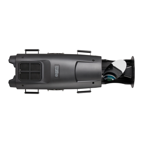
Page 12: Fixture Overview
Adjustable yoke (see Yoke Assembly on the facing page for details) Fans and dust filter powerCON TRUE TOP power input and thru connectors Display and navigation controls USB port Ethernet ports (x2) DMX In and DMX Thru connectors Cyberlight LED User Manual... -
Page 13: Yoke Assembly
Yoke Assembly Item Description Quantity Yoke Yoke locking knob 8 mm (5/16 in) flat washer 8 mm (5/16 in) carriage bolt Yoke pivot screw (M10x35 mm) 2 Washer Degree label Specifications For complete technical specifications, see the technical datasheet: etcconnect.com/Products/High-End-Systems/Lighting-Fixtures/Cyberlight/Documentation.aspx Environment Ambient operating temperature range: -10°C to 40°C (14°F to 104°F). •... -
Page 14: Power
Fixtures per Circuit One fixture can be linked via the power thru connector (2 fixtures total per circuit). The fixtures per circuit information assumes the use of an ETC R20 breaker module. Consult the upstream breaker trip curves when using other equipment. -
Page 15: Fixture Installation Hardware
Fixture Installation Hardware The top of the yoke has two 13 mm (1/2 in) diameter mounting holes for attaching installation hardware. Installation hardware is not provided with the Cyberlight LED fixture. Select appropriately sized hardware for your installation. The installation hardware you choose must be capable of supporting, at a minimum, the weight of the fixture (38 kg [84 lb]) and the associated cables. - Page 16 4. Rotate the yoke to the desired position. Use the markings on the degree label for precise positioning. 5. Firmly tighten the yoke locking knobs to secure the yoke in place. 6. Firmly tighten the yoke pivot screws. Cyberlight LED User Manual...
-
Page 17: Install The Fixture
Install the Fixture Overhead rigging must be performed by qualified personnel. Follow all local and national codes and recommended practices. WARNING: The installation location must support a minimum point load of 6 times • the weight of the fixture. The installation must always be secured with a secondary safety •... - Page 18 You can install the fixture in any of the orientations shown below. ETC recommends that you use three people to install each Cyberlight LED fixture: two people to hold the fixture while the third person secures the fixture to the installation location.
-
Page 19: Dmx Control
DMX Control The Cyberlight LED fixture operates on standard DMX-512 control bus, controlled by a DMX console. The fixture requires 40 channels of DMX-512. Attach the fixture to the control bus using a two-core, shielded cable with a 5-pin XLR connector (Belden 9729 is preferred). -
Page 20: Terminate Dmx
1, you could set the second fixture to 41 (40+1), the third to 81 (40+41), and so on. DMX Channels The current DMX channel map for the Cyberlight LED can be found on the ETC website: etcconnect.com/Products/High-End-Systems/Lighting-Fixtures/Cyberlight/Documentation.aspx Cyberlight LED User Manual... -
Page 21: Ethernet Control
Ethernet Control The Cyberlight LED fixture includes two Ethernet ports that allow sending and receiving of control signals using the Art-Net protocol or sACN. Use a Cat5e (or better) cable and terminate to RJ45 connectors following the TIA/EIA 568B wiring standard. -
Page 22: Ethernet Control And Dmx Thru
DMX Address on page 19 Example: The Cyberlight LED requires 40 channels of control. If you set the DMX starting address of the first fixture to 1, you could set the second fixture to 41 (40+1), the third to 81 (40+41), and so on. -
Page 23: Configure The Fixture
Configure the Fixture You can configure the Cyberlight LED fixture through the onboard user interface. Connect the fixture to power before you configure it. If you do not provide power, the fixture will use battery power to power the user interface. -
Page 24: Dmx Address
Settings Menu Navigate: Main Menu → Settings The Settings menu provides access to configure and set up the Cyberlight LED. Provide power to the fixture before configuring it. If you do not provide power, the fixture will use battery power to power the user interface. -
Page 25: Set The Network Options
Set the Network Options Note: The Network menu is hidden when the Control Protocol setting is DMX. Navigate: Main Menu → Settings → Network Parameter Value Description When sACN is the selected Sets the universe. Protocol, set a value of 1-256. Universe The default setting for sACN is 1. -
Page 26: Set The Pan/Tilt Options
Set the Fan Options Navigate: Main Menu → Settings → Fan Select the fan mode for the fixture. The default setting is Auto. Auto • Studio - reduces fan noise, but decreases fixture output by ~20% • Cyberlight LED User Manual... -
Page 27: Set The Display Options
Navigate: Main Menu → Settings → Software Update → USB Update Software updates for the Cyberlight LED fixture are available on the ETC website at etcconnect.com/Products/High-End-Systems. 1. Download the firmware zip file from the ETC website. -
Page 28: Calibration Options
Each fixture restarts when the update is complete, and the display returns to its default • state. 5. When all of the Cyberlight LED fixtures on the data run have been updated to the new firmware version, reconnect the DMX control source to the host fixture's DMX IN port. Calibration Options Navigate: Main Menu →... -
Page 29: Test Options
Test Options Navigate: Main Menu → Home/Test → Test Run a self-test program on features and attributes of the Cyberlight LED fixture. When you run the test, the display indicates "Running" and the fixture automatically runs a self-test procedure, testing each of the functions. Press [MODE/ESC] button to end the self-test and return the display to the previous menu. -
Page 30: View Sensors
RDM Device Label - a compatible RDM controller can read and write the device label • RDM Device ID - a unique device ID • IP Address - an Ethernet IP address assigned in the Settings → Network → Set IP Address • menu. Cyberlight LED User Manual... -
Page 31: Change The Offset Of The Mirror Head
Change the Offset of the Mirror Head You can offset the mirror head up to 20 degrees left or right of center for a total range of 40 degrees. Tool required: 5.0 mm hex key • 1. Loosen (but do not remove) the thumb screw and four hex screws located at the base of the mirror head. -
Page 32: Replace A Gobo
If you are installing a custom gobo, a metal gobo mounting ring with alignment tab is available from ETC to help with the alignment of gobos between fixtures. Contact ETC or your authorized ETC dealer to order part number H7900110 for standard gobos and 2570A3022 for gobos in which the image covers the full diameter of the gobo, such as the Ice gobo. - Page 33 2. Remove the fixture cover from the front of the fixture. a. Using a #2 Philips screwdriver, loosen the four captured Phillips screws that secure the cover to the fixture. b. Lift the cover away from the fixture, and detach the safety tether from the fixture enclosure to completely remove the cover.
-
Page 34: Replace A Gobo
The illustrations used in this procedure display gobo wheel 1. The procedure for replacing a gobo in gobo wheel 2 is the same with one exception; ETC recommends that you set the effects module on the work surface with the gobo wheels down for easier access to the gobos in gobo wheel 2. - Page 35 4. Remove the gobo from the gobo carrier. a. Use a flatblade jeweler's screwdriver to carefully pry the spring out of the gobo carrier. b. Remove the gobo media from the gobo carrier. 5. Identify the reflective side of the new gobo. The reflective side must be oriented in the gobo carrier so that when the effects module is installed in the fixture, the reflective side is toward the LED engine.
- Page 36 Rotate the sun gear of the gobo wheel until the magnet on each gobo carrier in the gobo wheel is aligned with its corresponding alignment key on the sun gear. Note: If you are unable to align all of the gobos appropriately as shown below, contact ETC Technical Services for assistance. Item Description Sun gear...
- Page 37 9. For the new gobo you are installing, rotate the sun gear on the gobo carrier so that the magnet is centered between the forks of the gobo carrier. 10. Slide the gobo carrier partially into the gobo wheel making sure the forks on the gobo carrier fit on either side of the post beneath the rotating sun gear on the gobo wheel.
-
Page 38: Install The Effects Module
4. Reinstall the fixture cover. a. Align the cover to the fixture and reattach the safety tether to the fixture enclosure. b. Using a #2 Phillips screwdriver, tighten the four captured Phillips screws to secure the cover to the fixture. Cyberlight LED User Manual... -
Page 39: Replace Color Media
Remove the Color Module Tip: If you position the fixture on its side when removing the color module, ETC recommends that you tilt the yoke toward the head of the fixture to increase the stability of the fixture. -
Page 40: Replace Color Media
2. Gently press up on the underside of the color media you want to remove to lift the media away from the color wheel, and pull the media out of the color wheel. 3. Insert the replacement color media into the color wheel making sure to fully seat the media in the color wheel. Cyberlight LED User Manual... -
Page 41: Install The Color Module
Install the Color Module Tool required: #2 Philips screwdriver • 1. Carefully slide the color module into the fixture. 2. Using a #2 Philips screwdriver and the two screws you set aside when you removed the color module, secure the color module to the fixture. 3. -
Page 42: Install The Snoot Accessory
Install the Snoot Accessory A snoot accessory for the Cyberlight LED fixture is available separately for purchase. Contact ETC Technical Services or your authorized ETC dealer for information. See Help from Technical Services on page 2 for contact information. The snoot accessory kit contains the snoot and three M3x4 mm hex screws. -
Page 43: Error Codes
UI display and details about the errors are listed in Main Menu → Diagnostics → Errors. Help from Technical Contact ETC Technical Services for assistance in remedying the errors. See Services on page 2 for contact information. - Page 44 Check the sensor PCB wiring and verify that wires are not broken or • sensor for rotating gobo wheel 2. Sensor unplugged from the sensor or motor driver board. Confirm that rotating gobo wheel 2 is not obstructed and is able to move • freely. Cyberlight LED User Manual...
-
Page 45: Maintenance
Clean Fans and Dust Filters The Cyberlight LED fixture contains eight fans: four on each side of the fixture. The fans are located behind the fan doors near the rear of the fixture. Clean the fans and dust filters regularly to ensure maximum airflow and efficient cooling. -
Page 46: Clean The Mirror
Optical Cloth with purified water or an ammonia-free glass cleaner such as Miller Stevenson MS-260 Glass Cleaner. Replace the Fuse The fuse in this fixture is not user-replaceable. Contact ETC Technical Services for assistance. Help from Technical Services on page 2 for contact information. -
Page 47: Compliance
For current and complete compliance information, view the product datasheet at etcconnect.com/Products/High-End-Systems. For complete product documentation, including compliance documentation, visit etcconnect.com/products. FCC Compliance Cyberlight LED (For any FCC matters): Electronic Theatre Controls, Inc. 3031 Pleasant View Road Middleton, WI 53562 +1 (608) 831-4116 etcconnect.com... - Page 48 | Support support.etcconnect.com | Contact etcconnect.com/contactETC © 2022 Electronic Theatre Controls, Inc. | Trademark and patent info: etcconnect.com/ip Product information and specifications subject to change. ETC intends this document to be provided in its entirety. 2597M1200-1.0.0 Rev D Released 2022-04...
Need help?
Do you have a question about the Cyberlight LED and is the answer not in the manual?
Questions and answers