
Related Manuals for Epever Tracer6210AN


Summary of Contents for Epever Tracer6210AN
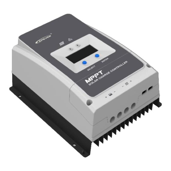
- Page 1 MPPT Solar Charge Controller User Manual Model: Tracer6210AN Tracer5415AN/Tracer6415AN Tracer8415AN/Tracer10415AN Tracer5420AN/Tracer6420AN Tracer8420AN/Tracer10420AN...
-
Page 3: Table Of Contents
Contents Important Safety Instructions 1 General Information 1.1 Overview 1.2 Characteristics 1.3 Naming rules 2 Installation 2.1 Attentions 2.2 Requirements for the PV array 2.3 Wire size 2.4 Dry contact instruction 2.5 Mounting 3 Operation 3.1 Indicator 3.2 Buttons 3.3 LCD Display 3.4 Setting 4 Others 4.1 Protections... -
Page 5: Important Safety Instructions
Important Safety Instructions Please reserve this manual for future review. This manual contains all safety, installation, and operation instructions for the Tracer-AN series MPPT solar controller ("controller" referred to in this manual). Read all the instructions and warnings carefully in the manual before installation. ... -
Page 6: General Information
1 General Information 1.1 Overview The Tracer-AN controllers, based on the multiphase synchronous rectification technology(MSRT) and advanced MPPT control algorithm, adopt a dual-core processor and co-negative design. This help features the controllers with fast response characteristics, high reliability, and industrial standards. MSRT guarantees a high conversion efficiency in any charging power, which sharply improves the solar system's energy efficiency. -
Page 7: Characteristics
Up to 6 controllers connection in parallel to expand the system Load dry contact to control the external load switch To set the first and the second disconnection voltage of load by the software Auto-control of utility and generator dry contact design to compose a hybrid power system easily ... -
Page 8: Naming Rules
❼ (Generator/Load) dry contact enable ⓰ ENTER button ⑴ switch ❽ RTS interface ⓱ LCD ❾ RS485 port(5VDC/200mA) ⓲ Fault indicator (1) Set the (Generator/Load) dry contact enable switch to ON, the (Load) dry contact is enabled; while it is disabled when the switch is set to OFF. (2) Connect an RTS (Remote Temperature Sensor) to detect the battery temperature remotely. -
Page 9: Installation
According to the open-circuit voltage (VOC) and the maximum power point voltage (VMPP) of the MPPT controller, the serial connection of PV modules suitable for different controllers can be calculated. The below table is for reference only. Tracer6210AN: 36cell 48cell 54cell 60cell Voc<... - Page 10 The above parameters are calculated under standard test conditions (STC (Standard Test Condition): Module Temperature 25℃, Air Mass1.5, Irradiance IMPORTANT 1000W/m Tracer5415/6415/8415/10415AN: 36cell 48cell 54cell 60cell Voc< 23V Voc< 31V Voc< 34V Voc< 38V System voltage Max. Best Max. Best Max.
-
Page 11: Wire Size
The PV array's ISC must not exceed the controller's maximum PV input current. For max. PV input current and max. PV wire size, please refer to the table below: Model Max. PV input current Max. PV wire size Tracer5415AN 16mm /6AWG Tracer5420AN Tracer6210AN Tracer6415AN 16mm /6AWG Tracer6420AN Tracer8415AN 25mm /4AWG Tracer8420AN... -
Page 12: Dry Contact Instruction
The wire size is only for reference. Suppose a long distance exists between the PV array and the controller or between the controller and the battery. In that case, larger wires shall be used to reduce the voltage drop and improve the system performance. -
Page 13: Mounting
The Battery Control Voltage Parameters refer to chapter Setting. CAUTION The (Utility/Generator) dry contact OFF interface is closed when the system is powered off. Please check the system in time. WARNING Refer to below the diagram: 2.5 Mounting Risk of explosion! Never install the controller in a sealed enclose with flooded batteries! Do not install the controller in a confined area where battery gas can accumulate. - Page 14 Ventilation is highly recommended if mounted in an enclosure. CAUTION Step2: Remove the terminal protective cover. Step 3: Connect the battery (Left) and PV (Right) Disconnect the system in reverse order. IMPORTANT Tracer-AN series controllers have no battery reverse protection. Do not reverse the battery during the wiring.
- Page 15 controller's (Load) dry contact to the inverter's start-stop dry contact. Otherwise, the controller may be damaged Single controller Connection in parallel...
- Page 16 Step 4:Grounding Tracer-AN series are common-negative controllers. Negative terminals of the PV array, the battery can be grounded simultaneously, or any terminal is grounded. However, according to the practical application, the PV array's negative terminals, battery, and load can also be ungrounded. Simultaneously, the grounding terminal on the shell must be grounded, which effectively shields the electromagnetic interference from the outside and prevents some electric shock to the human body.
-
Page 17: Operation
3 Operation Note: The display screen can be viewed clearly when the angle between the end-users horizontal sight and the display screen is within 90° . If the angle exceeds 90° , the information on the display screen cannot be viewed clearly. 3.1 Indicator Indicator Color... -
Page 18: Lcd Display
3.3 LCD Display 1) Status Description Name Symbol Status Night PV array No charge Charging PV array's voltage, current, and generate energy Battery capacity, In Charging Battery Battery Voltage, Current, Temperature Battery type (Load) dry contact connected Load (Load) dry contact disconnected 2)... -
Page 19: Setting
3) Error codes Faults Charging Status Symbol Instruction Indicator indicator Battery level shows empty, Battery over Red ON battery frame blink, fault icon discharged solid blink. Battery over Red Slow Battery level shows full, battery voltage flashing frame blink, fault icon blink. Battery level shows current Battery over... - Page 20 ② Set the battery type via the LCD ④ User(Apply to "MT50" and "PC ①Sealed (Default) ②Gel ③Flooded software "Solar Station Monitor") Operation: On the battery voltage interface, long-press the "ENTER" button until the battery type interface flashes. Then press the "SELECT" button to change the battery type, and press the "ENTER" button to confirm. The controller can only set the lead-acid battery type.
- Page 21 The controller can only set the lead-acid battery type. The lithium battery type must be set through the PC or APP. CAUTION ④ Battery voltage control parameters Lead-acid battery parameters The parameters are measured in the condition of 12V/25 º C. Please double the values in the 24V system and quadruple the values in the 48V system.
- Page 22 E. Boost Reconnect Charging voltage >Low Voltage Reconnect Voltage. Lithium battery parameters The parameters are measured in the condition of 12V/25 º C. Please double the values in the 24V system and quadruple the values in the 48V system. Battery type Li(NiCoMn)O2 User...
-
Page 23: Others
4 Others 4.1 Protections Tracer AN series controllers have no battery reverse protection. Do not reverse the battery during the wiring. Otherwise, the controller may be damaged. WARNING Protections Instruction When the PV array's actual charging current or power exceeds the current/power-limiting controller's rated charging current or power, the controller charges the protection... -
Page 24: Troubleshooting
temperature protection lower than the Low Temperature Protection Threshold (LTPT), the controller stops charging and discharging automatically. When the detected temperature exceeds the LTPT, the controller resumes work automatically. (The LTPT is 0 ° C by default and can be set within 10 ~ -40 °... -
Page 25: Maintenance
Please check the battery's voltage The wire connection is correct; the The battery voltage (at least 8V voltage to activate the controller is not working. is lower than 8V. controller). Check whether the battery voltage is higher than OVD (over voltage Battery over voltage disconnect voltage) and disconnect the PV array connection. -
Page 26: Specifications
5 Specifications Model Tracer5415AN Tracer5420AN Electrical Parameters System rated voltage 12/24/36/48VDC or Auto Controller working voltage 8V ~ 68V range Lead-acid battery type Sealed(Default) / Gel / Flooded / User Lithium battery type LiFePO4 / Li(NiCoMn)O2 / User Battery fuse 80A / 58V Rated charging current Rated charging power... - Page 27 Model Tracer6210AN Electrical Parameters System rated voltage 12/24VDC or Auto Controller working voltage 8V ~ 32V range Lead-acid battery type Sealed(default) / GEL / FLD / user-defined. Lithium battery type LiFePO4 / Li(NiCoMn)O2 / User Battery fuse 80A/58V Rated charging current...
- Page 28 Lead-acid battery type Sealed(default) / GEL / FLD / user-defined. Lithium battery type LiFePO4 / Li(NiCoMn)O2 / User Battery fuse 80A/58V Rated charging current Rated charging power 750W/12V, 1500W/24V, 2250W/36V, 3000W/48V 150V(at the lowest 200V(at the lowest temperature) Max. PV open-circuit voltage temperature) 180V(at 25℃) 138V(at 25℃)
- Page 29 Rated charging power 1000W/12V, 2000W/24V, 3000W/36V, 4000W/48V 150V(at the lowest temperature) 200V(at the lowest temperature) Max. PV open-circuit voltage 138V(at 25℃) 180V(at 25℃) (Battery voltage +2V) (Battery voltage +2V) MPPT voltage range ~ 108V(at 25℃) ~ 144V(at 25℃) ≥99.5% MPPT tracking efficiency Max.
- Page 30 ~ 108V(at 25℃) ~ 144V(at 25℃) ≥99.5% MPPT tracking efficiency Max. conversion efficiency 98.6% 98.5% Full load efficiency 98.0% 97.6% Temperature compensate -3mV/℃/2V(Default) coefficient Self-consumption 98mA/12V, 60mA/24V, 50mA/36V, 46mA/48V Grounding type Common negative grounding Dry contact Rated value: 5A/30VDC, Max. value: 0.5A/60VDC ①...
-
Page 31: Appendix 1 Dimensions
Appendix 1 Dimensions (Unit: mm) Tracer5415/5420AN... - Page 32 Tracer6210AN...
- Page 33 Tracer6415/6420AN...
- Page 34 Tracer8415/8420AN...
- Page 35 Tracer10415/10420AN Any changes without prior notice! Version number: V3.4...
- Page 36 HUIZHOU EPEVER TECHNOLOGY CO., LTD. Tel: +86-752-3889706 E-mail: info@epever.com Website: www.epever.com...
Need help?
Do you have a question about the Tracer6210AN and is the answer not in the manual?
Questions and answers