
Related Manuals for Epever Tracer-AN Series


Summary of Contents for Epever Tracer-AN Series
- Page 1 Tracer-AN series MPPT Solar Charge Controller —— User Manual Model: Tracer5415AN/Tracer6415AN Tracer8415AN/Tracer10415AN Tracer5420AN/Tracer6420AN Tracer8420AN/Tracer10420AN...
- Page 3 Important Safety Instructions Please reserve this manual for future review. This manual contains all instructions of safety, installation and operation of Tracer-AN series ("the controller" is referred in this manual). General Safety Information Read carefully all the instructions and warnings in the manual before installation.
-
Page 4: Table Of Contents
Contents 1 General Information ....................1 1.1 Overview .....................1 1.2 Characteristics ..................2 1.3 Accessories (Included) ................3 1.4 Designations of Controller Models ............3 2 Installation ........................ 4 2.1 General Installation Notes ..............4 2.2 PV Array Requirements ...............4 2.3 Wire Size .....................8 2.4 Mounting .....................9 3 Operation ....................... -
Page 5: General Information
PV modules and operate under high temperature environment. With the adaptive three-stage charging mode based on digital control circuit, Tracer-AN series controllers can effectively prolong the life-cycle of battery and significantly improve the system performance. -
Page 6: Characteristics
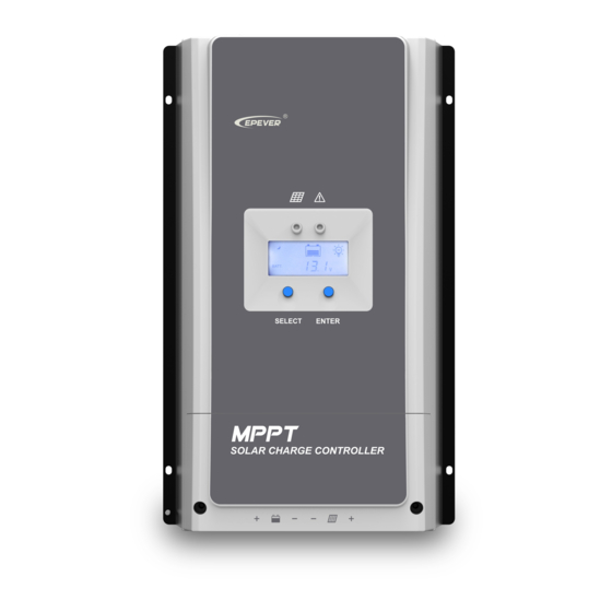
Isolated RS-485 with 5VDC/200Ma protected output for no power devices, with MODBUS protocol Monitor and set the parameters via mobile phone APP or PC software 1.2 Characteristics Figure 1 Characteristics ❶- ❿- Charging LED indicator Utility/Diesel generator relay ON ❷- ➀- SELECT button... -
Page 7: Accessories (Included)
(3) Connect for a RTS (Remote Temperature Sensor) to remotely detect battery temperature. If the temperature sensor is short-circuited or damaged, the controller will charge or discharge at the default temperature setting of 25 º C. (4) Common negative design, with the same terminal of the PV and battery. 1.3 Accessories (Included) Item Accessory... -
Page 8: Installation
2 Installation 2.1 General Installation Notes Before installation, please read through the entire installation instructions to get familiar with the installation steps. Be very careful when installing the batteries, especially flooded lead-acid battery. Please wear eye protection, and have fresh water available to wash and clean any contact with battery acid. - Page 9 72cell Voc<46V 96cell Voc<62V Thin-Film Module System voltage Voc>80V MAX. Best MAX. Best NOTE: The above parameter values are calculated under standard test conditions (STC ,Module Temperature 25℃,Air Mass1.5.) (Standard Test Condition):Irradiance 1000W/m Tracer5420/6420/8420/10420AN: 36cell 48cell 54cell 60cell System Voc<23V Voc<31V Voc<34V Voc<38V...
- Page 10 Condition 3: Actual charging power of PV array>Rated charging power of controller Condition 4: Actual charging current of PV array>Rated charging current of controller When the controller operates under “Condition 3”or“Condition 4”, it will carry out the charging as per the rated current or power. WARNING: When the power of PV module is greater than the rated charging power, and the maximum open-circuit voltage of PV array is more than 150V(Tracer**15AN)/200V(Tracer**20N) (at the lowest environmental temperature)
- Page 11 Rated Charge Rated Charge Item Max. PV Power Max. PV Open Circuit Current Power 625W/12V 937.5W/12V 1250W/24V 1875W/24V Tracer5415AN 1875W/36V 2812.5W/36V 2500W/48V 3750W/48V 750W/12V 1125W/12V 1500W/24V 2250W/24V Tracer6415AN 2250W/36V 3375W/36V 150V (At Min. operating environment Tem.) 3000W/48V 4500W/48V 138V 1000W/12V 1500W/12V 2000W/24V 3000W/24V...
-
Page 12: Wire Size
2.3 Wire Size The wiring and installation methods must conform to all national and local electrical code requirements. PV Wire Size Since PV array output can vary due to the PV module size, connection method or sunlight * angle, the minimum wire size can be calculated by the Isc of PV array. -
Page 13: Mounting
2.4 Mounting WARNING: The controller doesn’t have battery reverse polarity protection. DO NOT reversely connect the battery wires, the controller may be damaged. WARNING: Risk of explosion! Never install the controller in a sealed enclose with flooded batteries! Do not install in a confined area where battery gas can accumulate. - Page 14 Step 2:Remove the terminal protective cover Step3:Connect the battery and PV NOTE: Disconnect the system in the reverse order...
- Page 15 WARNING:The controller doesn’t have battery reverse polarity protection. DO NOT reversely connect the battery wires, the controller may be damaged. CAUTION: While wiring the controller do not close the circuit breaker or fuse and make sure that the leads of "+" and "-" poles are connected correctly. CAUTION: A fuse which current is 1.25 to 2 times the rated current of the controller must be installed on the battery side with a distance from the battery not greater than 150 mm.
- Page 16 Connect the accessories for RS485 communication, refer to the accessories list. Step 7:Powered on the controller Turn on the battery fuse to power on the controller, then check the LCD is OFF or the fault indictor is ON when the controller is normal. CAUTION: If the controller is not operating properly or the battery indicator on the controller shows an abnormality, please refer to 4.2 “Troubleshooting”.
-
Page 17: Operation
3 Operation 3.1 Indicator Color Status Instruction Indicator PV connection normal but low Green On Solid voltage(irradiance) from PV, no charging No PV voltage(night time) or Green Charging PV connection problem LED indicator Green Slowly Flashing In charging Green Fast Flashing PV over voltage 3.2 Button Button... - Page 18 PV array Night No charging Charging PV Voltage, Current, Power Battery capacity, In Charging Battery Battery Voltage, Current, Temperature Battery Type Load control delay turn ON Load control delay turn OFF Load Load control delay control the load voltage, current, energy and work mode ...
-
Page 19: Setting
Battery level shows current Battery over —— value, battery frame blink, slowly temperature fault icon blink. flashing Green Battery level shows current Controller over value, battery frame blink, slowly slowly temperature fault icon blink. flashing flashing Battery level shows current Green System voltage value, battery frame blink,... - Page 20 Battery charging setting Sealed Flooded User Boost Charging Voltage 14.4V 14.2V 14.6V 9~17V Float Charging Voltage 13.8V 13.8V 13.8V 9~17V Boost Reconnect Charging 13.2V 13.2V 13.2V 9~17V Voltage Low Voltage Reconnect Voltage 12.6V 12.6V 12.6V 9~17V Under Voltage Warning 12.2V 12.2V 12.2V 9~17V...
-
Page 21: Protections, Troubleshooting & Maintenance
4 Protections, Troubleshooting & Maintenance 4.1 Protections When the charging current or power of the PV array exceeds the controller’s rated current or power, it will be charge PV Over at the rated current or power. Current/power NOTE: When the PV modules are in series, ensure that the open-circuit voltage of the PV array does not exceed the "maximum PV open-circuit voltage"... -
Page 22: Troubleshooting
4.2 Troubleshooting Faults Possible reasons Troubleshooting The LED&LCD is off during daytime when Confirm that PV and battery wire PV array disconnection sunshine falls on PV connections are correct and tight modules properly Please check the voltage of Battery voltage is lower Wire connection is battery. - Page 23 Confirm that all the terminals have no corrosion, insulation damaged, high temperature or burnt/discolored sign, tighten terminal screws to the suggested torque. Check for dirt, nesting insects and corrosion. If so, clear up in time. Check and confirm that lightning arrester is in good condition. Replace a new one in time to avoid damaging of the controller and even other equipments.
-
Page 24: Specifications
5 Specifications Electrical Parameters Item Tracer5415AN Tracer6415AN Tracer8415AN Tracer10415AN Tracer5420AN Tracer6420AN Tracer8420AN Tracer10420AN Nominal System 12/24/36/48VDC or Auto Voltage Battery Input 8V~68V Voltage Range Battery Type Sealed/Gel/Flooded/User Rated charge 100A 100A current 625W/12V 750W/12V 1000W/12V 1250W/12V 625W/12V 750W/12V 1000W/12V 1250W/12V Rated charge 1250W/24V 1500W/24V... - Page 25 Environmental Parameters Ambient temperature range -25℃~+45℃ LCD temperature range -20℃~+70℃ Storage temperature range -30℃~+85℃ ≤95%, N.C. Humidity Enclosure IP20 Mechanical Parameters Item Tracer5415/5420AN Tracer6415/6420AN Dimension 261×216×119mm 340×236×119mm Mounting dimension 180×204mm 260×224mm Φ7 Mounting hole size Terminal 6AWG(16mm 2AWG(35mm Recommended cable 6AWG(16mm 16mm /5AWG...
-
Page 26: Annex I Dimensions
Annex I Dimensions Tracer5415/5420AN Dimensions(Unit:mm) - Page 27 Tracer6415/6420AN Dimensions(Unit:mm)
- Page 28 Tracer8415/8420AN Dimensions(Unit:mm)
- Page 29 Tracer10415/10420AN Dimensions(Unit:mm) Any changes without prior notice! Version number:V1.00...
- Page 32 BEIJING EPSOLAR TECHNOLOGY CO., LTD. Tel: +86-10-82894112 / 82894962 Fax: +86-10-82894882 E-mail:info@epsolarpv.com Website: http://www.epsolarpv.com/ http://www.epever.com/...
Need help?
Do you have a question about the Tracer-AN Series and is the answer not in the manual?
Questions and answers
Does it recognize input voltage automatically
Yes, the Epever Series automatically identifies the system voltage (12/24VDC).
This answer is automatically generated