
Subscribe to Our Youtube Channel
Related Manuals for Epever MPPT Tracer1206AN


Summary of Contents for Epever MPPT Tracer1206AN
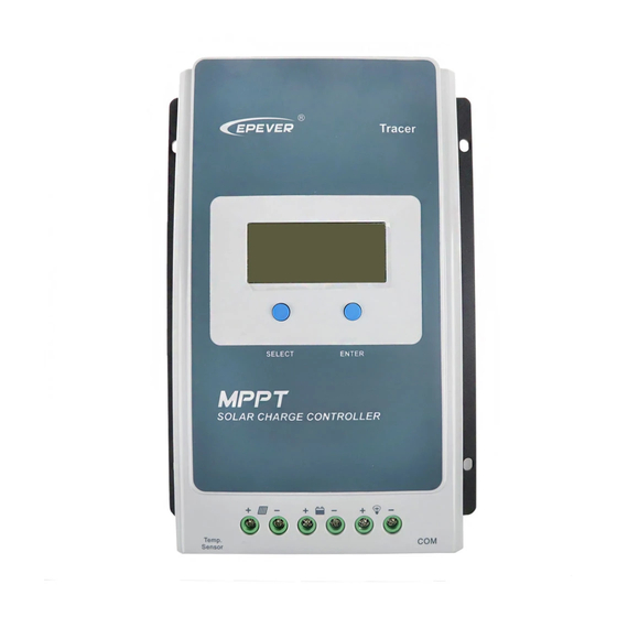
- Page 1 MPPT Solar controller User Manual Model Tracer1206AN/Tracer2206AN Tracer1210AN/Tracer2210AN Tracer3210AN/Tracer4210AN...
- Page 3 Important Safety Instructions Please reserve this manual for future review. This manual contains safety, installation, and operation instructions for the Tracer-AN series MPPT solar controller ("controller" referred to in this manual). Read all the instructions and warnings carefully in the manual before installation. ...
-
Page 4: Table Of Contents
Contents 1 General Information ................ 1 1.1 Overview ......................1 1.2 Characteristics ....................2 1.3 Naming rules ....................3 1.4 Maximum Power Point Tracking Technology........... 3 1.5 Battery charging stage ..................4 2 Installation ..................7 2.1 Attentions ....................... 7 2.2 Requirements for the PV array ................ -
Page 5: General Information
1 General Information 1.1 Overview Adopting the advanced MPPT control algorithm, Tracer-AN solar controller can minimize the maximum power point loss rate and loss time. It makes this product tracks the PV array's maximum power point and obtains maximum energy under any situation. Compared with the PWM charging method, MPPT solar controllers can increase the energy utilization ratio by 10%-30%. -
Page 6: Characteristics
Standard Modbus communication protocol based on the RS485 communication bus, making the communication distance longer A power protection chip, which can provide 5VDC/200mA power and over-current, short-circuit protections, is adopted by the communication interface Support monitoring and setting the parameters via the APP or PC software ... -
Page 7: Naming Rules
1.3 Naming rules Common Negative System Max. PV open circuit voltage 100V System Voltage12/24VDC Charge & discharge current10A Product Series 1.4 Maximum Power Point Tracking Technology Due to the nonlinear characteristics of the solar array, there is a maximum energy output point (Max Power Point) on its curve. -
Page 8: Battery Charging Stage
According to the test, the MPPT controller can raise 20%-30% efficiency compared to the PWM controller. (Specified value may be fluctuant due to the influence of the circumstance and energy loss.) Figure 1-2 Maximum Power Point Tracking Technology In actual application, as shading from cloud, tree, and snow, the panel may appear Multi-MPP. However, in actuality, there is only one real Maximum Power Point. - Page 9 Figure 1-4 Battery charging stage curve A) Bulk Charging The battery voltage has not yet reached constant voltage (Equalize or Boost Charging Voltage). The controller operates in constant current mode, delivering its maximum current to the batteries (MPPT Charging). When the battery voltage reaches the constant voltage set point, the controller will start to operate in constant charging mode.
- Page 10 Equipment damage! Equalization may increase battery voltage to the level that damages sensitive DC loads. Verify that the load's allowable input voltages are greater than the equalizing charging setpoint voltage. Over-charging and excessive gas precipitation may damage the battery plates CAUTION and activate material shedding on them.
-
Page 11: Installation
2 Installation 2.1 Attentions Be careful when installing the batteries. Please wear eye protection when installing the open-type lead-acid battery and rinse with clean water in time for battery acid contact. Keep the battery away from any metal objects, which may cause a short circuit of the battery. ... - Page 12 The above parameters are calculated under the STC (Standard Test Condition)--module temperature 25℃, air mass1.5, irradiance 1000W/m2.) CAUTION Tracer1210/2210/3210/4210AN: 36cell 48cell 54cell 60cell Voc< 23V Voc< 31V Voc< 34V Voc< 38V System voltage Max. Best Max. Best Max. Best Max. Best 72cell Voc<...
-
Page 13: Wire Size
Condition 4: Actual charging current of the PV array>Rated charging current of the controller When the controller operates under "Condition 3" or "Condition 4," ,it will carry out the charging as per the rated current or power. The controller may be damaged when: 1. - Page 14 PV wire size The PV array's output current varies with its size, connection method, and sunlight angle. The minimum wire size can be calculated by its ISC (short circuit current). Please refer to the ISC value in the PV module's specifications.
-
Page 15: Mounting
performance. The recommended wire is selected for the battery according to the conditions that its terminals are not connected to any additional inverter. 2.4 Mounting Risk of explosion! Never install the controller in a sealed enclose with flooded batteries! Do not install the controller in a confined area where battery gas can accumulate. - Page 16 Figure 2-2 Wiring Diagram Please do not close the circuit breaker or fuse during the wiring and ensure that the leads of "+" and "-" poles are polarity correctly. A fuse whose current is 1.25 to 2 times the controller's rated current must be installed on the battery side with a distance from the battery no longer than CAUTION 150 mm.
- Page 17 Optional Accessory: Included Accessory: Remote Temperature Sensor External temperature sensor (Model: RT-MF58R47K3.81A) (Model: RTS300R47K3.81A) Connect one end of the remote temperature sensor cable to the interface ③ and place the other end close to the battery. Suppose the remote temperature sensor is not connected to the controller or damaged.
-
Page 18: Operation
3 Operation 3.1 Buttons Mode Note Load ON/OFF It can turn the load On/Off via the ENTER button in manual load mode. Clear fault Press the ENTER button. Browsing mode Press the SELECT button. Press the ENTER button and hold on 5s to enter the setting mode. Press the SELECT button to set the parameters. - Page 19 Battery Voltage, Current, Temperature Battery type Load ON Load Load OFF Current/Consumed energy/Load mode 2) Error codes Status Icon Instruction Battery Battery level shows empty, battery frame over-discharged blink, fault icon blink Battery level shows full, battery frame Battery over voltage blink, fault icon blink Battery level shows current value, battery Battery overheating...
-
Page 20: Setting
3.3 Setting Clear the generated energy Step 1: Press the ENTER button and hold 5s under the PV-generated energy interface, and the value will be flashing. Step 2: Press the ENTER button to clear the generated energy. Switch the battery temperature unit Press the button and hold 5s under the battery temperature interface. - Page 21 Step4: Press the ENTER button to confirm. ③ Set the battery parameters under "USE" battery type Setting the battery parameters by PC software Connect the controller's RJ45 interface to the PC's USB interface via a USB to RS485 cable (model: CC-USB-RS485-150U).
- Page 22 1) Press the ENTER button again to display the 14.4V 9~17V current voltage value. 2) Press the SELECT button to modify the parameter 13.8V 9~17V (short press to increase 0.1V, long press to 12.6V 9~17V decrease 0.1V). 3) Press the ENTER button to confirm and enter the 9~17V 11.1V next parameter.
- Page 23 system. Battery type Battery Sealed User parameters Over voltage disconnect 16.0V 16.0V 16.0V 9~17V voltage Charging limit voltage 15.0V 15.0V 15.0V 9~17V Over voltage reconnect 15.0V 15.0V 15.0V 9~17V voltage Equalize charging voltage 14.6V 14.8V 9~17V Boost charging voltage 14.4V 14.2V 14.6V 9~17V...
- Page 24 Battery type LNCM LCNM LCNM LCNM LFP4S LFP8S User Battery parameters Over voltage 14.8V 29.6 V 12.8 V 25.6 V 29.8 V 9~17V disconnect voltage Charging limit voltage 14.6 V 29.2 V 12.6 V 25.2 V 29.4 V 9~17V Over voltage 14.6 V 29.2 V...
- Page 25 C. Low Voltage Reconnect Voltage > Low Voltage Disconnect Voltage ≥ Discharging Limit Voltage. D. Under Voltage Warning Reconnect Voltage>Under Voltage Warning Voltage≥ Discharging Limit Voltage; E. Boost Reconnect Charging voltage> Low Voltage Reconnect Voltage; F. Low Voltage Disconnect Voltage ≥ Over Discharging Protection Voltage (BMS)+0.2V The required accuracy of BMS is no higher than 0.2V.
- Page 26 Please set Light ON/OFF, Test mode, and Manual mode via Timer1. Timer2 will be disabled and display "2 n ". CAUTION ② Load mode setting Load mode setting by PC software Connect the controller's RJ45 interface to the PC's USB interface via a USB to RS485 cable (model: CC-USB-RS485-150U).
-
Page 27: Others
4 Others 4.1 Protections Protections Instruction When the actual PV array's charging current or power is higher than the PV Over Current controller's rated charging current or power, the controller will charge the battery per the rated current or power. When not in the PV charging state, the controller will not be damaged in the case of short-circuiting in the PV array. -
Page 28: Troubleshooting
automatically (The LTPT is 0 ° C by default and can be set within the range of 10 ~ -40 ° C). When a short circuit occurs on the load side (which is 4 times higher than the rated load current), the controller automatically cuts off the output. The output still attempts to resume five times automatically (delay 5 seconds, 10 Load short seconds, 15 seconds, 20 seconds, 25 seconds). - Page 29 Check whether the battery voltage is Battery over higher than OVD (over voltage Battery frame blink, voltage disconnect voltage) and disconnect the fault icon blink PV array connection. ① When the battery voltage is restored to or above LVR (low voltage reconnect Battery frame blink, Battery over...
-
Page 30: Maintenance
4.3 Maintenance The following inspections and maintenance tasks are recommended at least two times per year for good performance. Make sure no block on airflow around the controller. Clear up any dirt and fragments on the radiator. Check all the naked wires to ensure insulation is not damaged for sun exposure, frictional wear, dryness, insects or rats, etc. -
Page 31: Specifications
5 Specifications Electrical Parameters Tracer Tracer Tracer Tracer Tracer Tracer Parameter 1206AN 2206AN 1210AN 2210AN 3210AN 4210AN System rated 12/24VDC Auto-recognition voltage Rated charging current Rated discharge current Controller working 8~32V voltage range Max. PV open circuit 100V ... - Page 32 The controller can full load working in the working environment temperature. When the internal temperature reaches 81℃, the reducing charging power mode is turned on. Refer to P28. Mechanical parameters Tracer1206AN Tracer2206AN Model Tracer3210AN Tracer4210AN Tracer1210AN Tracer2210AN 220x154x52m 172x139x44mm Dimension 228x164x55mm 252x180x63mm Mounting...
-
Page 33: Annex I Conversion Efficiency Curves
Annex I Conversion Efficiency Curves Test condition: Illumination Intensity: 1000W/m Temperature: 25 Model: Tracer1206AN PV array Max. power point voltage(17V, 34V)/system voltage(12V) PV array Max. power point voltage(34V, 54V)/system voltage(24V) - Page 34 Model: Tracer1210AN PV array Max. power point voltage(17V, 34V)/system voltage(12V) PV array Max. power point voltage(34V)/system voltage(24V)
- Page 35 Model: Tracer2206AN PV array Max. power point voltage(17V, 34V)/system voltage(12V) PV array Max. power point voltage(34V, 45V)/system voltage(24V)
- Page 36 Model: Tracer2210AN PV array Max. power point voltage(17V, 34V)/system voltage(12V) PV array Max. power point voltage(34V, 45V)/system voltage(24V)
- Page 37 Model: Tracer3210AN PV array Max. power point voltage(17V, 34V)/system voltage(12V) PV array Max. power point voltage(34V, 51V, 68V)/system voltage(24V)
- Page 38 Model: Tracer4210AN PV array Max. power point voltage(17V, 34V)/system voltage(12V) PV array Max. power point voltage(34V, 51V, 68V)/system voltage(24V) Any changes without prior notice! Version number: V2.3...
- Page 40 HUIZHOU EPEVER TECHNOLOGY CO., LTD. Beijing Tel: +86-10-82894896/82894112 Huizhou Tel: +86-752-3889706 E-mail:info@epsolarpv.com Website: www.epsolarpv.com www.epever.com...
Need help?
Do you have a question about the MPPT Tracer1206AN and is the answer not in the manual?
Questions and answers