
Related Manuals for Epever Tracer-AN Series


Summary of Contents for Epever Tracer-AN Series
- Page 1 Tracer-AN series MPPT Solar Charge Controller —— User Manual Models: Tracer8415AN Tracer10415AN...
- Page 3 Important Safety Instructions Please reserve this manual for future review. This manual contains all instructions of safety, installation and operation for Maximum Power Point Tracking (MPPT) controller in Tracer-AN series ("the controller" is referred in this manual). General Safety Information ...
-
Page 4: Table Of Contents
Contents 1 General Information ....................1 1.1 Overview .....................1 1.2 Characteristics ..................2 1.3 Maximum Power Point Tracking Technology ........3 1.5 Battery Charging Stage ...............5 2 Installation ........................ 8 2.1 General Installation Notes ..............8 2.2 PV Array Requirements ...............8 2.3 Mounting ................... 10 2.4 Wiring .................... -
Page 5: General Information
1 General Information 1.1 Overview Appreciate you for choosing our MPPT solar charge controller, Tracer-AN series. Based on multiphase synchronous rectification technology (MSRT) and common negative design, with dual-core processor architecture and advanced MPPT control algorithm, the products in this series have the features of high response speed, high reliability, high industrial standards, etc. -
Page 6: Characteristics
dissipation characteristic. 12/24/36/48VDC automatically identifying system voltage or user-defined working voltage. Concise human-computer interactive interface, convenient multiple combination keys, dynamically displaying system operating data and working condition. Support 4 charging options: Sealed, Gel, Flooded and User. Battery temperature compensation function. ... -
Page 7: Maximum Power Point Tracking Technology
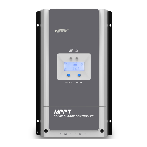
Figure 1-1 Tracer-AN Series Characteristics Item Name Item Name Charging LED indicator PV reverse polarity alarm indicator Diesel generator relay enable Load control relay enable ② RS485 port SELECT button Fuse Diesel generator relay ③ Battery Terminals RBVS Port PV Terminals ENTER button ①... - Page 8 The MPPT algorithm of our company continuously compares and adjusts the operating points to attempt to locate the maximum power point of the array. The tracking process is fully automatic and does not need user adjustment. As the Figure 1-2, the curve is the characteristic curve of the array, the MPPT technology will boost the battery charge current through tracking the MPP.
-
Page 9: Battery Charging Stage
appear Multi-MPP, but in actually there is only one real Maximum Power Point. As the below Figure 1-3 shows: Figure 1-3 Mutil-MPP Curve If the program works improperly after appearing Multi-MPP, the system will not work on the real max. power point, which may waste most solar energy resources and seriously affect the normal operation of the system. - Page 10 A) Bulk Charging In this stage, the battery voltage has not yet reached constant voltage (Equalize or Boost Voltage), the controller operates in constant current mode, delivering its maximum current to the batteries (MPPT Charging). B) Constant Charging When the battery voltage reaches the constant voltage setpoint, the controller will start to operate in constant charging mode, this process is no longer MPPT charging, and in the meantime the charging current will drop gradually, the process is not the MPPT charging.
- Page 11 battery. NOTE: 1) Due to the influence of ambient circumstance or load working, the battery voltage can’t be steady in constant voltage, controller will accumulate and calculate the time of constant voltage working. When the accumulated time reach to 3 hours, the charging mode will turn to Float Charging.
-
Page 12: Installation
2 Installation 2.1 General Installation Notes Before installation, please read through the entire installation instructions to get familiar with the installation steps. Be very careful when installing the batteries, especially flooded lead-acid battery. Please wear eye protection, and have fresh water available to wash and clean any contact with battery acid. - Page 13 point voltage (V ) of the MPPT controller, the series number of different types PV modules can be calculated. The below table is for reference only. Tracer8415AN: 36cell 48cell 54cell 60cell System Voc<23V Voc<31V Voc<34V Voc<38V voltage MAX. Best MAX. Best MAX.
-
Page 14: Mounting
When the PV array straight polarity, the actual operation of the PV array must NOT exceed three times of rated charge power;When the PV array reverse polarity, the actual operation must NOT exceed 1.5 times. For real application please refer to the table below: Rated Max. -
Page 15: Wiring
2.4 Wiring ※Please remove the terminal protective cover before wiring. CAUTION: The following connection order is recommended for optimal safety. CAUTION: Do not entangle all wiring together. Communication cable and power wires should be as far as possible to avoid interfering communication signal transmission. - Page 16 The included remote temperature sensor is recommended for effective temperature compensated charging. Connect the RTS to the7 port on the controller (Check Figure 1-1). The cable standard length is 3 meters and could be customized. There is no polarity, so either wire (+ or -) can be connected to either screw terminal.
- Page 17 Model Max. PV input current Max. PV wire size Tracer8415AN 25mm /4AWG Tracer10415AN 100A 35mm /2AWG NOTE: When the PV modules connect in series, the open circuit voltage of the PV array must not exceed 138V under the 25℃ condition. ...
- Page 18 Figure 2-2 Multi-machine Wiring Diagram Battery Connection Connecting a fuse in series through battery positive (+) in the circuit and the battery circuit fuse must be 1.25 to 2 times to the rated current. Keep OFF before connection. Connect battery positive (+) and negative (-) to battery terminals on the controller in the figure 1-1.
-
Page 19: Power Up
WARNING: Risk of explosion or fire! Never short circuit battery positive (+) and negative (-) or cables. Pay more attention to it 2.5 Power Up CAUTION: The controller is only powered by battery, so it will not work when connected only to solar input. ... -
Page 20: Indicator
3.1 Indicator Indicator Color Status Instruction PV connection normal but low Green On Solid voltage(irradiance) from PV, no charging No PV voltage(night time) or Charging LED Green PV connection problem indicator Slowly Flashing In charging Green Green Fast Flashing PV Over voltage Normal Fault LED Over discharged... - Page 21 PV Voltage, Current, Power Battery Battery capacity, In Charging Battery Voltage, Current, Temperature Battery Type Fault Indication Status Icon Description Battery level shows empty, battery Battery over discharged frame blink, fault icon blink Battery level shows full, battery frame Battery over voltage blink, fault icon blink Battery over...
-
Page 22: Battery Type
3.4 Battery Type Operating Steps Under Battery Voltage interface, long press ENTER button enter into the interface of Battery type setting. After choosing the battery type by pressing SELECT button, waiting for 5 seconds or pressing ENTER button again to modify successfully. ... - Page 23 Discharging Limit Voltage. e. Boost Reconnect Charging voltage > Low Voltage Disconnect Voltage. CAUTION: Please refer to user guide or contact with the sales for the detail of setting operation.
-
Page 24: Protections, Troubleshooting & Maintenance
4 Protections, Troubleshooting & Maintenance 4.1 Protections PV Over Current The controller will limit charge power in rated charge power. An over-sized PV array will not operate at maximum power point. PV Short Circuit When PV short circuit occurs, the controller will stop charging. Clear it to resume normal operation. -
Page 25: Troubleshooting
damaged from overcharging or over discharged. Controller Overheating If the temperature of the controller heat sinks exceeds 85℃, the controller will automatically start the overheating protection and recover below 75℃. High Voltage Transients PV is protected against small high voltage surge. In lightning prone areas, additional external suppression is recommended. - Page 26 Check all the naked wires to make sure insulation is not damaged for serious solarization, frictional wear, dryness, insects or rats etc. Repair or replace some wires if necessary. Tighten all the terminals. Inspect for loose, broken, or burnt wire connections.
-
Page 27: Specifications
5 Specifications Electrical Parameters Item Tracer8415AN Tracer10415AN Nominal System Voltage 12/24/36/48VDC Auto 8V~68V Battery Input Voltage Range Rated charge current 100A 150V (At minimum operating environment temperature) Max. PV open circuit voltage 138V (At 25℃ environment temperature) ① (Battery voltage+2V)~108V MPP Voltage Range 1050W/12V;... -
Page 28: Disclaimer
6 Disclaimer This warranty does not apply under the following conditions: Damage from improper use or use in an unsuitable environment. PV or load current, voltage or power exceeding the rated value of controller. The controller is working temperature exceed the limit working environment temperature. -
Page 29: Annex I Dimensions
Annex I Dimensions Tracer8415AN Dimensions(Unit:mm)... - Page 30 Tracer10415AN Dimensions(Unit:mm) Any changes without prior notice! Version number:V1.0...
- Page 32 BEIJING EPSOLAR TECHNOLOGY CO., LTD. Tel: +86-10-82894112 / 82894962 Fax: +86-10-82894882 E-mail:info@epsolarpv.com Website: http://www.epsolarpv.com/ http://www.epever.com/...
Need help?
Do you have a question about the Tracer-AN Series and is the answer not in the manual?
Questions and answers