Sign In
Upload
Download
Table of Contents
Contents
Add to my manuals
Delete from my manuals
Share
URL of this page:
HTML Link:
Bookmark this page
Add
Manual will be automatically added to "My Manuals"
Print this page
×
Bookmark added
×
Added to my manuals
Manuals
Brands
PIETRO FIORENTINI Manuals
Controller
FE Series
Manual
PIETRO FIORENTINI FE Series Manual
Low-pressure gas regulator
Hide thumbs
1
2
3
4
5
Table Of Contents
6
7
8
9
10
11
12
13
14
15
16
17
18
19
20
21
22
23
24
25
26
27
28
29
30
31
32
33
34
35
36
37
38
39
40
41
42
43
44
45
46
47
48
49
50
51
52
53
54
55
56
57
58
59
60
61
62
63
64
65
66
67
68
69
70
71
72
73
74
page
of
74
Go
/
74
Contents
Table of Contents
Bookmarks
Table of Contents
Introduction
Revision History
Table of Contents
General Information
Manufacturer Identification
Identification of the Product
Regulatory Framework
Warranty
Addressees, Supply and Storage of the Manual
Language
Symbols Used in the Manual
Nameplates Applied
Glossary for Nameplates
Glossary of Measurement Units
Qualified Professional Figures
Safety
General Safety Instructions
Personal Protective Equipment
Residual Risks
Table of Residual Risks for Potentially Explosive Atmospheres
Obligations and Prohibitions
Safety Pictograms
Risk Level
Description and Operation
General Description
Operation
Intended Use
Envisaged Use
Reasonably Foreseeable Misuse
Types of Fluids
Models and Configurations
Surface Treatments
Technical Features/Performance
Safety Devices
Slam-Shut Valve for Maximum Downstream Pressure
Excess Flow Lock-Up Device
Relief Valve
Pressure Outlet
Procedure of Use with Standard Pressure Outlet
Procedure of Use with Peterson Model Pressure Outlet
Transport and Handling
Specific Warnings for Transport and Handling
Packaging and Fasteners Used for Transport
Physical Characteristics of the Equipment
Equipment Anchoring and Lifting Method
Forklift Handling Method
Packaging Removal
Packaging Disposal
Storage and Environmental Conditions
Storage Lasting Longer than the Maximum Time Allowed
Installation
Installation Pre-Requisites
Allowed Environmental Conditions
Storage Lasting Longer than the Maximum Time Allowed
Checks before Installation
Specific Safety Instructions for the Installation Step
General Information on the Line
Installation Procedures
Post-Installation Instructions
Equipment Adjustments
Commissioning
General Warnings
Safety Requirements for Commissioning
Preliminary Procedures for Commissioning
Calibration of Safety Devices
Commissioning the Regulator
Commissioning the Regulator with Manual Reset
Commissioning the Regulator with Automatic Reset
Proper Commissioning Check
Reset of Safety Devices after Commissioning
Drum Assembly (Underground Version of the Regulator)
Drum Assembled to the Slam-Shut Valve Lid
Regulator Reset
Drum Fixed on the Second Stage Control Head
Functional Checks
General Warnings
Periodically Checking and Inspecting the Equipment for Proper Operation
Functional Checks of Safety Devices
Tightening Torques
Uninstallation and Disposal
General Safety Warnings
Qualification of the Operators in Charge
Uninstallation
Information Required in Case of New Installation
Disposal Information
Calibration Tables
Advertisement
Quick Links
1
Introduction
2
Description and Operation
3
Equipment Adjustments
Download this manual
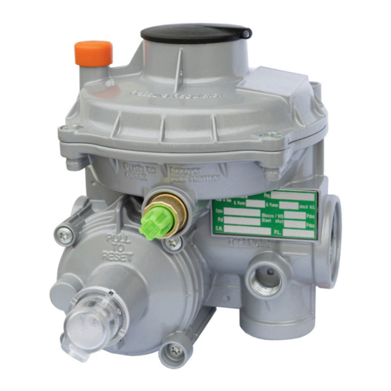
Series FE
Low-pressure gas regulator
Revision 00 - Edition 10/2021
USE, MAINTENANCE
AND WARNING
MANUAL
EN
Table of
Contents
Previous
Page
Next
Page
1
2
3
4
5
Advertisement
Table of Contents
Need help?
Do you have a question about the FE Series and is the answer not in the manual?
Ask a question
Questions and answers
Related Manuals for PIETRO FIORENTINI FE Series
Controller PIETRO FIORENTINI FE25 Use & Maintenance
Low-pressure gas regulator (70 pages)
Controller PIETRO FIORENTINI FEX Series Technical Manual
Low-pressure gas regulator (74 pages)
Controller PIETRO FIORENTINI FE6 Manual
Low-pressure gas regulator (74 pages)
Controller PIETRO FIORENTINI FE10 Manual
Low-pressure gas regulator (74 pages)
Controller PIETRO FIORENTINI FE50 Use & Maintenance
Low-pressure gas regulator (70 pages)
Controller PIETRO FIORENTINI FE75 Use, Maintenance And Installation Manual
Low-pressure gas regulator (66 pages)
Controller PIETRO FIORENTINI FT 518 Use & Maintenance
High-medium pressure gas regulator (230 pages)
Controller Pietro Fiorentini REFLUX 819/FO Technical Manual
Pressure regulator (93 pages)
Controller Pietro Fiorentini NORVAL Installation, Commisioning And Maintenance Instructions
Pressure regulator (59 pages)
Controller Pietro Fiorentini Dival 600 Technical Manual
Pressure regulator (28 pages)
Controller Pietro Fiorentini APERFLUX 101 Technical Manual
Pressure regulator (37 pages)
Controller Pietro Fiorentini REFLUX 819 Technical Manual
Pressure regulator (87 pages)
Controller PIETRO FIORENTINI Dival SQD-1 Technical Manual
Pressure regulators (36 pages)
Controller PIETRO FIORENTINI REVAL 182 Technical Manual
Pressure regulator (84 pages)
Controller PIETRO FIORENTINI Dixi Series Technical Manual
Pressure regulator (52 pages)
Controller PIETRO FIORENTINI NORVAL Technical Manual
Pressure regulator (53 pages)
This manual is also suitable for:
Fe6
Fe10
Fe25
Fes
Table of Contents
Save PDF
Print
Rename the bookmark
Delete bookmark?
Delete from my manuals?
Login
Sign In
OR
Sign in with Facebook
Sign in with Google
Upload manual
Upload from disk
Upload from URL


Need help?
Do you have a question about the FE Series and is the answer not in the manual?
Questions and answers