
Related Manuals for PIETRO FIORENTINI Dival SQD-1


Summary of Contents for PIETRO FIORENTINI Dival SQD-1
- Page 1 Pressure Regulators Dival SQD-1 TECHNICAL MANUAL INSTALLATION ,COMMISSIONING AND MAINTENANCE ISTRUCTIONS...
- Page 3 Poster Dival SQD-1 Inlet pressure Outlet pressure Dival SQD-1 - MT 234-E - 02-2020...
- Page 4 (PS). Therefore, the user, as deemed necessary by the same, shall install on the assembly suitable pressure limitation sy- stems, as well as provide the plant with suitable relief or drain systems in order to discharge the pressure and fluid contained in the plant before proceeding with any inspection and maintenance activity. If the installation of the apparatus requires the application of compression fittings in the field, these must be installed following the instructions of the manufacturer of the fittings themselves. The choice of the fitting must be compatible with the use specified for the apparatus and with the specifications of the system when envisaged.. START UP Commissioning must be carried out by adequately trained personnel. During the commissioning activities, the personnel not strictly necessary must be ordered away and the no-go area must be properly signalled (signs, barriers, etc.). Check that the settings of the apparatus are those requested; if necessary, reset them to the required values in accor- dance with the procedures indicated in the manual. When commissioning, the risks associated with any discharges into the atmosphere of flammable or noxious gases must be assessed. In installations in natural gas distribution networks, the risk of the formation of explosive mixtures (gas/air) inside the piping must be considered. COMPLIANCE WITH DIRECTIVE 2014/68/EU (PED) The SQD-1 regulators are classified as Fail Open regulators and as Integral Strength (IS) according to EN 334 and are therefore definied as safety accessories according to Directive 2014/68/EU (PED). Dival SQD-1 - MT 234-E - 02-2020...
-
Page 5: Table Of Contents
INTRODUCTION Main features Operation of the pressure regulator SQD-1 Setting springs INSTALLATION General Connecting the apparatuses Downstream volume required for installation MODULARITY’ LA/.. Incorporated slam-shut LA/.. Slam-shut setting springs ACCESSORIES Relief Valve 4.1.1 Direct installation in the line 4.1.2 Installation START UP General Gas input, control of external tightness and setting Commissioning the regulator Commissioning the regulator with incorporated LA/..Slam-shut TROUBLE-SHOOTING Table 5 regulator SQD 100 Table 6 slam-shut MAINTENANCE General SQD 100 regulator maintenance procedure Replacement filter LA/.. Slam-shut valve FINAL OPERATION Checking the tightness and setting Start up Dival SQD-1 - MT 234-E - 02-2020... -
Page 6: Introduction
If, during operation, the downstream pressure drops, the force it exerts on the diaphragm 19 becomes lower than the load of the spring 43. The diaphragm therefore drops and, by means of the lever system 13, pulls the obturator 3 away from the valve seat 2. The gas flow, therefore, increases until the initial pressure set-point is restored. If, on the other hand, the downstream pressure begins to increase, the force exerted on the diaphragm 19 exceeds the load the spring 43. The obturator is therefore displaced towards the closed position, returning the downstream pressure the set-point. In normal working conditions, the obturator 3 is positioned in such a way as to maintain the pressure Pd around the selected set-point. To adjust the pressure set-point you con turn the internal adjustment ring 28 appropriately, clockwise to increase and anticlockwise to reduce it. Normally the plug is only used the cover the lower band of the various setting ranges; the adjusting screw is used for the higher values. The pressure regulator is equipped with two anti-pumping devices 33 and 34 (fig. 1), which are in charge of slowing down the inflow/outflow of the gas/air in the head only during the transitory phases, in order to avoid possible oscillation phenomena of the regulated pressure. There are also two stops V1 and V2 for the purpose of eliminating damaging effects which could derive from accidental over-pressures below the diaphragm 19 or from overloading of the spring 43. Usually, a solution of the type shown in fig. 2a is adopted in order to protect the obturator against damages resulting from sudden increases of the regulated pressure. Dival SQD-1 - MT 234-E - 02-2020... - Page 7 DESCRIPTION 33 33 19 19 13 13 43 43 28 28 46 46 34 34 48 48 SQD-1 Pressure regulator: Fig. 1 In fact, this solution allows the diaphragm protection disc 20 to rest on the upper stroke end V1 exceeding the load of the spring 42 and thus releasing the obturator from the load resulting from the sudden pressure increase. In order to prevent small leaks at null required flow rate or that sudden and temporary overpressures, re- sulting for example from fast manoeuvres or gas overheating, may let the slam-shut valve trip, the solution shown by fig. 2a can be transformed, upon request, into an embedded relief valve, eliminating the O-ring 73 and adding the ring 70 (fig. 2b). Its operation is described as follows: with closed regulator, any overpressures lift the diaphragm protection disc 20 exceeding the load of the springs 42 and 43. In this way, a given quantity of gas is discharged through the seat Z of the relief valve. Dival SQD-1 - MT 234-E - 02-2020...
-
Page 8: Setting Springs
64470031RO 64470140MA BROWN 36 - 65 64470031RO 64470071GR GREY 66 - 100 64470031RO De = external diameter d = wire diameter Lo = length * = for internal relief valve Springs Tab. 2 SPRINGS CHARACTERISTICS SQD 100 MP Code Colour Setting range (mbar) 64470141VE GREEN 101 - 170 64470038GI YELLOW 64470329AZ LIGHT BLUE 171 - 300 64470038GI YELLOW De = external diameter d = wire diameter Lo = length * = for internal relief valve Springs Tab. 2 Dival SQD-1 - MT 234-E - 02-2020... -
Page 9: Installation
INSTALLATION INSTALLATION GENERAL Pressure regulator does not require any supplementary upstream safety accessory for protection against overpressu- re compared with its design pressure PS, when upstream reducing station is sized for a max downstream incidental MI Pd ≤ 1,1 PS. pressure Before installing the regulator it is necessary to ensure that: - The regulator can be inserted in the space provided and that subsequent maintenance operations will be sufficien- tly practicable (see overall dimensions in Fig. 3); - Inlet and outlet pipings must be at the same level and able to carry the weight of the regulator (see Fig. 3); - The inlet/outlet flanges of the piping are 90°l; - The inlet/outlet flanges of the regulator are clean and the regulator itself has not been subject to damage during transport; - The piping upstream has been cleaned to expel residual impurities such as welding scale, sand, paint residues, water, etc. The usually foreseen arrangement is the one indicated in figure 4. 330,5 Pressure regulators without slam-shuth: Kg.13 Pressure regulators with slam-shut: Kg. 14 Overall dimensions and weights: Fig. 3 Dival SQD-1 - MT 234-E - 02-2020... -
Page 10: Connecting The Apparatuses
INSTALLATION CONNECTING THE DEVICES The connections between the apparatus and the main piping must be made using stainless steel or cooper pipe with minimum internal diameter of 8 mm. Pressure regulator Contol pressure gauge Bleed cock On/off valve Installation scheme: Fig. 4 Detail of multiple take-off: Fig. 5 Dival SQD-1 - MT 234-E - 02-2020... -
Page 11: Downstream Volume Required For Installation
LA/.. INCORPORATED SLAM SHUT This is a device (fig. 7 and 8) which immediately blocks the gas flow if, because of some failure, the downstream pres- sure reaches the point set for its intervention, or if it is actuated manually. Wait the SQD-1 pressure regulator, the slam-shut be incorporated on both the service regulator or on the in-line mo- nitor. Three versions (LA/BP, LA/MP and LA/TR) are available depending on the intervention pressure ranges The main features of the slam-shut device are as follows: • Design pressure PS: up to 20 bar; • Intervention for pressure increase and/or decrease; • Intervention accuracy AG: ± 5% of the set point for pressure increase (based on setting-pressure); ± 15% of the set point for pressure drop (based on setting-pressure); • internal by-pass device; • manual button-operated actuating device. N.B. WE RECOMMEND NOT TO PUT ON/OFF VALVES ON THE IMPULSE TAKE-OFFS ATTENTION! Dival SQD-1 - MT 234-E - 02-2020... - Page 12 INSTALLATION General Lay-out: Fig. 6 Detail of manual button operated actuating de- vice N.B.: L’O-ring is used for specific version. LA/...Slam-shut: Fig. 7 Dival SQD-1 - MT 234-E - 02-2020...
- Page 13 GREY 50 ÷ 180 Intervention for min. pressure 64470024BI WHITE 6 ÷ 60 LA/MP SLAM-SHUT SPRING CHARACTERISTICS Code Colour Setting range in mbar Intervention for max. pressure 64470115GR GREY 140 ÷ 180 64470116GI YELLOW 180 ÷ 280 64470051BI WHITE 280 ÷ 450 Intervention for min. pressure 64470024BI WHITE 10 ÷ 60 6470038GI YELLOW 60 ÷ 240 De = external diameter d = wire diameter Lo = Length LA/.. Slum-Shut Tab. 3 Dival SQD-1 - MT 234-E - 02-2020...
-
Page 14: Accessories
INSTALLATION ACCESSORIES RELIEF VALVE The relief valve is a safety device which releases a certain quality of gas to the exterior when the pressure at the con- trol point exceeds the set-point as a result of short-lasting events such as, for example, the very fast closing of the on/ off valves and/or overheating of the gas with zero flow rate demand. The release of the gas to the exterior can, for example, delay or block the intervention of the slam-shut valves for transitory reasons deriving from damage to the regulator. Obviously the quantity of gas released depends on the extent of the overpressure with respect to the set-point. The different models of relief valves available are all based on the same operating principle which is illustrated below with reference to the valve VS/AM 65 (fig. 8). It is based on the contrast between the thrust on the diaphragm 24 deriving from the pressure of the gas to control and the thrust from the setting spring 20. The weight of the mobile as- sembly, the static thrust and the residual dynamic thrust on the obturator 4 also contribute to this contrast. When the thrust deriving from the pressure of the gas exceeds that of the setting spring, the obturator 4 is raised and a certain quality of gas is released as a result. As soon as the pressure drops below the set-point, the obturator returns to the closed position. Proceed as indicated below to control and adjust intervention of the relief valve. VS/AM65: Fig. 8 4.1.1 DIRECT INSTALLATION IN THE LINE (fig. 9). When the relief valves fitted directly in the line that is, without the interposition of an on/off valve, we recommend proceeding as follows: Ensure that the downstream on/off valve V2 and the bled cock 6 are closed; Connect to the cock 6 a controlled auxiliary pressure and stabilize it to the wished tripping value of the relief valve. Open the bleed cock 6 with a following increase in the pressure of the downstream section; Check intervention of the relief valve and ad just it if necessary by turning the internal adjustment ring 14 appropriately (clockwise to increase the set-point, anticlockwise to reduce it). Dival SQD-1 - MT 234-E - 02-2020... -
Page 15: Installation
INSTALLATION Direct installation: Fig. 9 4.1.2 INSTALLATION WITH ON/OFF VALVE (fig. 10) Close the on/off valve 16; Connect a controlled auxiliary pressure to the take-off valve 17 and increase it slowly to the envisaged inter- vention value; Check intervention of the relief valve and ad just it if necessary by turning the interna adjustment ring 14 appropriately (clockwise to increase the set-point, anticlockwise to reduce it). Installation With On/Off Valve : Fig. 10 START UP GENERAL After installation, check that the inlet/outlet on/off valves, any by-pass and the bleed cock are closet. Before commissioning, you must ensure that the conditions of use comply with the characteristics of the apparatu- ses. These characteristics are recalled by the symbols on the specification plates applied to each apparatus (fig. 11). We recommend actuating the opening and closing valves very slowly. The regulator could be damaged by operations which are too fast. Dival SQD-1 - MT 234-E - 02-2020... -
Page 16: Gas Input, Control Of External Tightness And Setting
Wdo= range of intervention for the over pressure of slam-shut which can be obtain using the setting springs indi- cated in the tables. Wdsu= range of intervention for pressure decrease of slam-shut which can be obtain using the setting spring fitted at the moment of testing. Wdu= range of intervention for pressure decrease of slam-shut which can be obtain using the setting springs indi- cated in the tables. GAS INPUT, CONTROL OF EXTERNAL TIGHTNESS AND SETTING The pressurization of the equipment shall be performed very slowly. Should not any stabilization procedure be carried out, it is recommended to keep gas speed in the feeding piping at a value equal to 5 m/sec during pressurization. To protect the apparatus from damage, the following operations must never be carried out: • Pressurization through a valve located downstream from the apparatus itself. • Depressurization through a valve located upstream from the apparatus itself. External tightness is guaranteed if no bubbles form when a foam medium is applied on the element under pressure. The regulator and any other apparatuses (slam-shut, monitor) are normally supplied already set for the desired set- point. It is possible for various reasons (e.g., vibration during transport) for the settings to be changed while remaining within the values permitted by the springs used. We therefore recommend checking the settings using the procedures illustrated below. In installation consisting of two lines, we suggest commissioning one line at a time, starting from the one with the lover set-point, known as the “reserve” line. The set-point of the apparatuses in the line will obviously deviate from those specified in the table 4. Dival SQD-1 - MT 234-E - 02-2020... -
Page 17: Commissioning The Regulator
INSTALLATION Before commissioning the regulator you must check that all the on/off valves (inlet, outlet, any by-pass) are closet and that the gas is at a temperature which will not lead to malfunction. COMMISSIONING THE REGULATOR If there is also a relief valve in the line, refer to par. 4.1 to check it Fig. 12 partially open the downstream bleed cock 6; very slowly open the inlet on/off valve V1; stabilize pressure upstream and downstream; through the pressure gauge 5 check that the downstream pres- sure shows the wished calibration value. Otherwise, adjust the calibration acting on the proper internal ring nut (fig. 1), rotating it clockwise to increase and counter-clockwise to decrease; close the bleed cock 6 and verify the tightness of the regulator and the value of its closing overpressure; check the tightness of all the joints between the on/off valves V1 and V2 using a foam Solution; very slowly open the downstream on /off valve V2, until the line is completely filled. COMMISSIONING THE REGULATOR WITH INCORPORED LA/.. SLAM-SHUT If there is also a relief valve in the line, refer to par. 4.1 to check it. Fig. 13 Dival SQD-1 - MT 234-E - 02-2020... - Page 18 • for safety devices which intervene for pressure increase and reduction: slowly increase the auxiliary ressure and record the intervention value. Restore the pressure to the set point established for the regula- tor, and carry out slam-shut reset operation. - Check intervention for pressure reduction by slowly reducing the auxiliary pressure. If necessary, increase the ntervention values for pressure increase or decrease by respectively turning the rings 18 and 17 clockwise and vice-versa to reduce them. - check proper operation by repeating the operations at least 2-3 times. Rest position (A and B communication) Cham- ber with Controll position controlled (A and C communication) pressure Enviroment with the pressare to keep under control Fig. 14 B) On devices without the “push” valve (fig. 15) we recommend connecting the control head separately to a con- trolled auxiliary pressure and repeating the operations described above Chamber with control- led pressure Enviroment with the pressare to keep under control Fig. 15 Dival SQD-1 - MT 234-E - 02-2020...
-
Page 19: Trouble-Shooting
(Pds) mbar 10<Pds≤15 Slam-shut not available Pds x 1.7 Pds x 2 15<Pds≤19 10 mbar 19<Pds≤24 Pds x 0.56 24<Pds≤35 Pds x 1.77 Pds x 0.57 Pds x 1.55 35<Pds≤40 Pds x 1.7 40<Pds≤70 Pds x 1.4 Pds x 1.52 70<Pds≤80 Pds x 0.6 80<Pds≤100 Pds x 1.3 Pds x 1.4 100<Pds≤300 Setting of on-line apparatuses consisting of regulators SQD-1 + Slam-shut + Relief valves Tab. 4 TROUBLE-SHOOTING The problems of various kinds which could arise over time are highlighted below. They derive from phenomena asso- ciated with the conditions of the gas as well, of course, as with the natural ageing and wear of the materials. It must be remembered hat all operations on the apparatuses must be carried out by highly qualified personnel with appropriate knowledge of the subject. Tampering with the apparatuses by unsuitable personnel relieves us from all responsibility of any kind. You must therefore train your maintenance personnel or avail yourself of the service centres officially authorised by Dival SQD-1 - MT 234-E - 02-2020... - Page 20 Friction in lever systems Change Persistence of the cause which led to pres- Decrease or decrease the down- Rearming not sure increase or decrease downstream stream pressure possible Lever systems broken or chipped Change Tab. 6 N.B. If the slam-shut has intervened, close the inlet and outlet valve (V1 and V2) in the line and discharge the pressure before carrying out any operation. Eliminate the causes which gave rise to intervention before reactivating it. In the event of operating problems when personnel qualified for a specific operation are not available, call the service centre nearest to you. For further information contact our SATRI service centre at our Arcugnano (Vicenza) works Dival SQD-1 - MT 234-E - 02-2020...
-
Page 21: Maintenance
Before carrying out any operation it is important to ascertain that the regulator has been cut off both upstream the regulator and the on/off valves. The maintenance operations are closely associated with the quality of the gas tran- sported (impurities, humidity, gasoline, corrosive substances) and with the efficiency of the filtering. Preventive maintenance should be carried out at intervals which, if not established by regulation in force, depend The quality of the gas transported; The cleanliness and conservation of the piping upstream from the regulator: in general, for example, when starting the equipment for the first time, more frequent maintenance is required because the precarious state of cleanliness inside the piping; The level of reliability required from the regulation system. Before starting the disassembly operations on the apparatus you should check that: A set of recommended spares is available. The spares must be original Fiorentini ones, bearing in mind that the more important ones such as diaphragms are marked; A set of wrenches is available as specified in table 7. For a proper maintenance the recommended spare arts are unequivocally identified by labels indicating: The No of assembly drawing SR of the apparatus for which the spare parts are suitable; The position showed in the assembly drawing SR of the apparatus. We advise to replace all rubber-made parts. In order to do this, please use the appropriate replacing kit. N.B. Pietro Fiorentini S.p.A. is in no case responsible, in case of use of non-original replacements. Before starting disassembling the equipment, it is also necessary to make sure that the plant section on which one is working is not operating upstream or downstream, as well as that the pressure in the involved piping section has been discharged. The depressurization manoeuvre has to be carried out paying attention to discharge the bleed cocks to the drains in a safe area. To avoid the risk of generating sparks due to bumps of impurity particles within the discharge lines, it is recommended to keep the fluid speed lower than 5 m/sec. Moreover, it is suggested to perform reference marks, before disassembling the equipment, on the parts that may show problems of mutual orientation or positioning during re-assembly. Finally, it shall be underlined that the O-rings and the mechanical sliding parts (stems, etc.) must be lubricated, before re-assembling them, with a thin layer of silicone grease. Before commissioning, the external tightness of the equip- ment has to be tested at a suitable pressure in order to assure the absence of external leaks. The internal tightness of the block devices and of the monitors, when these are used as safety accessories according to the PED Directive, has to be tested at a suitable pressure in order to assure the internal tightness at maximum foreseen operating pressure. Such tests are essential to assure the safe use under the foreseen operating conditions. They have in any case to comply with the national regulations in force. Dival SQD-1 - MT 234-E - 02-2020... -
Page 22: Sqd 100 Regulator Maintenance Procedure
MAINTENANCE SQD-1 REGULATOR MAINTENANCE PROCEDURE Device status: installed and disconnected from gas grid Authorized personnel: maintainer Necessary equipment: see “Tab.7” Preliminary Operation: • Ensure that the pressure upstream and downstream from it is 0 • On the axis of the regulator, tick with a permanent marker the joints of the different elements. This action acts as a guide and help the later reassembling phase. SQD-1 Pressure regulators Fig. 16 Dival SQD-1 - MT 234-E - 02-2020... - Page 23 MAINTENANCE Spring extractiong: Fig. 17 2. Completely unscrew the tap (326) and the internal regulating clamp (318). Then take out the spring (328); Remove low support cap: Fig. 18 3. Remove the screws (314) that fix the low support cap (301) with the high support cap (312); Remove cap: Fig. 19 4. Remove the high cap (312); Dival SQD-1 - MT 234-E - 02-2020...
- Page 24 MAINTENANCE Nut extractiong: Fig. 20 5. Remove the screw-nut (311) and extract the spring holder (31). Nut extractiong: Fig. 21 6. Unscrew the screw-nut (324). Membrane extractiong: Fig. 22 7. Dismantle the protection disc (323), the membrane (322) and the membrane-support (321); Dival SQD-1 - MT 234-E - 02-2020...
- Page 25 MAINTENANCE Check internal levers: Fig. 23 8. Check, by increasing and decreasing, the correct functioning of the internal levers (305); Screws extractiong: Fig. 24 9. Take the screws out (46) Fig. 25 Head and balancing group extractiong : 10. Separate the head (300) and the balancing group (200) from the regulator’s body (1); Dival SQD-1 - MT 234-E - 02-2020...
- Page 26 MAINTENANCE Fig. 26 Balancing group extractiong : 11. Separate the balancing group (200) from the head (300) by modifying the flowing-direction of the gas in order to get the shaft (308) getting out of the loading joint (212); alancing group disassembling Fig. 27 12. Unscrew the screw (214) from the obturator (211) and separate alll the components of the balancing group (200); Valve seat Fig. 28 extractiong: 13. Unscrew the valve seat from the body (2), paying attention not to damage the sustain rims; Dival SQD-1 - MT 234-E - 02-2020...
- Page 27 MAINTENANCE Slam-shut screw extractiong: Fig. 29 14. Unscrew the screws (48). Slam-shut extractiong : Fig. 30 15. Remove the slam-shut valve with pad Dival SQD-1 - MT 234-E - 02-2020...
- Page 28 MAINTENANCE Slam shut flange removal: Fig. 31 16. Unscrew and remove the screw [48] and remove the flange [556] To re-install the regulator you can carry out the operations described for the dismantling, in the opposite way. Before re-installing the sustain elements (o-rings, membranes, etc…), it is necessary to check their integrity and if that is the case to replace them. It is necessary to make sure that the membrane (209) is perfectly inserted in its seat and that the movement of the shaft-obturator group shows no obstruction. You have to be very careful in manipulating the valve seat (2), not to damage the sustain rims. The internal regulation clamp (318) must be only partially activated. The maintenance just of the regulation valve (balancing group 300 and valve seat 2) can be carried out without having to intervene on the control head. In this case, the operations to be followed start from position 9 after having implemented the position 1 opera- tion. Dival SQD-1 - MT 234-E - 02-2020...
-
Page 29: Replacement Filter
MAINTENANCE FILTER REPLACEMENT Device status: installed and disconnected from gas grid Authorized personnel: maintainer Necessary equipment: see “Tab.7” Cover removal: Fig. 32 Unscrew and remove screws from cover Cover removal: Fig. 33 2. Pull out the cover; Dival SQD-1 - MT 234-E - 02-2020... - Page 30 MAINTENANCE Filter cartridge replacement: Fig. 34 3. Pull out filter cartridge. Dival SQD-1 - MT 234-E - 02-2020...
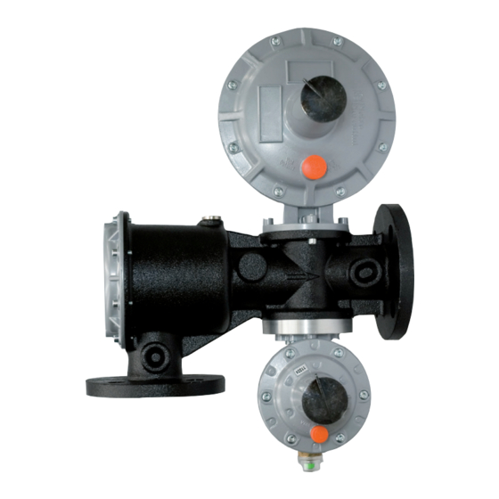
- Page 31 MAINTENANCE Pressure regulator: Fig. 35 Dival SQD-1 - MT 234-E - 02-2020...
- Page 32 MAINTENANCE Standard head: Fig. 36 206b 203b Balance: Fig. 37 Dival SQD-1 - MT 234-E - 02-2020...
- Page 33 VLA/:: SLAM SHUTH VALVE (fig. 38) 1) Make sure that the slam-shut valve is in closed position; 2) Disconnect the fittings between the slam-shut valve and the downstream pressure connection; 3) Remove the screws tightening the slam-shut valve to the body; 4) Unscrew the plug (20) and the regulation nuts (17) and (18); then, extract the calibration springs (34) and (35) and the spring supports (12) and (13); 5) Remove the screws (41) and disassemble the cover (2) with the nut (14); 6) Extract from the body (1) the diaphragm assembly consisting of the parts 45, 46, 48, and 49; to separate them, unscrew the pin (45) from the tightening nut (49); 7) Remove the nut (37) and unscrew the nut (6) and the threaded bush (7) completely; 8) From the upper part, extract the shaft assembly consisting of the parts 9, 66, 19, 4 and 8, the bushes (22) and (23) and (19), and the shaft (5). Then, unscrew the shaft (5) and the obturator support (4), and remove the spring ring (9) to disassemble the obturator (19); 9) Remove the screws (40) and disassemble the anchoring assembly consisting of the parts 29, 30, 33, 36, 38, 39, and 10) Remove the screws (53) to disassemble the flange (51); 11) Finally, to disassemble the release button assembly, unscrew the nut (61) and then unscrew the part (58) from the pin (62). To reassemble the slam-shut it is possible to carry out the disassembly operations in the inverse order. Before reassembling the sealing elements (O-rings, diaphragms, etc.), check their integrity and replace them if neces- sary Blocco LA: Fig. 38 Dival SQD-1 - MT 234-E - 02-2020...
-
Page 34: Final Operation
MAINTENANCE FINAL OPERATION CHECKING THE TIGHTNESSES 1) Very slowly open the on/off valve upstream from the regulator and using a foam solution or the like check: • the tightness of the external surfaces of the regulator; • the tightness of the slam-shut; • the tightness of the internal surfaces of the regulator; • the tightness of the fitting. 2) Operating very slowly, pull the provided threaded bushing (7), off the slam-shut until only the internal by-pass is opened. Pull completely to the re-engage position; 3) Check the tightness of the reinforced gasket of the regulator; 4) Open a bleed cock downstream from the regulator to create a small gas flow; 5) Turn the internal adjustment ring (318) until the desired set-point value is reached; 6) Close the bleed cock to the atmosphere. START UP 1) Very slowly open the downstream on/off valve and, if necessary, ad just the regulator set-point by means of the internal adjustment ring (318). 2) Set the tap (326) for normal control head. Dival SQD-1 - MT 234-E - 02-2020... - Page 35 Below the table “Tools for maintenance” Type Tool Description Ch. 8-9-10-11-12-13-14-15- • Combination spanner 16-17-18-19-20-21-22-23- 24-25-26-27-41 • Adiustable spanner L. 30 Ch. 8-9-10-11-12-13-14-15- • Compass pin wrench 16-17-18-19-20-24-26-27- 36-46 • Hexagon or allen Key Ch. 3-4-5-6-7-8-19 Es.Ch PH 0 x 100 - PH 1x125 • Philips screwdriver PH 2x150 • Flat head screwdriver 0,5x3x75 1,2x6,5x125 • Circlip pliers Cod.10÷25 19÷60 Tab. 7 Dival SQD-1 - MT 234-E - 02-2020...
- Page 36 Via Enrico Fermi, 8/10 36057 Arcugnano (VI) Tel. +39 0444 968511 - Fax +39 0444 960468 mail: arcugnano@fiorentini.com - www.fiorentini.com...
Need help?
Do you have a question about the Dival SQD-1 and is the answer not in the manual?
Questions and answers