
Related Manuals for PIETRO FIORENTINI APERFLUX 101


Summary of Contents for PIETRO FIORENTINI APERFLUX 101
- Page 1 MT-208-E ENGLISH PRESSURE REGULATOR perflux TECHNICAL MANUAL INSTALLATION, COMMISSIONING AND MAINTENANCE INSTRUCTIONS | sales@mvandc.com | Phone: 877.566.3837 | Fax: 925.407.2903 www.mvandc.com...
- Page 2 Technical manual MT 208-E Pressure Regulator INLET PRESSURE OUTLET PRESSURE CONTROL PRESSURE | sales@mvandc.com | Phone: 877.566.3837 | Fax: 925.407.2903 www.mvandc.com...
- Page 3 Technical manual MT 208-E If the installation of the apparatus requires the application of PRECAUTION compression fittings in the field, these must be installed following the instructions of the manufacturer of the fittings themselves. The choice of the fitting must be compatible with the use specified for the GENERAL PRECAUTION apparatus and with the specifications of the system when envisaged.
-
Page 4: Table Of Contents
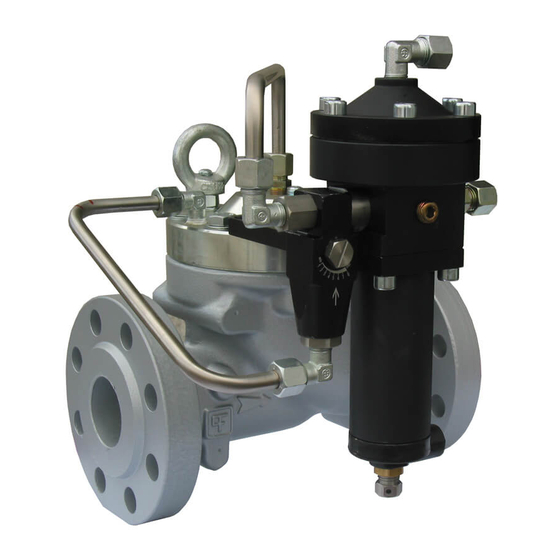
THE SERIES 300 PILOT AND SETTING PILOTS COMMISSIONING THE REGULATOR REGULATING VALVE COMMISSIONING THE REGULATOR APERFLUX 101 SETTING SPRINGS PLUS APERFLUX 101 IN-LINE MONITOR COMMISSIONING THE REGULATOR APERFLUX 101 PLUS REFLUX 819 IN-LINE MONITOR WITH INCORP. SB 82 13 INSTALLATION... - Page 5 MAIN FEATURES The APERFLUX 101 pressure regulator is a regulator for medium and high pressure. The APERFLUX 101 is a “fail open” type regulator and therefore opens in the event of: - rupture of the main diaphragm - no feed in the pilot circuit...
- Page 6 Technical manual MT 208-E PILOTS Pressure Regulators APERFLUX 101 use following type of pilots: 302/. setting range Wd: from 0,8 to 9,5 bar; (11,6 to 137,7 psig) 304/. setting range Wd: from 7 to 43 bar; (101,5 to 623,5 psig) 305/.
- Page 7 Technical manual MT 208-E AR/100 REGULATING VALVE Pilots series 300 are equipped with regulation valve AR 100 Fig.5 Tab 2: SETTING SPRINGS SPRING CHARACTERISTICS PILOT 302/A Code Color Setting range (bar) 2701800 YELLOW 0,8 ÷ 1,4 2702080 ORANGE 1,4 ÷ 2,4 2702290 2,4 ÷...
-
Page 8: General
Technical manual MT 208-E - the piping upstream has been cleaned to expel residual impurities INSTALLATION such as welding scale, sand, paint residues, water, etc. The usually foresee arrangement is one indicated in fig. 6. GENERAL Pressure regulator does not require any supplementary upstream safety accessory for protection against overpressure compared with its design pressure PS, when upstream reducing station is sized for a max downstream incidental pressure... - Page 9 Technical manual MT 208-E CONNECTING THE APPARATUSES Fig. 9: Detail of multiple Take-off The connections between the apparatus and the main piping must be made using stainless steel pipe with minimum internal diameter of 8 IN-LINE INSTALLATION Sensing line Contol pressure Pilot discarge Bleed cock On/off valve...
- Page 10 Technical manual MT 208-E Tab.5 The speed of the gas must not exceed the following values in the piping downstream from the regulator: Vmax = 30 m/s for Pd > 5 bar Vmax = 25 m/s for 0,5 < Pd ≤ 5 bar DOWNSTREAM VOLUME REQUIRED FOR INSTALLATION In the case of a service regulator of the ON-OFF type (stopping or...
- Page 11 Technical manual MT 208-E SB/82 SLAM-SHUT VALVE The SB/82 slam-shut device (see fig. 14-15) consists of an obturator A, a releasing lever system, a control head B and a resetting system which is controlled manually by the lever C. The pressure in the circuit to control acts on the diaphragm in the control head B.
-
Page 12: In Line Monitor
Technical manual MT 208-E APPARATUS SPECIFICATION PLATES IN LINE MONITOR The monitor is an emergency regulator whose function is to come into service instead of the main regulator when failure of the latter causes the downstream pressure to reach the point set for monitor intervention. -
Page 13: Commissioning The Regulator
COMMISSIONING REGULATOR In installation consisting of two lines, we suggest commissioning one APERFLUX 101 WITH APERFLUX 101 IN line at a time, starting from the one with the lover set-point, known as LINE MONITOR (fig.20) the “reserve” line. The set-point of the apparatuses in the line will obviously deviate from those specified in the table 6. -
Page 14: Commissioning The Regulator Aperflux
At the end of the operation, reconnect the control head to the downstream pressure take-off COMMISSIONING THE REGULATOR APERFLUX 101 WITH REFLUX 819 IN N.B.: The intervention test should be repeated at least every 6 monts. LINE MONITOR WITH INCORP. SB/82 SLUM-SHUT AND ACCELLERATING VALVE (fig.21) - Page 15 Chamber with controlled pressure Environment with the pressure to keep under control fig. 23 Setting of on-line apparatuses consisting of regulators Tab 6 APERFLUX 101+ Monitor + Slam-shut + Relief valves Reg. set-point Monitor Accelerator Relief valve Slam-shut Max Slam-shut Min...
-
Page 16: Trouble-Shooting
It must be remembered that all operations on the apparatuses must be carried out by highly qualified personnel with appropriate knowledge of the subject. Tab. 7 APERFLUX 101 REGULATOR (fig. 25, 26, 27, 28, 29) PROBLEM POSSIBLE CAUSE APPARATUS... -
Page 17: Maintenance
Procedure for the disassembly, complete replacement of the pressure has been discharged in the sections of piping between the spare parts and reassembly of the APERFLUX 101 pressure regulator and the on/off valves. regulator. - Page 18 Technical manual MT 208-E Take out the diaphragm group and separate the single parts (3 – Remove the pilot from the regulator 9 and 11) Remove the grill from the body (1) Remove the fixing bolts of the high cap (5) from the main body Remove the O-Ring (13) from the grill (2) Remove the O-Ring (4) from the body (1) Remove the high cap (5)
-
Page 19: Disassembling Unit 302/A Pilot
Technical manual MT 208-E To re-install the regulator you can carry out the operations described Remove the cap together with the spring and the spring guide for the dismantling, in the opposite way. Before re-installing the sustain elements (o-rings, diaphragm, etc…), it is necessary to check their integrity and if that is the case to replace them. - Page 20 Technical manual MT 208-E Unscrew the fixing nut Remove the head cap Remove the nut together with the disc and the diaphragm 10) Remove the spring and the diaphragm Loosen and remove the fixing bolts of the head cap to the flange 11) Remove the ring | sales@mvandc.com | Phone: 877.566.3837 | Fax: 925.407.2903 www.mvandc.com...
- Page 21 Technical manual MT 208-E 12) Loosen and remove the fixing bolts of the flange to the valve 15) Remove the diaphragm support together with the spring and body remove the o-rings 13) Remove the flange from the valve body 16) Remove the obturator together with the spring and the diaphragm Remove the valve seat group fitting 14) Unscrew the diaphragm support | sales@mvandc.com | Phone: 877.566.3837 | Fax: 925.407.2903...
- Page 22 Technical manual MT 208-E Unscrew and remove the fixing nut of the valve seat group to the Remove the valve seat and the inside components valve body Separate the valve seat group from the valve body and the diaphragm support Unscrew the valve seat from the valve seat group (3) valve seat group, (38) valve seat,(39) modular piston,(40) guide,(41) connector, (42) cylindrical pin.
-
Page 23: Disassembling Unit 304/A Pilot
Technical manual MT 208-E Remove the cap together with the spring and the spring guide DISASSEMBLING UNIT 304/A PILOT NOTE) This procedure is also applicable to unit 305/A and 307/A pilots Separate the flow regulation valve AR 100 from the pilot Unscrew and remove the fixing bolts of the muff to the body 7.5.1 PILOT 304/A (fig.27) Loosen the blocking nut and unscrew completely the pilot... - Page 24 Technical manual MT 208-E Unscrew the fixing nut Remove the head cap together with the spring Remove the nut together with the disc and the diaphragm 10) Unscrew the diaphragm support Loosen and remove the fixing bolts of the head cap to the flange 11) Remove the obturator support together with the spring and remove the o-ring | sales@mvandc.com | Phone: 877.566.3837 | Fax: 925.407.2903...
- Page 25 Technical manual MT 208-E 12) Remove the obturator together with the spring and the Separate the valve seat group from the valve body and the diaphragm diaphragm support Remove the valve seat group fitting Unscrew the valve seat from valve seat group Remove the valve seat and the inside components Unscrew and remove the fixing nut of the valve seat group to the valve body...
-
Page 26: Disassembling Ar/100 Flow Regulating Valve
Technical manual MT 208-E DISASSEMBLING AR/100 FLOW REGULATING VALVE (fig.29) Unscrew the cap (3) valve seat group, (38) valve seat,(39) modular piston,(40) Remove the cap from the body guide,(41) connector, (42) cylindrical pin. (28 – 29 – 50 – 51 – 52) O-ring Carefully check the good conditions of the valve seat and particularly of the modular piston Replace all components being part of the Replacement Kit... - Page 27 Technical manual MT 208-E Unscrew the bolts Remove the O-rings Replace al components being parts of the Replacement kit. To reassemble the valve you can run described operations the other way around. Remove the bolts from the body | sales@mvandc.com | Phone: 877.566.3837 | Fax: 925.407.2903 www.mvandc.com...
- Page 28 Technical manual MT 208-E Aperflux101 fig. 25 | sales@mvandc.com | Phone: 877.566.3837 | Fax: 925.407.2903 www.mvandc.com...
- Page 29 Technical manual MT 208-E PILOT 302/A fig. 26 | sales@mvandc.com | Phone: 877.566.3837 | Fax: 925.407.2903 www.mvandc.com...
- Page 30 Technical manual MT 208-E Unit “A” Diaphragm Unit “B” Valve Unit “C” Obturator | sales@mvandc.com | Phone: 877.566.3837 | Fax: 925.407.2903 www.mvandc.com...
- Page 31 Technical manual MT 208-E PILOT 304/A – 305/A fig. 27 | sales@mvandc.com | Phone: 877.566.3837 | Fax: 925.407.2903 www.mvandc.com...
- Page 32 Technical manual MT 208-E Unit “A” Obturator Unit “B” Valve” | sales@mvandc.com | Phone: 877.566.3837 | Fax: 925.407.2903 www.mvandc.com...
- Page 33 Technical manual MT 208-E PILOT 307/A fig. 28 | sales@mvandc.com | Phone: 877.566.3837 | Fax: 925.407.2903 www.mvandc.com...
- Page 34 Technical manual MT 208-E Unit “A” Obturator Unit “B” Valve” | sales@mvandc.com | Phone: 877.566.3837 | Fax: 925.407.2903 www.mvandc.com...
- Page 35 Technical manual MT 208-E AR/100 fig. 29 | sales@mvandc.com | Phone: 877.566.3837 | Fax: 925.407.2903 www.mvandc.com...
-
Page 36: Final Operation
Fix the pilot regulation bolt until the desired set-point value is reached. Close the bleed cock to the atmosphere. Tab. 8 MAINTENANCE WRENCHES FOR APERFLUX 101 PRESSURE REGULATOR Combination Adiustable Box Spanner spanner... - Page 37 Pietro Fiorentini S.p.A. via Rosellini 1 via E.Fermi 8/10 I-20124 Milano I-36057 Arcugnano (VI) Italy Italy Tel. +39 0444 968.511 Tel. +39 02 696.14.21 Fax. +39 0444 960.468 Fax. +39 02 688.04.57 www.fiorentini.com MT208-E January 2010 | sales@mvandc.com | Phone: 877.566.3837 | Fax: 925.407.2903...
Need help?
Do you have a question about the APERFLUX 101 and is the answer not in the manual?
Questions and answers