
Related Manuals for PIETRO FIORENTINI Dival 600


Summary of Contents for PIETRO FIORENTINI Dival 600
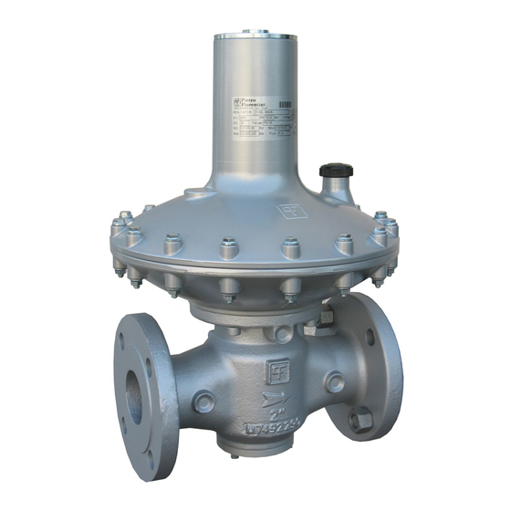
- Page 1 MT-185-E ENGLISH PRESSURE REGULATOR TECHNICAL MANUAL INSTALLATION ,COMMISSIONING AND MAINTENANCE ISTRUCTIONS...
- Page 2 Tecnical Manual MT 185-E TR. Head 3 Way body 4 Way body. INLET PRESSURE OUTLET PRESSURE...
- Page 3 Pressure regulator Dival 600 is classified as pressure accessory according to directive 97/23/EC (PED). The pressure regulator Dival 600 with embedded block device, with The handling of the apparatus and of its components must only be pressure switch for tripping in case of maximum pressure, is defined as...
-
Page 4: Table Of Contents
Tecnical Manual MT 185-E - INDEX -. INTRODUCTION START UP MAIN FEATURES GENERAL OPERATION OF THE PRESSURE REGULATOR DIVAL 600 4 GAS INPUT, CONTROL OF EXTERNAL TIGHTNESS SETTING SPRINGS AND SETTING COMMISSIONING THE REGULATOR COMMISSIONING THE REGULATOR WITH INCORPORATED LA/..SLAM-SHUT... - Page 5 The DIVAL 600 pressure regulator is a pressure regulator for previously cleaned gaseous fluids and is suitable for medium and low pressures. The DIVAL 600 is a normally open regulator and consequently opens in the event of: - Breakage of the main diaphragm;...
-
Page 6: Setting Springs
Tecnical Manual MT 185-E fig. 2a fig. 2b Tab. 1 SETTING SPRING Table 1 shows the calibration fields of the different foreseen springs. Springs Characteristics Dival 600 Code Colour Setting range (mbar) HEAD 2701345 YELLOW 10 ÷ 18 2700525 *... -
Page 7: General
- The piping upstream has been cleaned to expel residual impurities such as welding scale, sand, paint residues, water, etc. The usually foreseen arrangement is the one indicated in figure 3. Tab. 2a: Overall dimensions in mm Tipo Dival 600 1” Rp 1/2” Rp 1/4” Dival 600 1”1/2... - Page 8 Tecnical Manual MT 185-E OTHER POSSIBILITIES INSTALLATION AT RIGHT ANGLES Bleed cock Regulator Sensing line Contol pressure gauge On/off valve fig. 4 fig. 6 CONNECTING THE DEVICES The connections between the apparatus and the main piping must be Tab.3: Detail of multiple take-off made using stainless steel or cooper pipe with minimum internal diameter of 8 mm.
-
Page 9: La/.. Incorporated Slam-Shut
FOR INSTALLATION In the case of a service regulator of the ON-OFF type (stopping or starting of burners), you should remember that though the DIVAL 600 fig. 8 apparatus is classified as being of the fast reaction type, it requires an... - Page 10 Tecnical Manual MT 185-E Detail of manual button operated actuating device N.B.: L’O-ring is used for specific version. fig. 9 The slam-shut valve LA/.. consists essentially of an obturator (fig. 9) On the other hand, intervention as a result of a pressure decrease fitted on a stem, a releasing lever system, a control head and a manual occurs as follows: as long as the pressure Pd stays above the load of resetting system.
-
Page 11: La/.. Slam-Shut Setting Springs
Tecnical Manual MT 185-E Tab. 5 LA/… SLAM-SHUT SETTING SPRINGS Spring characteristics SLAM-SHUT LA/BP Code Colour SETTING RANGE in mbar Intervention for max. pressure 64470112 RO 30 ÷ 50 64470115GR GREY 50 ÷ 180 Intervention for min. pressure 64470024BI WHITE 6 ÷... - Page 12 Pressure Regulator Dival 600 can have an integrated silencer both in the normal the downstream pressure to reach the point set for monitor version and in the version having block valve or on-line monitor.
-
Page 13: Relief Valve
Tecnical Manual MT 185-E 4.1.1 DIRECT INSTALLATION IN THE LINE ACCESSORIES (fig. 14). When the relief valves fitted directly in the line that is, without the RELIEF VALVE interposition of an on/off valve, we recommend proceeding as follows: The relief valve is a safety device which releases a certain quality of Ensure that the downstream on/off valve V2 and the bled cock gas to the exterior when the pressure at the control point exceeds the 6 are closed;... -
Page 14: Start Up
Tecnical Manual MT 185-E GAS INPUT, CONTROL OF EXTERNAL START UP TIGHTNESS AND SETTING GENERAL The pressurization of the equipment shall be performed very slowly. Should not any stabilization procedure be carried out, it is After installation, check that the inlet/outlet on/off valves, any by-pass recommended to keep gas speed in the feeding piping at a value equal and the bleed cock are closet. - Page 15 Tecnical Manual MT 185-E very slowly open the downstream on /off valve V2, until the line is completely filled. Rest position (A and B communication) COMMISSIONING REGULATOR WITH INCORPORED LA/.. SLAM-SHUT Chamber with Controll position controlled (A and C communication) pressure If there is also a relief valve in the line, refer to par.
- Page 16 Setting of on-line apparatuses consisting of operation. Check intervention for pressure reduction by slowly Tab. 6 regulators Dival 600 + Slam-shut + Relief reducing the auxiliary pressure. If necessary, increase the valves intervention values for pressure increase or decrease by...
-
Page 17: Trouble-Shooting
Tecnical Manual MT 185-E Settino of on-line apparatuses consisting of regulator Dival 600 + Monitor + Slam-shut + Tab. 7 Relief valve Regulator set-point SLAM SHUT SLAM-SHUT MONITOR RELIEF VALVE (Pds) mbar Slam-shut not 10<Pds≤15 available Pds x 1.7 Pds x 2 15<Pds≤19... - Page 18 Tecnical Manual MT 185-E Tab. 9 SLAM-SHUTH (fig. 27) PROBLEM POSSIBLE CAUSES REMEDY Slam-shut obturator does not Control head diaphragm [16] Change the diaphragm close ruptured Obturator gasket [10] deteriorated Change the gasket Leakage from O-ring [66] worn Change slam-shut obturator Obturator seat [7] eroded or pitted Change the seat Wrong setting of max and/or...
-
Page 19: Maintenance
DISASSEMBLING AND RE-ASSEMBLY spots in the pictures 22, 23, 24, 25, 26 and 27. N.B. Pietro Fiorentini S.p.A. is in no case responsible, in case of use of DIVAL 600 REGULATOR non-original replacements. - Page 20 Tecnical Manual MT 185-E Completely unscrew the tap (354) and the internal regulating Completely unscrew the screw-nut (332) and take the spring out clamp (352). Then take out the spring (341); (331); Take the membrane-group out (320) Remove the screws (47) that fix the low support cap (310) with the high support cap(340);...
- Page 21 Tecnical Manual MT 185-E Take the screws out(46); Unscrew the screw (212) from the obturator (211) and separate alll the components of the balancing group (200); Separate the head (300) and the balancing group (200) from the regulator’s body (1); Unscrew the valve seat from the body (2), paying attention not to damage the sustain rims;...
-
Page 22: Replacement The Anti-Pumping Valve
Tecnical Manual MT 185-E To re-install the regulator you can carry out the operations described Place and insert the new anti-pumping valve in the cap seat with for the dismantling, in the opposite way. the two holes, present on one side of the anti-pumping valve, Before re-installing the sustain elements (o-rings, membranes, etc…), headed outwards;... - Page 23 Tecnical Manual MT 185-E INTERNAL RELIEF VERSION SILENCED VERSION fig. 22...
- Page 24 Tecnical Manual MT 185-E Gruppo 300 fig. 23 Standard head fig. 24 TR Head...
- Page 25 Tecnical Manual MT 185-E Unit 200 fig. 25b fig. 25a (Standard version DN 40 e 50) (Standard version DN 25 e 32) fig. 26b fig. 26a (Monitor version DN 40 e 50) (Monitor version DN 25 e 32)
- Page 26 Tecnical Manual MT 185-E LA/:: SLAM SHUTH VALVE (fig. 27) From the upper part, extract the shaft assembly consisting of the parts 9, 66, 19, 4 and 8, the bushes (22) and (23) and (19), and the shaft (5). Then, unscrew the shaft (5) and the obturator support (4), and remove the spring ring (9) to disassemble the Make sure that the slam-shut valve is in closed position;...
-
Page 27: Final Operation
Tecnical Manual MT 185-E START UP FINAL OPERATION Very slowly open the downstream on/off valve and, if necessary, CHECKING THE TIGHTNESSES ad just the regulator set-point by means of the internal adjustment ring (352). Very slowly open the on/off valve upstream from the regulator Set the tap (354) for normal control head or the blocking screw and using a foam solution or the like check: nut (358) for reduced control head. - Page 28 Tecnical Manual MT 185-E Tab. 10 MAINTENANCE WRENCHES FOR DIVAL 600 (+LA…) PRESSURE REGULATORS Combination Adiustable Compass pin spanner spanner wrench Ch. 8-9-10-11-12-13- Ch. 8-9-10-11-12-13- 14-15-16-17-18-19-20- L. 30 14-15-16-17-18-19-20- 21-22-23-24-25-26-27- 24-26-27-36-46 Hexagon or Flat head Philips screwdriver allen Key screwdriver Es.Ch PH 0 x 100 -...
Need help?
Do you have a question about the Dival 600 and is the answer not in the manual?
Questions and answers