
Related Manuals for PIETRO FIORENTINI NORVAL


Summary of Contents for PIETRO FIORENTINI NORVAL
- Page 1 PRESSURE REGULATOR NORVAL TECHNICAL MANUAL MT044 INSTALLATION, COMMISSIONING AND MAINTENANCE INSTRUCTIONS...
- Page 2 TECHNICAL MANUAL MT044 NORVAL Inlet pressure. Outlet pressure. Issue February 2003...
- Page 3 TECHNICAL MANUAL MT044 DECLARATION OF CONFORMITY The PIETRO FIORENTINI SPA with registered office in Milan (Italy) – via Rosellini, 1, declares under its sole responsibility that the apparatus series Norval bearing the CE marking showed in this manual are designed, manufactured, tested and inspected in accordance with the provisions of Pressure Equipment Directive 97/23/EC (PED).
- Page 5 TECHNICAL MANUAL MT044 PRECAUTIONS GENERAL PRECAUTIONS - The apparatus described in this manual is a device subject to pressure installed in systems under pressure; - the apparatus in question is normally installed in systems for transporting flammable gases (natural gas, for example). PRECAUTIONS FOR THE OPERATORS Before proceeding with installation, commissioning or maintenance, operators must: - examine the safety provisions applicable to the installation in which they must work;...
- Page 6 CONFORMITY TO DIRECTIVE 97/23/EC (PED) Pressure regulator Norval is classified as fail open regulator according to the standard EN 334 therefore it is categorized as pressure accessory according to directive 97/23/EC (PED). The safety device in-line monitor is categorized as safety accessory according PED. The regulator Norval when incorporating slam shut valve with pressure switche for overpressure is categorized as safety accessory according to PED, therefore it can be used both as pressure accessory and safety accessory to PED.
-
Page 7: Table Of Contents
MAINTENANCE PROCEDURE FOR THE NORVAL REGULATOR + I-N + ER ......43... -
Page 9: Introduction
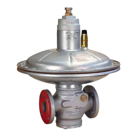
It is also appropriate to provide a brief illustration of the main features of the regulator and of its accessories. MAIN FEATURES The NORVAL pressure regulator is a pressure regulator for previously cleaned gaseous fluids and is suitable for medium and low pressures. - Page 10 TECHNICAL MANUAL MT044 Fig. 1...
-
Page 11: Regulator Setting Springs
TECHNICAL MANUAL MT044 TAB. 1 Standard Regulator Setting Springs (Fig. 2) Springs characteristics SETTING RANGE in mbar Covers Ø 630 Ø 495 Ø 375 Ø 375 TR CodE Colour De Lo 2” - 3” 4” 1” ÷ 2” 2” ÷ 4” 1” ÷ 2” 2” ÷... -
Page 12: Regulator Setting Springs
TECHNICAL MANUAL MT044 1.3.1 TAB. 2 Upturned Regulator Setting Springs (Fig. 3) Springs characteristics SETTING RANGE in mbar Covers Ø 630 Ø 495 Ø 375 Ø 375 TR Code Colour De Lo 2” - 3” 4” 1” ÷ 2” 2” ÷... -
Page 13: Installation
TECHNICAL MANUAL MT044 INSTALLATION GENERAL Pressure regulator does not require any supplementary upstream safety accessory for protection against overpressure compared with its design pressure PS, when upstream reducing station is sized for a max downstream incidental pressure MIPd ≤ 1,1 PS. Before installing the regulator it is necessary to ensure that: - the regulator can be inserted in the space provided and that subsequent maintenance operations will be sufficiently practicable;... - Page 14 TECHNICAL MANUAL MT044 INSTALLATION AT RIGHT ANGLES Regulator Bleed cock Sensing line Control pressure gauge On/Off valve TAB. 4 DETAIL OF MULTIPLE TAKE-OFF...
- Page 15 In the case of a service regulator of the ON-OFF type (stopping or starting of burners), you should remember that though the NORVAL apparatus is classified as being of the fast reaction type, it requires an appropriately dimensioned volume of gas between the apparatus itself and the burner so as to partly absorb the pressure swings...
-
Page 16: Accessories
TECHNICAL MANUAL MT044 ACCESSORIES RELIEF VALVE The relief valve is a safety device which releases a certain quantity of gas to the exterior when the pressure at the control point exceeds the set-point as a result of short-lasting events such as, for example, the very fast closing of the on/off valves and/or overheating of the gas with zero flow rate demand. -
Page 17: Direct Installation In The Line
TECHNICAL MANUAL MT044 3.1.1 DIRECT INSTALLATION IN THE LINE (Fig. 5) When the relief valve is fitted directly in the line that is, without the interposition of an on/off valve, we recommend proceeding as follows: 1) ensure that the downstream on/off valve V2 and the bleed cock 6 are closed; 2) increase the pressure in the downstream section to the value at which intervention should occur by connecting a controlled auxiliary pressure to the cock 6 and stabilise it at the desired value;... -
Page 18: Modularity
TECHNICAL MANUAL MT044 MODULARITY The modular-type conception of NORVAL series regulators means that it is also possible to fit the slam-shut incorporated with the body itself even after the installation of the regulator. Furthermore, the regulator can be adapted for operation as an in-line monitor by installing a special device. - Page 19 TECHNICAL MANUAL MT044 The slam-shut mechanism consists of: • a mobile obturator A with sealing gaskets subject to the load of the closing spring G; • a lever assembly L whose rotation causes the movement of the obturator A; • a pressure switch device I-N whose internal motion determines the open or closed position of the obturator A. Fig.
-
Page 20: Slam-Shut Setting Springs
TECHNICAL MANUAL MT044 TAB. 6 SLAM-SHUT SETTING SPRINGS SETTING RANGE mbar Springs characteristics I-N (Fig. 9) I-N (Fig. 10) I-N/TR (Fig. 9 and fig. 10) Code Colour 2700565 WHITE 5.25 7.25 13 ÷ 33 17 ÷ 35 2700675 YELLOW 5.25 7.25 25 ÷... -
Page 21: Norval Functioning As A Monitor
• Can also be mounted on a normal regulator already installed. 4.3.2 NORVAL OPERATION WITH MONITOR FUNCTIONS The NORVAL (fig.11) with monitor functions is a regulator which, compared with the normal version, has a further mobile assembly balancing device which guarantees greater... -
Page 22: Start Up
TECHNICAL MANUAL MT044 START UP GENERAL After installation, check that the inlet/outlet on/off valves, any by-pass and the bleed cock are closed. Before commissioning, you must ensure that the conditions of use comply with the characteristics of the apparatuses. These characteristics are recalled by the symbols on the specification plates applied to each apparatus. We recommend actuating the opening and closing valves very slowly. - Page 23 TECHNICAL MANUAL MT044 The list of symbols used and their meanings are listed below: = Conformity to PED Directive Pemax= maximum operating pressure at the inlet of the apparatus bpe= range of variability of the inlet pressure of the pressure regulator in normal operating conditions PS= massima pressione che può...
-
Page 24: Gas Input, Control Of External Tightness And Setting
TECHNICAL MANUAL MT044 GAS INPUT, CONTROL OF EXTERNAL TIGHTNESS AND SETTING The apparatus pressurization operation must be carried out very slowly. To protect the apparatus from damage, the following operations must never be carried out: - Pressurization through a valve located downstream from the apparatus itself. - Depressurization through a valve located upstream from the apparatus itself. -
Page 25: Commissioning The Regulator With Incorporated I-N Slam-Shut
TECHNICAL MANUAL MT044 COMMISSIONING THE REGULATOR WITH INCORPORATED I-N SLAM-SHUT If there is also a relief valve in the line, refer to par. 3.1 to check it. Fig. 13 Check and adjust the intervention of the slam-shut 7 as follows: A) For slam-shuts connected to the downstream piping by a three-ways deviator push valve 11, proceed as follows (Fig. - Page 26 TECHNICAL MANUAL MT044 Rest position (A and B in communication) Safety device Chamber with Controll position (A and C in communication) controlled pressure Environment with the pressure to keep under control Fig. 14 B) On devices without the "push" valve (fig. 15) we recommend connecting the control head separately to a controlled auxiliary pressure and repeating the operations described above.
- Page 27 TECHNICAL MANUAL MT044 ATTENTION At the end of the operation, reconnect the control head to the downstream pressure take-off. N.B.: The intervention tests should be repeated at least every 6 months. At the end of the slam-shut check, proceed as follows: 1) check that the slam-shut is in the closed position;...
- Page 28 TECHNICAL MANUAL MT044 Settings of in-line apparatuses consisting of Regulator TAB. 7: + Slam-shut + Relief valve Regulator set-point Set-point Set-point Set-point (Pas) mbar RELIEF VALVE SLAM-SHUT Max SLAM-SHUT Min 20 mbar 8<Pas≤12 Slam-shut not 25 mbar available 12<Pas≤15 10 mbar Pas x 1.5 15<Pas≤19 Pas + 20 mbar...
-
Page 29: Commissioning The Regulator Plus Norval In-Line Monitor With Incorporated I-N Slam-Shut Valve
TECHNICAL MANUAL MT044 COMMISSIONING THE REGULATOR PLUS NORVAL IN-LINE MONITOR WITH INCORPORATED I-N SLAM-SHUT VALVE If there is also a relief valve in the line, refer to par. 3.1 to check it. Fig. 16 Check and adjust the intervention of the slam-shut 7 as follows: A) For slam-shuts connected to the downstream piping by a three-ways deviator push valve 11, proceed as follows (Fig. - Page 30 TECHNICAL MANUAL MT044 B) On devices without the "push" valve (fig. 15) we recommend connecting the control head separately to a controlled auxiliary pressure and repeat the operations described above. ATTENTION At the end of the operation, reconnect the control head to the downstream pressure take-off. N.B.: The intervention tests should be repeated at least every 6 months.
- Page 31 TECHNICAL MANUAL MT044 Settings of in-line apparatuses consisting of Regulator TAB. 8: + Monitor + Slam-shut + Relief valve Regulator set-point Set-point Set-point Set-point Set-point (Pas) mbar RELIEF VALVE SLAM-SHUT Max SLAM-SHUT Min MONITOR 8<Pas≤12 Slam-shut not 25 mbar 30 mbar available 12<Pas≤15 10 mbar...
-
Page 32: Trouble-Shooting
TECHNICAL MANUAL MT044 TROUBLE-SHOOTING The problems of various kinds which could arise over time are highlighted below. They derive from phenomena associated with the conditions of the gas as well, of course, as with the natural ageing and wear of the materials. It must be remembered that all operations on the apparatuses must be carried out by highly qualified personnel with appropriate knowledge of the subject. - Page 33 TECHNICAL MANUAL MT044 TAB. 9 REGULATOR (FIG. 17) PROBLEM POSSIBLE CAUSES REMEDY Dirt on the reinforced gasket [4] Clean O-ring [60] worn Replace No tightness at Q=0 O-ring [60] worn Replace Compensating diaphragm [29] ruptured Replace Compensating diaphragm [29] improperly fixed Reinforced gasket [4] damaged Replace Shaft locked by incrustation during...
-
Page 34: Regulator Slam-Shut
TECHNICAL MANUAL MT044 TAB. 10 REGULATOR SLAM-SHUT (FIG. 18) PROBLEM POSSIBLE CAUSES REMEDY Slam-shut obturator does not close Control diaphragm [16] ruptured Change the diaphragm Obturator gasket [10] deteriorated Change the gasket Leakage from slam-shut obturator O-ring [66] worn Change Obturator seat [7] eroded or pitted Change the seat Wrong setting of maximum and/or... -
Page 35: Maintenance
TECHNICAL MANUAL MT044 MAINTENANCE GENERAL Periodical inspection and maintenance shall be carried out according to the regulations in force (kind and frequencies). Before carrying out any operation it is important to ascertain that the regulator has been cut off both upstream the regulator and the on/off valves. -
Page 36: Norval Regulator Maintenance Procedure
TECHNICAL MANUAL MT044 NORVAL REGULATOR MAINTENANCE PROCEDURE Fig. 17... - Page 37 TECHNICAL MANUAL MT044 Procedure for the disassembly, complete replacement of the spare parts and re-assembly of the NORVAL pressure regulator (PROGRAMMED PREVENTIVE MAINTENANCE) PRELIMINARY OPERATIONS A. Render the regulator safe; B. Ensure that the pressure upstream and downstream from it is 0.
- Page 38 TECHNICAL MANUAL MT044 RE-ASSEMBLY Remembering that the O-rings and the sliding parts (rods, etc.) must be lightly lubricated with a fine layer of silicone grease before re-assembly, while static parts require grease to render them softer but, especially, to hold them in their slots: 22) Fit back the intermediate flange, pos.
-
Page 39: Norval Regulator + I-N Maintenance Procedure
TECHNICAL MANUAL MT044 NORVAL REGULATOR + I-N MAINTENANCE PROCEDURE Fig. 18... - Page 40 TECHNICAL MANUAL MT044 Procedure for the disassembly, complete replacement of the spare parts and re-assembly of the NORVAL pressure regulator + I-N (PROGRAMMED PREVENTIVE MAINTENANCE) PRELIMINARY OPERATIONS Render the regulator safe; Ensure that the pressure upstream and downstream from it is 0.
- Page 41 TECHNICAL MANUAL MT044 23) Slacken the fixing screws, pos. , of the slam-shut cover, pos. 24) Remove the slam-shut cover, pos. 25) Remove the retaining ring, pos. , which fixes the reset lever, pos. 26) Remove the reset lever, pos. 27) Remove the retaining ring, pos.
- Page 42 TECHNICAL MANUAL MT044 52) Check once again that the holes in the diaphragm and bottom cover line up properly. 53) Put the top cover back into its original position with the anti-pumping valve towards the downstream side. 54) Put back and fix the screws, pos. , with a torque of 5 KG.M.
-
Page 43: Maintenance Procedure For The Norval Regulator + I-N + Er
TECHNICAL MANUAL MT044 MAINTENANCE PROCEDURE FOR THE NORVAL REGULATOR + I-N + ER Fig. 19... - Page 44 TECHNICAL MANUAL MT044 Procedure for the disassembly, complete replacement of the spare parts and re-assembly of the NORVAL pressure regulator + I-N + ER (PROGRAMMED PREVENTIVE MAINTENANCE) PRELIMINARY OPERATIONS A. Render the regulator safe; B. Ensure that the pressure upstream and downstream from it is 0.
- Page 45 TECHNICAL MANUAL MT044 22) Remove the obturator support of the slam-shut valve, pos. , along with the spring, pos. , and the obturator, pos. 23) Check and clean the inside of the regulator body. 24) Carefully check that the valve seat, pos. , is in a good state, both with regard to the regulator seat and the slam-shut seat.
- Page 46 TECHNICAL MANUAL MT044 51) Keeping the rod, pos. , fixed, fully tighten the self-locking nut, pos. 52) Proceeding slowly, carry out vertical movements of the top of the rod to check that it moves properly. 53) Reassemble the gasket, pos. , the diaphragm, pos.
-
Page 47: Final Operations
TECHNICAL MANUAL MT044 FINAL OPERATIONS CHECKING THE TIGHTNESSES AND SETTING Very slowly open the on/off valve upstream from the regulator and using a foam solution or the like check: • the tightness of the external surfaces of the regulator; • the tightness of the slam-shut; •... - Page 48 TECHNICAL MANUAL MT044 TAB. 11 MAINTENANCE WRENCHES FOR NORVAL PRESSURE REGULATORS (+I-N) (+ER) Combination spanner Adjustable spanner Compass pin wrench Box spanner Hexagon or allen key Hexagonal T key Hexagonal socket T wrench Phillips screwdriver Flat head screwdriver O-Ring extraction tool...
- Page 49 TECHNICAL MANUAL MT044 WEIGHT OF THE COMPONENTS TAB. 12 WEIGHT OF THE COMPONENTS IN KG. 1” 1” 2” 2” 3” 4” 6” 8” 1“ ” 10,3 10,3 10,3 17,3 17,3 17,3 10,8 10,8 10,8 16,3 16,3 16,3 12,5 22,5 14,5 14,5 16,6 25,5...
-
Page 50: List Of Recommended Spares
TECHNICAL MANUAL MT044 LIST OF RECOMMENDED SPARE PARTS... - Page 51 TECHNICAL MANUAL MT044 NORVAL pression regulator...
- Page 52 TECHNICAL MANUAL MT044 VERSIONS DN: 4” DN: 4” Fig. E Fig. F DN: 4” ÷ 3” DN: 1”÷ 3” Fig. B Fig. C REDUCED HEAD (TR) ONLY COVERS Ø 375 OR Ø 375 TR DN: 4”- 6”- 8” Fig. D...
- Page 53 TECHNICAL MANUAL MT044 N. OF PIECES 1” ÷ 3” 1” ÷ 3” TR Only Only 4” - 6” - 8” 2” -3” 4” TR POS. DESCRIPTION ø 375 TR Reinforced gasket Guide ring Diaphragm Gasket Diaphragm U-ring O. Ring O. Ring O.
- Page 54 TECHNICAL MANUAL MT044 ...+ I-N,...I-N/TR SLAM-SHUT DN: 1” ÷ 3” Fig. G DN: 4” - 6” - 8” Fig. H RESET LEVER RESET LEVER DN: 1” ÷ 3” DN: 4” - 6” - 8” Fig. K Fig. L...
- Page 55 TECHNICAL MANUAL MT044 SLAM-SHUT CONTROL DEVICE Versions DVGW ...I-N/TR Reduced head Fig. N N. OF PIECES Fig. M POS. DESCRIPTION 1” ÷ 3” 4” - 6” - 8” Obturador U-ring Guide ring O. Ring O. Ring Guide ring O. Ring O.
- Page 56 TECHNICAL MANUAL MT044 ...+ MONITOR ER DN: 1” ÷ 3” Fig. P DN: 6” ÷ 8” Fig. R DN: 4” Fig. Q N. OF PIECES 1” ÷ 3” 4” 6” + 8” POS. DESCRIPTION Diaphragm O. Ring O. Ring O. Ring O.
- Page 57 TECHNICAL MANUAL MT044 WHEN ORDERING SPARE PARTS, PLEASE SPECIFY: Type of regulator Dne (nominal input diameter) Pe (inlet pressure) Pa (outlet pressure) Works no. (Serial no.) Year of manufacture Type of fluid used Regulator cover diameter Gasket hardness (55 or 85 ShA) Type of head for slam-shut (I-N, I-N/TR) (if installed) Monitor (if installed) The no.
- Page 58 TECHNICAL MANUAL MT044 NOTES...
- Page 59 TECHNICAL MANUAL MT044 Ordering Information: Part No. PFN375DN50-40, PFN375DN50-45...
Need help?
Do you have a question about the NORVAL and is the answer not in the manual?
Questions and answers