
Related Manuals for Carlisle Ransburg A14895 Series


Summary of Contents for Carlisle Ransburg A14895 Series
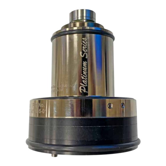
- Page 1 SERVICE INSTRUCTION Robot High Speed Turbine Inspection and Rebuild Procedure Model: A14895-XX Silver Shaft Style SI-21-06-R1 (11/2021) 1 / 32 www.carlisleft.com...
-
Page 2: Table Of Contents
CONTENTS CONTENTS SAFETY: Safety Precautions ................................3 Hazards / Safeguards ..............................4 EQUIPMENT AND MATERIALS REQUIRED: Equipment / Materials ..............................8 OPERATION: 9-28 Important Numbers ................................9 Tear Down Procedures & Visual Inspection of Parts ....................10 Optional Alignment Tool Method ..........................27 PARTS IDENTIFICATION: 29-31 Spindle Replacement ..............................29 Tool Options... -
Page 3: Safety
This information relates to USER SAFETY and PREVENTING and safety literature for your equipment, contact your local EQUIPMENT PROBLEMS. To help you recognize this Carlisle Fluid Technologies representative or Carlisle Fluid information, we use the following symbols. Please pay Technologies technical support. -
Page 4: Hazards / Safeguards
SAFETY Return To Contents AREA SAFEGUARDS HAZARD Tells where hazards Tells how to avoid the hazard. Tells what the hazard is. may occur. Fire Hazard Spray Area Fire extinguishing equipment must be present in the Improper or inadequate spray area and tested periodically. operation and maintenance procedures will cause a fire Spray areas must be kept clean to prevent the... - Page 5 SAFETY Return To Contents AREA SAFEGUARDS HAZARD Tells where hazards Tells how to avoid the hazard. Tells what the hazard is. may occur. Explosion Hazard Spray Area Improper or inadequate Electrostatic arcing must be prevented. Safe sparking operation and maintenance distance must be maintained between the parts being procedures will cause a coated and the applicator.
- Page 6 SAFETY Return To Contents AREA SAFEGUARDS HAZARD Tells where hazards Tells how to avoid the hazard. Tells what the hazard is. may occur. Spray Area / Electrical Discharge High Voltage There is a high voltage device Parts being sprayed and operators in the spray Equipment that can induce an electrical area must be properly grounded.
- Page 7 SAFETY Return To Contents AREA SAFEGUARDS HAZARD Tells where hazards Tells how to avoid the hazard. Tells what the hazard is. may occur. Electrical Electrical Discharge Unless specifically approved for use in hazardous Equipment locations, the power supply, control cabinet, and all High voltage equipment is utilized in the process.
-
Page 8: Equipment And Materials Required
EQUIPMENT AND MATERIALS REQUIRED Return To Contents EQUIPMENT AND MATERIALS REQUIRED 1. 2/0 or finer abrasive paper or cloth 1-inch-wide x 8-8 NOTE 1/2-inch-long strips (25mm wide x 200mm long) (in- cluded with kit A14896-00 and A12951-02) Circu- lar Donut 2/0 or finer abrasive disks .950 I.D. x 1.54 †... -
Page 9: Operation
OPERATION Return To Contents OPERATION IMPORTANT NUMBERS REBUILD KIT NUMBER USE SERVICE KIT A14896-00 PART NUMBER AND SERIAL NUMBER LOCATION www.carlisleft.com 9 / 32 SI-21-06-R1 (11/2021) -
Page 10: Tear Down Procedures & Visual Inspection Of Parts
OPERATION Return To Contents TEAR DOWN PROCEDURES & VISUAL INSPECTION OF PARTS Step 1 Remove the rear cover screws with a T10 Star wrench from rear of the turbine motor and set aside. CRITICAL AREAS THAT MUST BE DAMAGE FREE SEE FIGURE 1-2 FOR NON-REPAIRABLE CONDITION... - Page 11 OPERATION Return To Contents Step 3 Next, remove shaft rotor assembly from the turbine housing. Examine the shaft’s outside diameter for contact marks. (See Figure 1-3 New Shaft Condition) Typically contact marks can be found at the bottom of the shaft and at the top. The contact marks consist of a bronze material from the air bearings transferring onto the outside diameter of the shaft.
- Page 12 OPERATION Return To Contents Step 4 INSPECT SHAFT “INSIDE DIAMETER” Visually inspect the inside diameter of shaft for paint in the threads and the undercut area. It will need to be cleaned up accordingly. See Figure 1-4 - If circular wear marks are identified on the shafts taper it will need to be inspected to verify if taper is still good as shown in Figure 1-4A.
- Page 13 OPERATION Return To Contents Step 5 Pull off spacer plate from turbine assembly and set aside until later. Bearing Air O-Ring, retain do not lose. “DO NOT REMOVE” FRONT THRUST BEARING - IT IS PRESET BY THE SUPPLIER. IT IS NOT FIELD REPLACEABLE Figure: 1-5 VISUAL APPEARANCE OF NEW Step 6...
- Page 14 OPERATION Return To Contents Step 7 Removal of Dual Bearings from Bearing Housing (Set Screw Extraction) Set Screw Removal: Remove the two setscrews using 3mm hex wrench as shown in Figure 1-7. Figure 1-7 O-RINGS SPRING Step 8 Take note of the setscrew assembly: There should be (2) O-Rings and small spring that are removed from the two bear- ings.
- Page 15 OPERATION Return To Contents Step 9 Removal of Dual Bearings from Bearing Housing (Bearing Removal) Dual Bearing Removal: Use only non-metallic tool to extract bearing from housing. Bearings will remove with the slight pull of the forefinger as shown in Figure 1-9.
- Page 16 OPERATION Return To Contents Step 10 (Cont.) Dual Bearing Inspection & Repair Process Extract O-rings from bearing as shown in Figure 1-10A. Figure 1-10A Step 11 The radial bearings may be soaked in a solvent compatible with the paint debris intrusion. Use of an Ultrasonic cleaner may aid in loosening of the foreign material.
- Page 17 OPERATION Return To Contents Step 13 Clean Air Bearing Jets After Polishing Operation: Using an approved compressed solvent with exten- sion tube and face shield. Spray solvent through each air bearing jet to make sure they are clean and free of debris. Plugged holes will result in pre- mature turbine motor failure.
- Page 18 OPERATION Return To Contents Step 14 (Cont.) NOTE † After polishing is complete, the minimum shaft diameter allowed is .8828 (Inches) / 22.42mm. Measure the entire shaft length with micrometers. If the diameter is under the measurement stated .8828 Inches / 22.42mm discard shaft return bear- ing housing assembly and rear cover for core cred- it towards an exchange rebuild unit.
- Page 19 OPERATION Return To Contents Step 16 (Cont.) ing the rear thrust bearing final inspection with the .004 inch (0.102mm) wire will be required to assure jets are open and clean. Figure 1-16 Optional Tool A13270-00 Thrust plate sanding tool can be purchased and used to polish the thrust plate on both sides of the shaft using the 2/0 abrasive sanding paper/ cloth disc as shown in Figure 1-16A.
- Page 20 OPERATION Return To Contents Step 16 (Cont.) Clean Shaft: After polishing shaft thrust faces clean entire shaft with aerosol electronic contact cleaner, wear googles, wipe down shaft with a lint free cloth. Figure 1-16B Step 17 Inspect Bearing Air Jets in both thrust faces as shown in Figure 1-17 Inspect Bearing Air Jets:...
- Page 21 OPERATION Return To Contents Step 18 USE SAFETY GLASSES DURING THIS PROCEDURE Flush Bearing Air Jets with an aerosol electronic contact cleaner as shown in Figure 1-18 Solvent Flush Ports: Apply aerosol feed tube to bearing air port as shown. The hole on the opposite side need to be blocked.
- Page 22 OPERATION Return To Contents Step 19 Install O-Rings: Locate O-rings from replacement kit and install onto bearing as shown in Figure 1-19. Please note new bearings may NOTE need to be installed if required. New bearings are included with the rebuild kits. (A12951-01) †...
- Page 23 OPERATION Return To Contents Step 21 Lightly lubricate bearing housing Use Ransburg lubricant A11545 sparingly enough (super thin film) to allow bearings to slide into position. Too much lubricant could lead to air bearing failure. Figure 1-21A Figure 1-21B Step 22 Slide Bearings into Position within the Housing Slide Bearings into Housing:...
- Page 24 OPERATION Return To Contents Step 23 Install Set Screws into Bearings Install New O-rings and spring: Install new O-rings and spring onto set screws as shown in Figure 1-23A. Figure 1-23A Apply a drop of light duty thread retaining compound to first thread (7969-05) Install Assembled Set Screws into bearing housing: Visually inspect to make sure blind holes in...
- Page 25 OPERATION Return To Contents Step 25 Locate Spacer and Shaft Important Assembly Note: Inspect spacer and shaft to make sure, that they have corresponding serial numbers. They are a matched set. If numbers do not match locate ones that do match. Failure to do so will result in turbine motor failure.
- Page 26 OPERATION Return To Contents Alignment Hole Alignment Pin Bearing Air O-Ring Step 28 Assemble Rear Cover onto Bearing Housing Assemble Rear Cover: Observe alignment pin during assembly. Make sure bearing air O-ring is in place. Assemble rear cover. Figure 1-28 Step 29 Assemble Rear Cover onto Bearing Housing...
-
Page 27: Optional Alignment Tool Method
OPERATION Return To Contents OPTIONAL ALIGNMENT TOOL METHOD Step 29A Assemble Rear Cover onto Bearing Housing Assemble Star Head Screws: Replace star screws into rear cover of turbine motor. Do not tighten leave loose and proceed to next step. Figure 1-29A Step 30A Align housing, Spacer and Rear Cover in Alignment Ring... - Page 28 OPERATION Return To Contents Step 31 Install New O-Rings onto Turbine Motor Install New O-Rings onto turbine motor as shown in Figures Figure 1-31A 1-31A and 31B Figure 1-31B SI-21-06-R1 (11/2021) 28 / 32 www.carlisleft.com...
-
Page 29: Parts Identification
PARTS IDENTIFICATION Return To Contents PARTS IDENTIFICATION Spindle Replacement www.carlisleft.com 29 / 32 SI-21-06-R1 (11/2021) - Page 30 PARTS IDENTIFICATION Return To Contents SPINDLE REPLACEMENT PARTS Item No. Part No. Description A12907-00 SCREW KIT (6 SCREWS) A12908-00 O-RING KIT (16 O-RINGS) (SEE KIT BREAKDOWN FOR EACH O-RING) A14901-00 SHAFT AND SPACER ASSEMBLY KIT A14902-00 REAR COVER ASSEMBLY WITH THRUST BEARING A14898-00 RADIAL BEARING A14899-00...
-
Page 31: Tool Options
PARTS IDENTIFICATION Return To Contents SERVICE KIT A14896-00 (CLEANING) Item No. Part No. Description RPM-63 SANDPAPER STRIP SSC-6001 LINT FREE TISSUE RPM-62-1 SANDPAPER DISC A13343-00 WIRE, 6 1/4” A12961-00 SPRING A12908-00 O-RING KIT A12907-00 KIT,SCREW SI-21-06 SERVICE INSTRUCTION (A14895-XX) TOOL OPTIONS ALIGNMENT TOOL (A13268-00) THRUST BEARING SANDING TOOL (A13270-00) BEARING TOOL (A13269-00) - Page 32 WARRANTY POLICY This product is covered by Carlisle Fluid Technologies’ materials and workmanship limited warranty. The use of any parts or accessories, from a source other than Carlisle Fluid Technologies, will void all warranties. Failure to reasonably follow any maintenance guidance provided, may invalidate any warranty.
Need help?
Do you have a question about the Ransburg A14895 Series and is the answer not in the manual?
Questions and answers