
Subscribe to Our Youtube Channel
Related Manuals for Carlisle Ransburg RPM-401-1


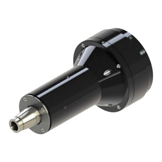
Summary of Contents for Carlisle Ransburg RPM-401-1
- Page 1 SERVICE MANUAL Turbine Inspection and Rebuild Procedures Model: RPM-401-1 RPM-401-2 SI-22-04-R1 (04/2023) 1 / 24 www.carlisleft.com...
-
Page 2: Table Of Contents
CONTENTS CONTENTS SAFETY: Safety Precautions ................................3 Hazards / Safeguards ..............................4 INTRODUCTION: Equipment and Materials Required ..........................8 MAINTENANCE: 9-20 Teardown Process of RPM-401-2 ..........................9 Visual Inspection and Cleaning of an Air Bearing ......................12 PARTS IDENTIFICATION: 21-22 Spindle Replacement ..............................21 Parts List ..................................22 Additional Service Kits RPM-401-1 and RPM-401-2 ....................23 SI-22-04-R1 (04/2023) 2 / 24... -
Page 3: Safety
This information relates to USER SAFETY and PREVENTING and safety literature for your equipment, contact your local EQUIPMENT PROBLEMS. To help you recognize this Carlisle Fluid Technologies representative or Carlisle Fluid information, we use the following symbols. Please pay Technologies technical support. -
Page 4: Hazards / Safeguards
SAFETY AREA SAFEGUARDS HAZARD Tells where hazards Tells how to avoid the hazard. Tells what the hazard is. may occur. Spray Area Fire Hazard Fire extinguishing equipment must be present in the Improper or inadequate operation spray area and tested periodically. and maintenance procedures will cause a fire hazard. - Page 5 SAFETY AREA SAFEGUARDS HAZARD Tells where hazards Tells how to avoid the hazard. Tells what the hazard is. may occur. Explosion Hazard Spray Area Improper or inadequate operation Electrostatic arcing must be prevented. Safe sparking and maintenance procedures will distance must be maintained between the parts being cause a coated and the applicator.
- Page 6 SAFETY AREA SAFEGUARDS HAZARD Tells where hazards Tells how to avoid the hazard. Tells what the hazard is. may occur. Electrical Discharge Spray Area / High Voltage Parts being sprayed and operators in the spray area must be There is a high voltage device Equipment properly grounded.
- Page 7 SAFETY AREA SAFEGUARDS HAZARD Tells where hazards Tells how to avoid the hazard. Tells what the hazard is. may occur. Electrical Electrical Discharge Equipment High voltage equipment is Unless specifically approved for use in hazardous locations, utilized in the process. Arcing the power supply, control cabinet, and all other electrical in the vicinity of flammable or equipment must be located outside or applicable country...
-
Page 8: Introduction
• Allen Wrench, 2.5mm (3/32 in.) and 1/16 in. (1.5mm) to assure proper fitment. This statement is only applicable • RPM-412 Wrench if using genuine Ransburg (Carlisle Fluid Technologies) support parts. 4. Use the following rebuild kit to service RPM-401-2, kit number KK-4461 or KK-4461-1. -
Page 9: Maintenance
MAINTENANCE MAINTENANCE TEARDOWN PROCESS Step 3: Inspection of Rotor Looking at RED circle, make sure the magnets are seated OF RPM-401-2 (STEPS 1-9) visually. Damaged magnet will result in speed control issues if using Ransburg speed controllers. Step 1: Serial Number Identification If seeking warranty and or evaluation, please provide serial number of turbine motor. - Page 10 MAINTENANCE Step 6: Remove Feed Plate and Rotor Step 4: Removal of Screws from Rotor You possibly will need to push on turbine shaft by hand Using Allen Wrench 3/32in (2.5mm) remove four screws from to free up feed plate assembly. Once feed plate is loose rotor as shown.
- Page 11 MAINTENANCE Observe O-ring A13065-00 placement in front of bearing as Typical view of the shaft assembly removed from the motor shown, see red arrow shown. Notice the o-ring (A13065-00) on the front bearing. Step 8: Remove Second Bearing and Spacer in Housing, See Following Views Pull front bearing out of housing along with RPM-51 spacer as shown.
-
Page 12: Visual Inspection And Cleaning Of An Air Bearing
MAINTENANCE Step 9: Remove Screws from Bearing and If the bearing is acceptable proceed “facing off” of the ma- Thrust Plate chined face. Use emery cloth 2/0 grade and a “flat surface” Before disassembly of air bearing from thrust plate make such as granite plate. - Page 13 MAINTENANCE Step 11: A14779-00 (RPM-25) Rear Bearing Step 12: RPM-26 Front Upper Bearing Inspect the “V” groove on the bottom of the thrust plate around Using a narrow strip of the emery cloth included in rebuild kit, the circumference of the bearing air holes. The groove must rub lightly on ID of the bearings both front and rear.
- Page 14 MAINTENANCE Now rinse the bearing air holes clean using the electrical Please note: if the electrical contact cleaner will not pass- contact cleaner with the small red tube attached. The spray through jet in strong defined stream use wire to open jet. must escape from the opposite side of the hole noting that If neither the wire nor electrical contact cleaner will pass the hole is clean of all debris.
- Page 15 MAINTENANCE Polish both flanges on the shaft, use the cut emery cloth Step 16: (RPM-27) Body Clean and Inspect donuts provided in the rebuild kit KK-4461 / KK-4461-1. Place Replace O-ring the donut onto the flange of the shaft rough side forward. Inspect the body for damage clean the body, if necessary, Place the flange bearing face onto donut.
- Page 16 MAINTENANCE Step 18: Front Cover (RPM-100) and (RPM-51) Step 17: (RPM-30) Feed Plate Clean and Inspect Bearing Spacer Clean and Inspect Replace O-rings The three O-rings on this feed plate from front to back are: • A13066-00 • A13064-00 • A13068-00 Inspect the feed plate for damage caused by the rotor.
- Page 17 MAINTENANCE RE-ASSEMBLY PROCESS OF RPM-401-2 (STEPS 20-27) Torque to 5-6 lbs.-in. (.56-.68 Nm) using Allen Wrench size 1/16 in. (1.5mm) the eight (8) Step 19: Re-Assembly Process of RPM-401-2 screws as shown. Turbine Motor NOTE † During re-assembly of turbine motor make sure your hands are clean and free of any grease or oil.
- Page 18 MAINTENANCE Step 22: Install RPM-100 Front Cover to Housing Step 24: Install Feed Plate RPM-30 onto Housing Assemble RPM-100 cover onto the RPM-27 body hand tight Verify O-ring A14791-00 is installed onto the back side of only. Cover is needed now to keep the bearing assembly the rear thrust bearing noted in step 23.
- Page 19 MAINTENANCE Step 25: Assemble Rotor onto Shaft Step 26: Assemble Rear Cover onto the housing Carefully slip the rotor onto the shaft, use Allen wrench size Verify the small O-ring is installed into the rear cover 3/32 in. (2.5 mm) if needed to rotate the rotor into position of counterbore for bearing the air connection.
- Page 20 MAINTENANCE Step 27: Front Cover Final Assembly (RPM-100) Tighten the SHCS M3x6mm screws to the RPM-100 front cover, torque to 15-16 lbs.-in (1.7-1.8 N-m) using Allen wrench size 3/32 in. (2.5 mm). 15-16 LBS.-IN (1.7-1.8 Nm) GENERAL NOTES: 1. Once turbine motor is assembled following the steps outlined throughout this manual the shaft should spin freely by hand touch and not be bound up.
-
Page 21: Parts Identification
PARTS IDENTIFICATION PARTS IDENTIFICATION Spindle Replacement ITEMS WITH AN ASTERISK “*” ARE ONLY AVAILABLE IN KIT 76909-00. ITEMS WITH TWO ASTERISKS “**” ARE ONLY AVAILABLE IN KIT A14775-00. www.carlisleft.com 21 / 24 SI-22-04-R1 (04/2023) - Page 22 PARTS IDENTIFICATION NOTE † All parts listed for RPM-401-2 are backward com- patible for use in the RPM-401-1 turbine motor also. RPM-401-2 BOM Item # New Part # Old Part # Description A14779-00 RPM-25 BEARING SUB-ASSEMBLY SSF-3137 M3 x 0.5 x 8mm LG. SHCS A14797-00 M3 X 0.5 X 12mm LG.
-
Page 23: Parts List
PARTS IDENTIFICATION ADDTIONAL SERVICE KITS RPM-401-1 & RPM-401-2 KK-4461, REBUILD KIT CONFIGURATION Description Part No. KK-4461 30mm & 57mm MOTOR ASSEMBLY KK-4461-1 70mm MOTOR ASSEMBLY PARTS LIST FOR KK-4461 & KK-4461-1 Part # Description KK-4461 Qty. KK-4461-1 Qty. H-2338 POLYETHYLENE TUBING (3/8’’ OD x 1/4’’ ID) 4.62”... - Page 24 WARRANTY POLICY This product is covered by Carlisle Fluid Technologies’ materials and workmanship limited warranty. The use of any parts or accessories, from a source other than Carlisle Fluid Technologies, will void all warranties. Failure to reasonably follow any maintenance guidance provided, may invalidate any warranty.
Need help?
Do you have a question about the Ransburg RPM-401-1 and is the answer not in the manual?
Questions and answers