Table of Contents
Advertisement
Quick Links
Advertisement
Table of Contents

Subscribe to Our Youtube Channel
Related Manuals for Carlisle Ransburg IntelliFlow WEEPLESS MVR 76624


Summary of Contents for Carlisle Ransburg IntelliFlow WEEPLESS MVR 76624
- Page 1 SERVICE GUIDE LN-9225-00 IntelliFlow™ WEEPLESS MVR...
- Page 2 ADDITIONAL RESOURCES For additional information or copies of your Weepless MVR Fluid Module manual, please visit us online at: https://carlisleft.com LN-9225-00 R8.0 (03/2024) www.carlisleft.com...
-
Page 3: Table Of Contents
02. TABLE OF CONTENTS CONTENTS SAFETY SAFETY PRECAUTIONS ............................. 1 HAZARDS ................................ 2 ADDITIONAL SAFETY INFORMATION ......................... 7 PRODUCT OVERVIEW 9-10 INTRODUCTION ............................... 9 SPECIFICATIONS ............................10 SERVICING COMMON ISSUES ............................11 PREVENTATIVE MAINTENANCE ........................11 GENERAL ............................... 11 PRELIMINARY PROCEDURES ........................... 11 MAINTENANCE 13-30 WEEPLESS MVR DISASSEMBLY ........................ - Page 4 02. TABLE OF CONTENTS This page intentionally left blank. LN-9225-00 R8.0 (03/2024) ii / ii www.carlisleft.com...
-
Page 5: Safety
This understanding will result in improved operation, Before the operation, maintenance, or servicing of efficiency, and longer, trouble-free service with faster this Carlisle Fluid Technologies system; fully read and and easier troubleshooting. If you need the necessary understand all technical and safety literature for your manuals and safety literature for your specific Ransburg Ransburg products. -
Page 6: Hazards
03. SAFETY AREAS HAZARDS SAFEGUARDS Indicate possible Indicate possible hazards. Prevention of possible hazards. hazard occurrences. Spray Areas Fire Hazards Fire extinguishing equipment must be present in the spray area. Periodically run a test to make sure the Improper or unsatisfactory equipment stays usable. - Page 7 03. SAFETY AREAS HAZARDS SAFEGUARDS Indicate possible Indicate possible hazards. Prevention of possible hazards. hazard occurrences. Spray Areas Explosion Hazard Prevent electrostatic arcing. Maintain spark-safe work distance between the parts that get coated and Improper or unsatisfactory the applicator. A span of one inch for every 10KV of operation and maintenance output voltage is necessary.
- Page 8 03. SAFETY AREAS HAZARDS SAFEGUARDS Indicate possible Indicate possible hazards. Prevention of possible hazards. hazard occurrences. Spray Area High Electrical Discharge Operators in the spray area and the parts to be sprayed must be sufficiently grounded. Voltage Equipment This equipment contains a Hold the parts that get sprayed on conveyors or high-voltage device that can hangers that are correctly grounded.
- Page 9 03. SAFETY AREAS HAZARDS SAFEGUARDS Indicate possible Indicate possible hazards. Prevention of possible hazards. hazard occurrences. Spray Areas Toxic Fluid or Fumes Read the Safety Data Sheet (SDS) for instructions to know and understand how to handle the specific Toxic fluids or fumes can hazards of the fluids used, and the effects of long- cause severe injury or death if term exposure.
- Page 10 03. SAFETY AREAS HAZARDS SAFEGUARDS Indicate possible Indicate possible hazards. Prevention of possible hazards. hazard occurrences. Equipment Skin and Clothing Burns Do not touch hot fluid or equipment during operation. and Fluids Equipment surfaces and fluids Do not let clothing touch the equipment during can become very hot during operation or immediately after the equipment is operation.
-
Page 11: Additional Safety Information
03. SAFETY CAUTION Only operate the equipment after you have read this section. ADDITIONAL SAFETY INFORMATION Observe all local or municipal safety measures and wear approved protective equipment when servicing this equipment. Clean all spilled chemicals and materials and do all work in a clean and organized environment to prevent personal injury and equipment damage. - Page 12 03. SAFETY This page intentionally left blank. LN-9225-00 R8.0 (03/2024) 8 / 42 www.carlisleft.com...
-
Page 13: Product Overview
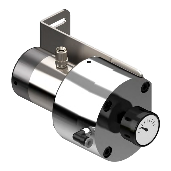
04. PRODUCT OVERVIEW WEEPLESS MVR INTRODUCTION (76624) The material regulator valve (MVR) is an air operated The tapered area on the needle and the fluid port valve that slides. It has a tapered needle and specially configuration let fluid flow through the MVR proportional designed fluid ports to permit precise regulation to the air pressure control signal. -
Page 14: Specifications
04. PRODUCT OVERVIEW WEEPLESS MVR ASSEMBLY SPECIFICATIONS–76624 Pressures Ratings Maximum Air Pressure 100 psig (6.9 bar) Maximum Fluid Pressure 3000 psig (206.85 bar) Flow Rate (Dependent upon material viscosity and needle used) Part No. #0 Needle – Ultra Low Flow 76623-00 #1 Needle –... -
Page 15: Servicing
05. SERVICING WEEPLESS MVR SERVICING PRELIMINARY PROCEDURES Before the removal of the MVR for servicing or COMMON MVR ISSUES repair, do the following: 1. Improperly filtered fluids cause the most common operation issues with the (MVR). 1. Flush the MVR with the system purge. Particulates and residue in the MVR can plug the fluid 2. - Page 16 05. SERVICING This page intentionally left blank. LN-9225-00 R8.0 (03/2024) 12 / 42 www.carlisleft.com...
-
Page 17: Maintenance
06. MAINTENANCE DISASSEMBLY, INSPECTION, AND ASSEMBLY DISASSEMBLY Put the MVR (a) in a bench vise (not included). Use padded jaws (b) to protect the MVR valve housing from damage. Loosen the top four MVR upper housing bolts (c) evenly in an alternating pattern. NOTICE When the bolts are loosened, the internal spring load will force the MVR housing halves to separate. - Page 18 06. MAINTENANCE 4. Remove the M4 x 20 mm screw (f) and upper diaphragm support (g). 5. Remove the air diaphragms (h). 6. Remove the bottom diaphragm support (i). NOTICE Set the upper and lower diaphragm supports on a clean, lint-free surface. 7.
- Page 19 06. MAINTENANCE 9. Flip the assembly and re-tighten the vise. 10. Remove fittings (l & m). NOTICE Set the fittings on a clean, lint-free surface. 11. Remove the four screws (n), fluid housing end cap (o), and the fluid housing (p) assembly from the lower housing (e).
- Page 20 06. MAINTENANCE NOTICE Only remove the rolled steel pin if it gets bent during the disassembly procedure and needs to be replaced. Disregard this step if the pin is in good condition. 12. If damaged or bent, remove the rolled steel pin (q) from the fluid housing with a vice or pliers.
- Page 21 06. MAINTENANCE 18. Remove the seal retainer (u) from the head of the bushing guide (v). 19. From the pulled guide bushing (v) assemblies, remove the following: • Small backup rings (w) • Small O-rings (x) • Large high-pressure backup rings (y) •...
-
Page 22: Weepless Mvr Inspection
06. MAINTENANCE INSPECTION Use an applicable solvent and clean the remaining material from all MVR parts. Examine the following parts for wear and damage: 1. The needle (k) must measure the same diameter at the ends and center. Replace the needle and bushing as a set if the needle does not measure the same at the three locations or if there are scores, scratches, or damage to the needle. - Page 23 06. MAINTENANCE 5. Replace fittings (L and m) if they leak, are worn, damaged, or have thread damage. 6. Examine the edges of the upper (g) and lower (i) diaphragm supports for raised and sharp nicks that can damage the diaphragms. NOTICE Minor nicks can be filed, but if they cannot be smoothed, the support must be replaced.
-
Page 24: Weepless Mvr Assembly
06. MAINTENANCE ASSEMBLY Needle Preassembly 1. Assemble the upper diaphragm support washer (g) onto the screw (f). NOTICE The radius side and edges (ee) of the upper diaphragm support washer points away from the bottom of the screw when correctly assembled. NOTICE While not required, it is recommended that the... - Page 25 06. MAINTENANCE 3. Put the lower diaphragm support washer (i) on top of the diaphragms. NOTICE The radius side and edges (ee) of the lower diaphragm support washer points at the diaphragms when correctly assembled. 4. Apply a small quantity of blue Loctite 243 (not included) onto the screw threads.
- Page 26 06. MAINTENANCE 6. Tighten the screw (f) and diaphragm assembly onto the needle. NOTICE When the needle is tightened, it can be held in place with a padded vise or pliers, or with a second Allen wrench in the hex socket at the bottom of the needle. CAUTION The needle has a precision machined surface.
- Page 27 06. MAINTENANCE Guide Bushing Assembly 1. Press the O-ring loaded U-cup seal (aa) into the foot of the guide bushing (v) until fully seated. NOTICE The foot of the guide bushing is identified by the lack of threaded holes that exist only on the head of the guide bushing.
- Page 28 06. MAINTENANCE 6. Put the seal retainer (u) onto the bushing guide head. Make sure the alignment pin on the seal retainer is set into one of the two non-threaded holes. 7. Repeat steps 1 through 6 to assemble the second guide bushing assembly.
- Page 29 06. MAINTENANCE CAUTION Carefully move the fluid housing onto a clean, lint-free surface during reassembly. 1. If required, install the new rolled steel pin (q) into the pin hole (gg) in the bottom of the fluid housing. 2. Apply Teflon tape (not included) to the fitting's threads.
- Page 30 06. MAINTENANCE 6. Align the weep hole (hh) in the fluid housing end cap (o) to the same side as the flat mounting face on the lower housing (e) and lay it on top of the fluid housing. 7. Apply a small quantity of blue Loctite 243 (not included) onto the screw threads (n).
- Page 31 06. MAINTENANCE 11. Apply a small quantity of petroleum jelly (not included) onto the outside diameter of the needle. 12. Align the needle and diaphragm assembly into the needle bushing in the fluid housing assembly. Apply petroleum 13. Carefully slide the needle into the bushing until the jelly here lower diaphragm support rests on the top of the spring.
- Page 32 06. MAINTENANCE 16. Tighten the screws in a crisscross sequence pattern in a minimum of two steps. NOTICE While the bolts are turned, the internal spring load will keep force against the MVR housing halves. It will be necessary to keep equal tension on the housing bolts to avoid damage to the MVR's internal components.
- Page 33 06. MAINTENANCE This page intentionally left blank. www.carlisleft.com 29 / 42 LN-9225-00 R8.0 (03/2024)
-
Page 34: Weepless Mvr Assembly Parts
06. MAINTENANCE WEEPLESS MVR ASSEMBLY LN-9225-00 R8.0 (03/2024) 30 / 42 www.carlisleft.com... - Page 35 06. MAINTENANCE WEEPLESS MVR ASSEMBLY Part No. Description Qty. Notes GA-338 Pressure Regulator, 0-160 psi Apply Teflon tape (not included) 8532-40C Screw, Socket Head Cap, 5/16-18 UNC x 1.25"L A10508-00 Upper Housing (After 12/03) 8301-16C Screw, Socket Head Cap, M4 X 20 Apply Blue Loctite 243 (not included) TR-SSF-506 Upper Diaphragm Support Washer...
- Page 36 06. MAINTENANCE RECOMMENDED SPARE PARTS Part No. Description TR-SSMM-151 Air Diaphragm, MVR Assembly 78783-00 Compression Spring, MVR 77049-00 Backup Ring for 2-109 O-Ring, High-Pressure 79001-28 O-Ring, .299 I.D. x .103 c/s, Solvent Proof 76625-00 Backup Ring for 2-020 O-Ring, High-Pressure 79001-21 O-Ring, .864 I.D.
- Page 37 06. MAINTENANCE A, C 2 A, B 5 A, C Needle Taper A, C A, B 4 A, C See Detail D A, C A - All seals must be installed with the O-rings A, C pointed to the needle taper (inward), as shown above.
- Page 38 06. MAINTENANCE 5 A, B 7 A, C Needle Taper A, C A, B 3 A, C A - All seals must be installed with the O-rings pointed to the needle taper (inward), as shown above. B - Lightly lubricate the O-rings with petroleum jelly before installing the guide bushings into the housing.
-
Page 39: Weepless Mvr Fluid Needles
06. MAINTENANCE WEEPLESS MVR FLUID NEEDLES NOTICE To replace the MVR fluid needles, refer to the image below and the Weepless MVR Assembly "Part Number Options Chart/column C" on page 31 to determine the correct size and part number. The needles have grooves at the top. The number of grooves (highlighted in red for this example) correlates to the dash number of the parent part number. - Page 40 06. MAINTENANCE This page intentionally left blank. LN-9225-00 R8.0 (03/2024) 36 / 42 www.carlisleft.com...
-
Page 41: Technical Service Bulletins
07. TECHNICAL SERVICE BULLETIN TECHNICAL SERVICE BULLETIN Subject: Line Pressure Increase During Trigger-Off (Refer to 76624 Weepless MVR Assembly and LAFX4001 Please view the drawing shown below. This valve can Valve Assembly). be used as a preliminary shut-off valve to interrupt the fluid pressure to the Weepless MVR Assembly. - Page 42 07. TECHNICAL SERVICE BULLETIN This page intentionally left blank. LN-9225-00 R8.0 (03/2024) 38 / 42 www.carlisleft.com...
-
Page 43: Manual Revisions
08. MANUAL REVISIONS MANUAL CHANGE SUMMARY Date Description Version Added and updated manual 09/08/2000 05/31/2005 Added and updated parts and volumetric charts 04/09/2013 Added and updated parts and volumetric charts Added and updated parts and volumetric charts 03/01/2021 Update to new manual format 03/13/2024 Revised design, added new information, images, and switched to versioning. - Page 44 08. MANUAL REVISIONS This page intentionally left blank. LN-9225-00 R8.0 (03/2024) 40 / 42 www.carlisleft.com...
-
Page 45: Warranty
This product is covered by Carlisle Fluid Technologies’ materials and workmanship limited warranty. The use of parts or accessories from sources other than Carlisle Fluid Technologies will void all warranties. Failure to follow reasonable maintenance guidance provided can invalidate the warranty. - Page 46 Carlisle Fluid Technologies is a global leader in innovative finishing technologies. Carlisle Fluid Technologies reserves the right to modify equipment specifications without prior notice. BGK™, Binks®, DeVilbiss®, Hosco®, MS®, and Ransburg® are registered trademarks of Carlisle Fluid Technologies, LLC. ©2024 Carlisle Fluid Technologies, LLC. All rights reserved.
Need help?
Do you have a question about the Ransburg IntelliFlow WEEPLESS MVR 76624 and is the answer not in the manual?
Questions and answers