Table of Contents
Advertisement
Quick Links
Advertisement
Table of Contents

Subscribe to Our Youtube Channel
Related Manuals for Carlisle Ransburg Color Select System CCV-6100


Summary of Contents for Carlisle Ransburg Color Select System CCV-6100
- Page 1 SERVICE MANUAL Color Select System Model: CCV-6100 IMPORTANT: Before using this equipment, carefully read SAFETY PRECAUTIONS and all instructions in this manual. Keep this Service Manual for future reference. CS-95-01-R3 (09/2018) 1 / 25 www.carlisleft.com...
- Page 2 MANUAL CHANGES NOTE: This manual has been changed from revision CS-95-01.2 to revision CS-95-01-R3. Reasons for this change are noted under “Manual Change Summary” inside the back cover of this manual. CS-95-01-R3 (09/2018) 2 / 25 www.carlisleft.com...
-
Page 3: Table Of Contents
CONTENTS CONTENTS SAFETY: Safety Precautions ..............................4 Hazards / Safeguards ..............................5 INTRODUCTION: 9-16 Description ................................9 Specifications ................................10 Color Select System Model Identification ........................ 10 CCV-61XX-XXX-Color Select System ........................11 CCV-61(XX)-XXX-Number of Color Valves ......................11 CCV-61XX-(X)XX-Air Push Valves ...........................11 CCV-61XX-X(X)X-Check Valves ..........................11 CCV-61XX-XX(X)-Fluid Inlet Fittings ........................11 CCV-51XX Color Valve Stack Assembly ......................... -
Page 4: Safety
SAFETY SAFETY SAFETY PRECAUTIONS Before operating, maintaining or servicing any Ransburg WA R N I N G electrostatic coating system, read and understand all of the technical and safety literature for your Ransburg products. † The user MUST read and be familiar with the This manual contains information that is important for you Safety Section in this manual and the Ransburg to know and understand. -
Page 5: Hazards / Safeguards
SAFETY AREA SAFEGUARDS HAZARD Tells where hazards Tells how to avoid the hazard. Tells what the hazard is. may occur. Fire Hazard Spray Area Fire extinguishing equipment must be present in the Improper or inadequate spray area and tested periodically. operation and maintenance procedures will cause a fire Spray areas must be kept clean to prevent the... - Page 6 SAFETY AREA SAFEGUARDS HAZARD Tells where hazards Tells how to avoid the hazard. Tells what the hazard is. may occur. Explosion Hazard Spray Area Improper or inadequate Electrostatic arcing must be prevented. Safe sparking operation and maintenance distance must be maintained between the parts being procedures will cause a coated and the applicator.
- Page 7 SAFETY AREA SAFEGUARDS HAZARD Tells where hazards Tells how to avoid the hazard. Tells what the hazard is. may occur. Spray Area / Electrical Discharge High Voltage There is a high voltage device Parts being sprayed and operators in the spray Equipment that can induce an electrical area must be properly grounded.
- Page 8 SAFETY AREA SAFEGUARDS HAZARD Tells where hazards Tells how to avoid the hazard. Tells what the hazard is. may occur. Electrical Discharge Electrical Unless specifically approved for use in hazardous Equipment locations, the power supply, control cabinet, and all High voltage equipment is utilized in the process.
-
Page 9: Introduction
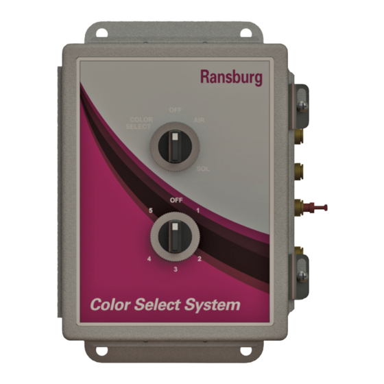
INTRODUCTION INTRODUCTION DESCRIPTION Main Box Color Select System The CCV-6100 Color Select System is a manually controlled The main box consists of two six-position pneumatic switch- es. The top switch switches between off, air solvent and pneumatic color change system. The system consists of color. -
Page 10: Specifications
INTRODUCTION SPECIFICATIONS Air Requirements: 70-100 psig(4.8-6.9 bar) Operating Pressure Air Inlet / Outlet Connections: 1/4” OD Tubing Fluid Pressure: 300 psig (20.6 bar) max. Fluid Inlet: 1/4” NPT (F) X 2 ports (Fittings installed 3/8” OD tubing) Fluid Outlets: 1/4” NPT (F) (Fitting installed a 3/8” OD tubing) Fluid Flow: 3800 cc/min @ 47 psi pressure drop (Paint viscosity @ 700 centipoise) Varies according to material pressure and viscosity. -
Page 11: Ccv-61Xx-Xxx-Color Select System
INTRODUCTION CCV-61XX-XXX - CCV-61XX-X(X)X - COLOR SELECT SYSTEM CHECK VALVES Includes the main box, top block, solvent valve and 1/4 inch (Selection 0, 1). This number indicates whether check O.D. poly tubing. The solvent valve is always supplied with valves are supplied on the paint inlet valves. Check valves a solvent proof check valve and a 3/8-inch ODT stainless are used to prevent materials from contaminating each other steel female elbow for fluid inlet. -
Page 12: Ccv-51Xx Color Valve Stack Assembly
INTRODUCTION CCV-51XX COLOR VALVE STACK ASSEMBLY The CCV-403-SS valve mounted at this position is used for solvent flushing of the manifold assembly. Connect the solvent feed line to this valve. (Check valve is always used on input port of CCV). SS-10022* Cap Screw (4) required GA-338 Gauge HAR-503-1 Air Regulator... -
Page 13: Lpne5002-00 Color Select Box (Master)
INTRODUCTION LPNE5002-00 COLOR SELECT BOX (MASTER) LPNE5003-00 COLOR SELECT BOX (ADD-ON) CS-95-01-R3 (09/2018) 13 / 25 www.carlisleft.com... - Page 14 INTRODUCTION SELECTOR SWITCH FUNCTIONS Position Description LPNE5002-00 LPNE5003-00 Color Select Supplies air to all color select switches Off Stops all air flow Supplies air to Air Push Valve Supplies air to Solvent Push Valve Color - Off Off position for individual Color Select Valves (activates next valve) Color - 1 - 5 Supplies air to corresponding Color Select Valve Color - Off...
- Page 15 INTRODUCTION LPNE5002-00 Color Select Box (Master) LPNE5003-00 Color Select Box (Add-on) Figure 4: Color Select Box CS-95-01-R3 (09/2018) 15 / 25 www.carlisleft.com...
-
Page 16: Color Select Boxes
INTRODUCTION COLOR SELECT BOXES Description Item # Position LPNE5002-00 LPNE5003-00 LPNE0005-01 Color Select Enclosure 41-FP-1011 Plug, #10-32 41-FTP-1023 Connector Fitting 5/32 Tube x 10-32 41-BAS-1000 Logic Base 41-VAP-1004 Air Piloted Valve, “NOT” Logic (No) 41-FTP-1015 Tube Reducer, 5/32” x 1/4” 41-VMC-1002 Manual Control Valve (3 Way, 6 Position) 41-FBH-1000... -
Page 17: Installation
INSTALLATION INSTALLATION Mounting Solvent Connection The solvent is connected in the same way as the Coating The Color Select Box and the Color Change Valve stack Material, using 3/8-inch OD tubing. have mounting brackets for easy mounting. The Color Select Boxes may be mounted using the pattern supplied in this manual (See Figure 10). -
Page 18: Dimensions (Boxes, Mounting)
INSTALLATION Color Select Boxes Dimensions Mounting Dimensions The Color Select Box have mounting brackets for easy mounting. The Color Select Boxes may be mounted using the pattern at right. Mounting hardware can be any type of a 6mm [1/4-inch] bolt with washers. -
Page 19: Typical Color Selectsystem Installation
INSTALLATION Figure 8: Typical Color Select System Installation CS-95-01-R3 (09/2018) 19 / 25 www.carlisleft.com... -
Page 20: Installation Diagram
INSTALLATION Figure 9: Installation Diagram CS-95-01-R3 (09/2018) 20 / 25 www.carlisleft.com... -
Page 21: Operation
OPERATION OPERATION Installation and Operation Overview The flow of the coating material is controlled by selecting The coating material is supplied from the users pressur- the proper color number on the Color Select Boxes. If two ized system that may be a pressure tank, paint circulating Color Select Boxes are used, all Color Select Switches not system or other suitable pressure paint supply system. -
Page 22: Maintenance
MAINTENANCE MAINTENANCE COLOR CHANGE VALVES COLOR SELECT BOXES Cleaning Air Switch Removal The valve and associated parts through which fluid passes Disconnect all air lines to the air switch. should be cleaned after use by flushing with an appropriate solvent. While flushing, the valve should be triggered While holding the front of the air switch, loosen nut on rear several times in order to flush particles from the seat and of air switch and remove nut. -
Page 23: Troubleshooting
MAINTENANCE TROUBLESHOOTING GUIDE General Problem Possible Cause Solution DELIVERY Fluid No main supply air Turn supply air on or reconnect to box No color selected Select a color Wrong color selected Select proper color No paint connected to CCV Reconnect paint or select proper color Paint not pressurized Check users supply No main supply air... -
Page 24: Manual Change Summary
MANUAL CHANGES MANUAL CHANGE SUMMARY CS-95-01-R3 - Replaces CS-95-01.2 with the folowing changes: Change Description Page(s) Update manual to new template All Pages New Image Cover Update Safety section New text and image New images and tables 13-16 Remove unneeded page Add new text and images New image Delete text and consolidate into one page... - Page 25 This product is covered by Carlisle Fluid Technologies materials and workmanship limited warranty. The use of any parts or accessories, from a source other than Carlisle Fluid Technologies, will void all warranties. For specific warranty information please contact Carlisle Fluid Technologies.
Need help?
Do you have a question about the Ransburg Color Select System CCV-6100 and is the answer not in the manual?
Questions and answers