Table of Contents
Advertisement
Quick Links
Advertisement
Table of Contents

Subscribe to Our Youtube Channel
Related Manuals for Carlisle ms 8132 0 Series


Summary of Contents for Carlisle ms 8132 0 Series
- Page 1 SERVICE MANUAL MS Powder Kitchen PK V Model: 8132X0 IMPORTANT: Before using this equipment, carefully read SAFETY PRECAUTIONS and all instructions in this manual. Keep this Service Manual for future reference. PA-19-02-R0 (03/2019) 1 / 51 www.carlisleft.com...
-
Page 2: Table Of Contents
CONTENTS CONTENTS SAFETY: Safety Precautions ..............................3 Hazards / Safeguards ..............................4 INTRODUCTION: Description ................................8 INSTALLATION: Supply Connection ..............................9 OVERVIEW: 10-17 Powder Kitchen Overview ............................10 Level Sensor Probe ..............................11 Ultrasonic Sieve Test and Setup ..........................12 Sieve Parameter Overview ............................ -
Page 3: Safety
This information relates to USER SAFETY and safety literature for your equipment, contact your local and PREVENTING EQUIPMENT PROBLEMS. To help you Carlisle Fluid Technologies representative or Carlisle Fluid recognize this information, we use the following symbols. Technologies technical support. -
Page 4: Hazards / Safeguards
SAFETY Return To Contents AREA SAFEGUARDS HAZARD Tells where hazards Tells how to avoid the hazard. Tells what the hazard is. may occur. Fire Hazard Spray Area Fire extinguishing equipment must be present in the Improper or inadequate spray area and tested periodically. operation and maintenance procedures will cause a fire Spray areas must be kept clean to prevent the... - Page 5 SAFETY Return To Contents AREA SAFEGUARDS HAZARD Tells where hazards Tells how to avoid the hazard. Tells what the hazard is. may occur. Explosion Hazard Spray Area Improper or inadequate Electrostatic arcing must be prevented. Safe sparking operation and maintenance distance must be maintained between the parts being procedures will cause a coated and the applicator.
- Page 6 SAFETY Return To Contents AREA SAFEGUARDS HAZARD Tells where hazards Tells how to avoid the hazard. Tells what the hazard is. may occur. Spray Area / Electrical Discharge High Voltage There is a high voltage device Parts being sprayed and operators in the spray Equipment that can induce an electrical area must be properly grounded.
- Page 7 SAFETY Return To Contents AREA SAFEGUARDS HAZARD Tells where hazards Tells how to avoid the hazard. Tells what the hazard is. may occur. Electrical Discharge Electrical Unless specifically approved for use in hazardous Equipment locations, the power supply, control cabinet, and all High voltage equipment is utilized in the process.
-
Page 8: Introduction
INTRODUCTION Return To Contents INTRODUCTION DESCRIPTION The PK V Powder Kitchen has an integrated control unit, When using the PK V, the powder box is placed on the designed for simple, clean handling of powders, allowing vibrating table. The P50 fresh-feed pump descends into for quick color changes. -
Page 9: Installation
INSTALLATION Return To Contents INSTALLATION SUPPLY CONNECTION Pneumatic Connection Compressed air supply 4-6 bar (48-87 psi) Compressed Air Quality Moisture, Particulate, & Oil filtered to accordance of standard ISO 8573-1 Compressed Air Demand The pressure and volume required depends on the number of guns, gun slots, and color change frequency. -
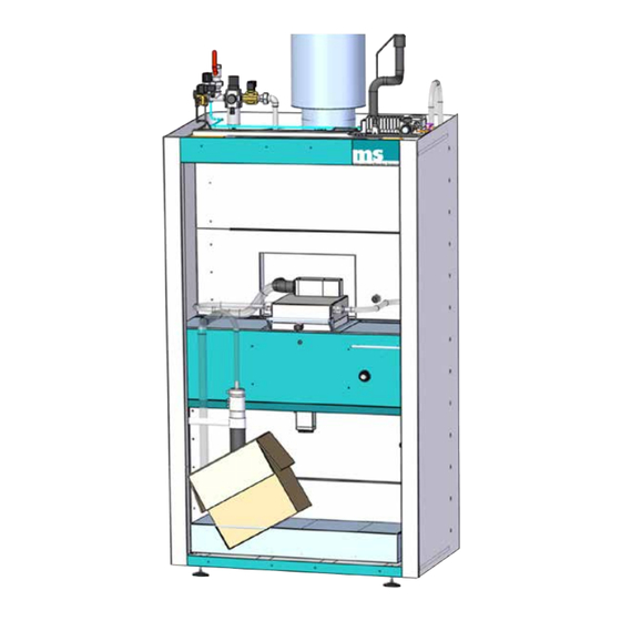
Page 10: Overview
OPERATION Return To Contents OVERVIEW POWDER KITCHEN OVERVIEW The powder hopper (5) is delivered fresh powder by the P50 fresh-feed powder pump (6) - and reclaimed powder from cyclone, if equipped. Main air is supplied to the PK V Maintenance unit (1) The vibrating table (7) holds the powder supply container for operation. -
Page 11: Level Sensor Probe
OPERATION Return To Contents LEVEL SENSOR PROBE Powder Pot Probe Cleaning The level sensor probes have an automatic cleaning Probe Cleaning Pulse Duration 1.00 sec. function in which a pulse of air is delivered to clean the Probe Cleaning Cycle Time 100 sec. -
Page 12: Ultrasonic Sieve Test And Setup
OPERATION Return To Contents Upper Sensor Set Frequency value to 100 Hz as initial starting point. The KV (intensity) value is typically kept at 100kv. • Gray - Powder level below sensor • Green - Level sensor blocked, high level of powder within hopper, all reclaim, and fresh feed functions Sieve Parameters ◀... -
Page 13: Sieve Parameter Overview
OPERATION Return To Contents SIEVE PARAMETER OVERVIEW Sieve Parameters ◀ kV (Intensity) 100 kV Standard Disable ◀ Sieve Amplitude Frequency 237 Hz Sweep Pulse SIEVE PARAMETER OVERVIEW Item # Description kV (Intensity) - Intensity of the sieve screen. Typically set at 100kV Frequency - Frequency of the sieve screen, essentially the “vibration”... -
Page 14: Powder Hopper Cleaning
OPERATION Return To Contents Too high of pressure causes volcano-like bubbles to • Pressurization Time – Duration of time the hopper is escape from the top of the powder level. This results in over-pressurized while both pinch bars are closed delivering more air than powder to the applicators and reduces powder delivery efficiency. -
Page 15: Vacuum Generator (439410) - Function
OPERATION Return To Contents VACCUM GENERATOR (439410) - FUNCTION Vacuum Sequence As part of the P50 Powder Feed pump cycle sequence, the vacuum generator is supplied air pressure to port “P” from the kitchen solenoid assembly located on the roof. Air is drawn from the vacuum port of the pump (A) through the 8mm air tubing (B), passing through the Normally Open (N.O) solenoid (C), into port “V”... - Page 16 OPERATION Return To Contents Air-Pulse Sequence – Solenoid Function Towards the end of the pump cycle is a brief pulse of air pressure to clean the fluidizing tube suction (item 3 below). The air-pulse prevents the membrane of being compacted with powder. An electric signal is sent to close the solenoid (C).
-
Page 17: Manual Hopper Cleaning
OPERATION Return To Contents MANUAL HOPPER CLEANING During a color change and cleanup operation, the powder hopper needs manually cleaned. Upon this function activating, air pressure is supplied to the feed air, dosage air, and gun air lines. This counteracts the cleaning air pressure to prevent powder from entering the gun air tubing and drivers. -
Page 18: Maintenance
MAINTENANCE Return To Contents MAINTENANCE MAINTENANCE SCHEDULE Maintenance schedule below is a general guide. Please note that the components, action, and frequency may vary depending on a variety of factors specific to your application and facility. Maintaining cleanliness, understanding of equipment, and adequate training of personnel will prevent cross-contamination and reduce downtime relating to failed components. -
Page 19: Dismantling The Fluidizing Base
MAINTENANCE Return To Contents DISMANTLING THE T9 INJECTOR SERVICE FLUIDIZING BASE Under service flap beside powder hopper houses the T9 Injector block and venturi nozzles. 1. Using provided MS Wrench (615310) loosen lock nut (445470) PA-19-02-R0 (03/2019) 19 / 51 www.carlisleft.com... - Page 20 MAINTENANCE Return To Contents NOTE † Do not use sharp tools to remove impact fusion as further damage may result to interior surfaces. 2. Slide hose sleeve assembly from powder pump OK TO USE REPLACE 3. Blow interior of venturi nozzle clean with compressed air Inspect for: a.
-
Page 21: Installation Of Replacement Pinch Valve - P50 Powder Pump
MAINTENANCE Return To Contents 7. Insert venturi nozzle into pump bore Push in until fully seated a. Remove installation tool from venturi nozzle. Make sure all powder is removed from pump interior. b. Reinstall powder hose and locknut. Use caution to not force or over tighten lock nut. -
Page 22: Jet Clean (610583) Disassembly
MAINTENANCE Return To Contents JET CLEAN (610583) DISASSEMBLY 2. Align both end caps (6,7) along with positioning the screws (4,5) to the housing (3) threads. Lightly tighten the screws (4,5) only until clamping cones have in- serted into both ends of pinch sleeve. 1. - Page 23 MAINTENANCE Return To Contents 3. Loosen/Remove 3mm Allen-head set screw securing 6. Hold the body stem (A) firmly with one hand and knurled collar. housing sleeve (B) with the opposite hand. a. Remove knurled collar by sliding off stem. a. Pull these two components apart – housing must slide towards the threaded portion of jet clean.
- Page 24 MAINTENANCE Return To Contents 8. Inspect outer O-Rings (P/N 414300) and inner O-Ring (P/N 414310) within the housing sleeve. Replace as needed. 9. Inspect jet ports for powder accumulation and impact fusion. O-Rings Inspect Upon inspection of the Jet Clean, if there is impact fusion: a.
-
Page 25: Jet Clean Reassembly
MAINTENANCE Return To Contents JET CLEAN - REASSEMBLY a. The air thread needs to be aligned within the slot (A). 1. Install O-Rings b. The Allen-screw threaded hole needs to align within slot (B). 4. Reinstall and tighten air fitting using adjustable crescent wrench. -
Page 26: Vacuum Generator (439410) - Disassembly
MAINTENANCE Return To Contents VACCUM GENERATOR (439410) - DISASSEMBLY If powder draw and delivery appears to have reduced it may be due to powder or foreign elements within the vacuum generator. There should be no powder within the vacuum generator. If there is it may be resulting from po- tential damage of the fluidizing membrane (613145). - Page 27 MAINTENANCE Return To Contents 5. Separate components and inspect. 3. Disconnect air tubing from the “P” and “V” port of generator by pushing down on locking collar and pull tubing. a. Vacuum generator is now disconnected and may be serviced. 6.
-
Page 28: Vacuum Generator And Solenoid Reassembly
MAINTENANCE Return To Contents 8. Assemble in reverse order. To remove solenoid assembly: 3. Disconnect air tubing from two solenoid ports.The solenoid is now disconnected. VACCUM GENERATOR AND SOLENOID REASSEMBLY 1. Loosen Phillips-head screw from connecting cable. Carefully pull plug from solenoid to disconnect. 1. - Page 29 MAINTENANCE Return To Contents 2. Properly align terminals and attach connecting cable. Secure connector to solenoid using small Phillips- head screwdriver. 4. Insert 10mm air tubing from solenoid outlet to “V” port of vacuum generator. 5. Insert supply line (6mm) to “P” port of vacuum generator.
-
Page 30: General Fastener Torque Reference Guide
MAINTENANCE Return To Contents GENERAL FASTENER TORQUE REFERENCE GUIDE Strength Marking 8.8 and 9.8 10.9 12.9 Max Torque Max Torque Max Torque Max Torque Max Torque Diameter Wrench Size Ft/Lbs Ft/Lbs Ft/Lbs Ft/Lbs Ft/Lbs 5.5mm 10mm 13mm 16mm 18mm 21mm 24mm 27mm 30mm... -
Page 31: Parts Identification
PARTS IDENTIFICATION Return To Contents PARTS IDENTIFICATION POWDER KITCHEN PK V Item # Part # Description 414101 Vacuum cleaner hose 98455 Valve Module PK V Reference Only Powder hopper PK V 415450 Recovery hose Reference Only Vibrating table 913391 Linear unit 613835 Over pressure hose 415450... -
Page 32: Hose Squeeze
PARTS IDENTIFICATION Return To Contents HOSE SQUEEZE Description Item No. Part No. 447640 Compact cylinder Ø63, Hub 20 Source Local Angle screw connection 90° D=6mm G1/4” 450250 Pressure regulator, Manometer integrated in the turret 613408-01 Sealing plug PK V PA-19-02-R0 (03/2019) 32 / 51 www.carlisleft.com... -
Page 33: Pk V T9 Injector
PARTS IDENTIFICATION Return To Contents PK V T9 INJECTOR Item # Part # Description 445450-100 Venturi Nozzle (Qty of 100) 445450-50 Venturi Nozzle (Qty of 50) 445450-25 Venturi Nozzle (Qty of 25) 613360 Grounding Sleeve Assembly 445141 O-Ring 445470 Locknut POM injector T9 810190 Powder Feed Hose 11x16.5 449964... -
Page 34: P50 Pump Vacuum Assembly
PARTS IDENTIFICATION Return To Contents P50 PUMP VACUUM ASSEMBLY Item No. Description For Reference P50 Fresh-Feed Powder Pump 410020 Cylinder Head Screw M5x12 614100 Pump Cleaning Attachment 610574 Adapter Source Local Hose Clamp 19-44mm 414110 End sleeve d32 414101 Vacuum Hose d41 1.5 meters PA-19-02-R0 (03/2019) 34 / 51... -
Page 35: Vacuum Cleaner Hose Set (610575) - Spare Parts
PARTS IDENTIFICATION Return To Contents VACCUM CLEANER HOSE SET (610575) - SPARE PARTS Item # Part # Description 414101 Vacuum Hose 41x31mm 10 meters 414190 Jet Clean Grip 414180 Jet Clean Extension Tube 50cm 414170 Jet Clean Hard Floor Brush 414160 Jet Clean Crevice Nozzle 32mm 414150... -
Page 36: Ms Ultrasonic Sleeve
PARTS IDENTIFICATION Return To Contents MS ULTRASONIC SLEEVE Part No. Description 810070 MS Converter US-60 MS Ultrasonic Sieve Fits PK V24 811190 MS Ultrasonic sieve US-60 100µm PK-V24 811195 MS Ultrasonic sieve US-60 125µm PK-V24 811200 MS Ultrasonic sieve US-60 140µm PK-V24 811205 MS Ultrasonic sieve US-60 160µm PK-V24 811210... -
Page 37: Ms P50 Powder Pump - 810270
PARTS IDENTIFICATION Return To Contents MS P50 POWDER PUMP - 810270 Capacity 400 – 5000 g/min Pump Outlet Conveying Distance Up to 40 meters with Ø19mm powder hose Compressed Air Supply Powder Pump 6 bar / 87 psi Feed Air Fluid Air to Fluidizing Tips Pneumatic Data... - Page 38 PARTS IDENTIFICATION Return To Contents P50 POWDER PUMP Item No. Part No. Description 613140 Fluidizing Tube Suction 20 411670 Replacement Pinch Sleeve 613145 Fluidizing Tube Suction 40 448015 O-Ring 1.5x30mm 449784 O-Ring 1.5x69mm 426625 Fluid Candle Source Local Screw in union straight G1/8“ 6mm brass 613165 Casing pipe 75 613170...
-
Page 39: Powder Kitchen Pk V Light
PARTS IDENTIFICATION Return To Contents POWDER KITCHEN PK V LIGHT Description Item No. Part No. 439909 Fluorescent tube 18W REGULATING FLAP PK V Description Item No. Part No. Reference Only Thrust bearing 414761 Cylinder 20x100mm Reference Only Double knuckle joint M8-16 PA-19-02-R0 (03/2019) 39 / 51 www.carlisleft.com... -
Page 40: Powder Kitchen Roof Overview
PARTS IDENTIFICATION Return To Contents POWDER KITCHEN ROOF OVERVIEW Item No. Part No. Description 610583 Jet Clean Reference Only Air hose Ø10 supply air ejector 414101 Vacuum cleaner hose 32x41mm 415450 Recovery hose 19x26mm Reference Only Air hose Ø16 powder pump down 613455 Solenoid Assembly 461050... -
Page 41: Pk V Maintenance Unit
PARTS IDENTIFICATION Return To Contents PK V MAINTENANCE UNIT Item No. Part No. Description 461059 Pressure Regulator Air Maintenance Unit 0.5-7 bar 461054 Filter Regulator 3/4” Air Maintenance Unit 0.5-7 bar 415952 Solenoid Valve 3/4” 24V 454277 Membrane for Solenoid Valve 3/4” 24V 415882 Solenoid Valve 1/2”... -
Page 42: Solenoid Valve Assembly - Parts List
PARTS IDENTIFICATION Return To Contents PA-19-02-R0 (03/2019) 42 / 51 www.carlisleft.com... - Page 43 PARTS IDENTIFICATION Return To Contents SOLENOID VALVE ASSEMBLY Item No. Part No. Description 450281 Manometer 0-10bar / Cyl. Powder pump lower 461051 Pressure regulator / 1bar Reference Only Air hose Ø10mm 461050 Cleaning valve dosing Reference Only Air hose Ø6mm Reference Only Air hose Ø10mm Reference Only...
-
Page 44: Pk V Vacuum Assembly
PARTS IDENTIFICATION Return To Contents PK V VACUUM ASSEMBLY (Located under service flap to left of powder hopper) Item No. Part No. Description 461052 Under pressure solenoid valve 439410 Vacuum Generator Reference Only Air hose Ø6mm to “P” port of vacuum generator Reference Only Air hose Ø6mm supplying air to pulse Reference Only... -
Page 45: Pk V Linear Drive
PARTS IDENTIFICATION Return To Contents PK V LINEAR DRIVE Item No. Part No. Description Reference Only Flange mounting Ø32 lift=500 450724 Standard cylinder Ø32 Hub=500 Reference Only Guide rail 720mm 450675 Housing floating bearing LL 450674 Housing fixed bearing Reference Only Holder fresh powder pump 810270 MS powder pump P50... -
Page 46: Pk V Vibrating Table / Blow Gun
PARTS IDENTIFICATION Return To Contents PK V VIBRATING TABLE Description Item No. Part No. 613551.02 Spring assembly vibrating table 416110 Vibrator 100% without condenser 450184 Vibrating table welded PK V BLOW GUN Description Item No. Part No. 447695 Blow gun plastic 447696 Spiral hose PA-19-02-R0 (03/2019) -
Page 47: Pk V Powder Hopper
PARTS IDENTIFICATION Return To Contents PK V POWDER HOPPER Item No. Part No. Description 449865-02 Sealing Cord, 2 meters 451316 Coupling, Female Connection with Hose Nozzle 613357 Handle Assembly, Complete 449845 Single End Cam Plate Only (2 required for replacing both plates) Reference Only Injector block T9 12-subject cpl. - Page 48 PARTS IDENTIFICATION Return To Contents PK V POWDER HOPPER (Cont.) Item No. Part No. Description 444390 Vibrating Element, Cylindrical 613401 Fluid Base PK V24 450084 O-Ring 1.5x50 421950 Replacement Sleeve Pinch Valve 612870 Vibrator BM-A50/3 cpl. (auf 50% set) 447065 Level Sensor Cable, 5m, M12 angled 447597 Powder Level Sensor Control...
-
Page 49: Recommended Spare Parts
PARTS IDENTIFICATION Return To Contents RECOMMENDED SPARE PARTS Part No. Description Function Impact 449865-02 Sealing Cord Ø6mm Gasket material for System Cleaning powder hopper lid 810070 MS Converter US-60 Converts Energy for Sieve Will Not Function Ultrasonic Sieve See Chart MS Ultrasonic Sieve Sieve Screen for Poor Powder Sieve for options Sieving Powder Performance 810077 MS Convertor Connecting Sends Power to Convertor Sieve Will Not Function Cable, 10m 613625 US-60 Fitting Complete Connects Sieve Screen Sieve Will Not Function Assembly and Convertor 613405... - Page 50 PARTS IDENTIFICATION Return To Contents RECOMMENDED SPARE PARTS Part No. Description Function Impact 446310 O-Ring Ø46x2.5mm, Black O-Ring for Hopper Poor System Cleaning Vent Pinch Valve 449964 O-Ring Ø16x1.5mm, Black O-Ring for Base of Pump Poor Pump Performance/ Injector Block Delivery 810190 11mm Anti-Static Powder Hose Powder Feed Hose to If hose leaks powder, poor color Applicators change for associating gun 448060 Grub Screw M10 Retains Drive Nozzle Unable to use Pump 461053 Vacuum Injector Creates Suction in Fresh Poor Fresh Feed Performance Feed Pump 613140 Fluidizing Tube Suction, 20 Filter for Fresh Feed Pump Poor Fresh Feed Performance...
- Page 51 This product is covered by Carlisle Fluid Technologies materials and workmanship limited warranty. The use of any parts or accessories, from a source other than Carlisle Fluid Technologies, will void all warranties. For specific warranty information please contact Carlisle Fluid Technologies.
Need help?
Do you have a question about the ms 8132 0 Series and is the answer not in the manual?
Questions and answers