
Related Manuals for Carlisle BINKS E420


Summary of Contents for Carlisle BINKS E420
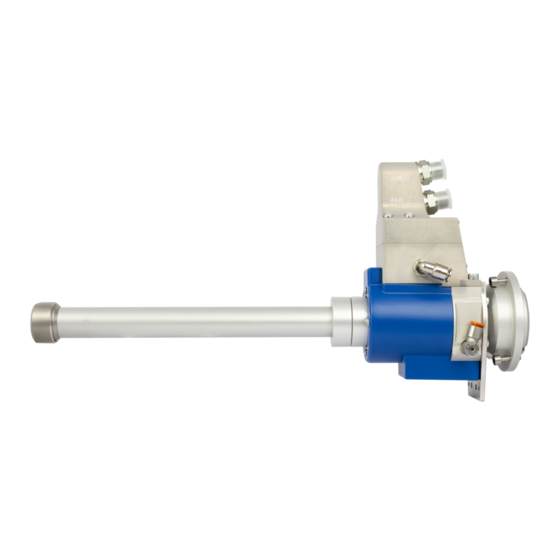
- Page 1 OPERATING MANUAL Binks E420 Swiveling applicator for Robotic Sealing Applications 77-3345 R1.1 (06/2022) www.carlisleft.com...
-
Page 2: Table Of Contents
Content: 1. Safety information ..............3 1.1 Warnings ................4 2. Description ................. 5 2.1 Central body ................6 2.2 Swivel housing ................ 8 2.3 Connection housing .............. 11 2.4 Nozzle head ................. 12 2.5 Cylinder assembly ..............13 2.6 Swivel locking bracket ............14 2.7 Mounting flange .............. -
Page 3: Safety Information
If you need further information about this product, please contact your supplier and refer to the “model” and “serial No.” of your equipment. The Binks E420 is designed for safe operation. It’s important that the conditions for safe operation are respected so that accidents and personal injury are prevented. -
Page 4: Warnings
In this manual, the words WARNING, CAUTION and NOTE are used to emphasize important safety information as follows: CAUTION WARNING NOTE in minor ! WARNING Read the following warnings before using this equipment PINCH POINT HAZARD READ THE MANUAL Moving parts can crush and cut. Pinch points are basically any areas where read and all safety, and maintenance... -
Page 5: Description
Due to its flexibility, the Binks E420 is designed for applications: Underbody coating (UBC), Underbody seam sealing (UBS), and Interior seam sealing (ISS). The Binks E420 is designed to handle most types of single component adhesives and sealants with medium to high viscosity. -
Page 6: Central Body
2.1 Central body: The Binks E420 applicator central body contains these main parts: The central body has two main parts which are the extension (1) and the axis (2). The two parts are mounted together with the help of two rings (3) which also act as a lock ring for the swivel housing. - Page 7 2.1 Central body: The central body connects material and air to the nozzle head and the cylinder block, respectively. Two parallel channels supply material up to the nozzle head. A third channel is provided for the material return flow back to the swivel housing. When a version of the applicator without circulation is used material is supplied through all three channels in the central body.
-
Page 8: Swivel Housing
2.2 Swivel housing: The swivel housing supplies the material from the connection housing to the central body and the cylinder unit. The swivel housing consists of three main parts which are the material chamber (1), the air chamber (2), and the solenoid valves (3). The external solenoid valves supply compressed air to the cylinder unit. There is one inlet channel (5) and one return channel (6) in the material housing. - Page 9 2.2 Swivel housing: To keep the swivel housing centered on the central body ball bearings are used, one in the material chamber (1) and one in the air chamber (see page 10). There is a front (2) and a back (3) drainage chamber in the swivel chamber that are both sealed by additional seals (4) to prevent material leakage into the air chamber and onto the car chassis.
- Page 10 2.2 Swivel housing: The pistons are actuated by three monostable 3/2 solenoid valves (1) that are attached to the air housing. They are easily removed and replaced during production, without dismounting the applicator from the robot, should they fail. An 8 mm coupling (2) that is connected to the air chamber supplies the solenoids with compressed air. From the solenoids, compressed air is supplied to the central axis through the air distributor ring (3).
-
Page 11: Connection Housing
The connection housing is designed as the common platform for all external connections to the Binks E420 applicator. The connections for material supply (1) and return (2) are placed in the upper connection piece. The Basic version of the applicator only uses a single nipple (3). -
Page 12: Nozzle Head
2.4 Nozzle head: The nozzle head comes in a variety of different designs depending on the material and method of application used. The nozzle heads are designed to accommodate guided nozzles with standard measurements. Standard nozzle head Square adapter Square adapter and rectangular nozzle head 12 / 62 77-3345 R1.1 (06/2022) www.carlisleft.com... -
Page 13: Cylinder Assembly
2.5 Cylinder assembly: The main part of this assembly is the cylinder block (1) which has three pneumatic cylinders that operate the material valves. In each of the cylinders, a piston (2) is fixed to the valve needle. On top of the cylinder block is a cylinder cover (3) fitted that includes springs (4) that close the material valves. -
Page 14: Swivel Locking Bracket
2.6 Swivel locking bracket: Connected to the swivel housing is the swivel locking bracket, that locks the swivel housing and the connection housing to a fixed point between axis 5 and 6 on the robot. This design makes sure that the connections follow the motion of axis 5. -
Page 15: Mounting Flange
2.7 Mounting flange: The mounting flange (1) is the interface between the Binks E420 applicator and the sixth axis of the robot. Consequently, the design of the mounting flange is robot and manufacturer-dependent. The flange is fixed to the robot using screws (2) where the guide pin (3) locks the flange in position on the robot`s sixth axis. -
Page 16: Tools
2.8 Tools: CAUTION Not using correct tooling might void warranty Standard tools needed for service of the Binks E420 applicator: 2 mm Hex key • 2.5 mm Hex key • 3 mm Hex key • 4 mm Hex key •... -
Page 17: Installation Instructions
To ensure a trouble free operation of the Binks E420 applicator it is very important that the unit is properly installed on the robot. It is also very important that the function of the applicator is carefully checked before start up. - Page 18 3. Installation instructions: NOTE The mounting flange and the swivel lock are only for illustration. Both are depending on the robot manufacturer and type. Before installing the nozzles, it is important to check that the nozzle packings are in their correct positions (1).
- Page 19 3. Installation instructions: The next step in installing the applicator is the swivel locking bracket. The installation instructions on this page show how to install the standard swivel locking bracket. (instructions are shown with an ABB robot and the mounting flange and swivel lock are for illustration purposes) Mount the block (1) to the plate using the two screws (2) note the two guide pins (3).
- Page 20 3. Installation instructions: When the applicator is fixed in the correct position the electrical cables can be connected. First, connect the cable to the applicator, then install the cable to the robot and make the appropriate connections in the control cabinet. The air supply is connected to the applicator with an 8 mm PU-hose to the push-in coupling on the side of the swivel housing (1).
- Page 21 3. Installation instructions: With the applicator properly installed on the robot, the functions of the unit can be tested. First, open the air supply. There must be no sound from leaking air. Check that the solenoid valves are working properly by open and closing each valve from the robot pendant and listen to the sound of the piston in operation.
-
Page 22: Dismounting Instructions
4. Dismounting instructions: WARNING NOTE NOTE Before any service or cleaning action is Clean the unit and all parts surrounding it The mounting flange and the swivel lock are undertaken on the applicator make sure that before removing the applicator. only for illustration. - Page 23 4. Dismounting instructions: Unscrew the three screws (1) holding the applicator to the mounting flange. The screws can be left in the cylinder housing due to their design (2). With the applicator removed from the robot disassembly and service can be performed. Be sure to store all removed parts in a safe place.
-
Page 24: Disassembly Instructions
5. Disassembly instructions: CAUTION NOTE Ensure a proper work bench with a vice with Immediately clean all parts after removal that will be fitted again and inspect “soft jaws” and that access to compressed the cleaned parts for damage and excessive wear and replace if so necessary. air is available to facilitate the work. - Page 25 5. Disassembly instructions: NOTE Always use a vice with ”soft jaws”. Fasten the applicator to a vice with soft jaws (1) then unscrew the three screws (2) and remove the cylinder cover (3) and the springs (4). Remove the seal (5) then push the needles or pull the pistons to a position where you can access the screws (6) that holds the pistons to the needles.
- Page 26 5. Disassembly instructions: The needles can now be pushed to the bottom of the cylinder (1) and pulled out from the central body (2). To separate the central body extension from the central body axis start with unscrewing the three (3) screws holding the two pieces of the lock ring together.
- Page 27 5. Disassembly instructions: CAUTION The surface with cutouts for o-rings on the central body axis is fragile. Do not use a tool to hammer on this fragile area. Remove the three O-rings (1) then unscrew and remove the second piece of the lock ring (3). Separate the central body axis and cylinder block from the swivel housing by first rotating (4) then pull it out (5).
- Page 28 5. Disassembly instructions: With the central body axis (1) taken out from the swivel housing unscrew the three screws (2) holding the cylinder block (3) to the axis (1). Remove three seals (4) and three O-rings (5) from the back of the cylinder block.
- Page 29 5. Disassembly instructions: Pull out the plastic distances (1) then the three distances (2) from the central body axis, tool 6004 0154 11 an be used (see page 16). Remove the seals (3) and O-rings (4) from the distances. The central body parts have all been disassembled and can be cleaned appropriately.
- Page 30 5. Disassembly instructions: Unscrew the four screws (1) holding the cover (2) to the swivel housing and slide it off. Unplug the cable (2) to the solenoid valves. Unscrew the four screws (3) holding the connection housing (4) and swivel housing (5) together, then separate them.
- Page 31 5. Disassembly instructions: NOTE To avoid damages to the sensor cables use caution when removing the connector and plate. Version without circulation and sensors: Unscrew the four screws (1) and remove the connector and plate (2), the cable bridge (3) to the solenoids can be disconnected from the connector (4).
- Page 32 5. Disassembly instructions: CAUTION Unless the pressure or temperature sensors are malfunctioning they should NOT be removed from the lower connection housing. Removing or cleaning either of the sensors may damage them and cause them to malfunction. Unscrew the four screws (1) holding the upper connection (2) housing to the lower connection housing (3).
- Page 33 5. Disassembly instructions: Remove the O-rings for the material (1) and the drainage (2) channels. Unscrew the four screws (3) for the solenoid valve block (4) and remove them. The O-ring (5) can be removed if it needs to be changed or service is required.
- Page 34 5. Disassembly instructions: For the next part of the disassembly special tools 6004 0802 00 (1) and 6004 0802 03 (2) are recommended for easy disassembly. Align the pins and the corresponding holes (3) in both the air housing (4) and the tool (5). When the air housing (4) has been placed in the tool (5) press the air distributor ring (6) out of the air housing using the pressing tool (7).
- Page 35 5. Disassembly instructions: Pull out the four O-rings (1) from the air housing (2). Remove the three O-rings (3) for the solenoid manifold. The air coupling (4) can also be removed and exchanged if so is necessary. For removal of the sealing package, tool 6004 0802 03 needs to be used, see page 16. Begin with placing the tension tool (5) into the cutout (6) in the cup tool (7).
- Page 36 5. Disassembly instructions: Use the tension tool clamp (1) and screw it onto the screw (2) to expand the tension tool (3) so that it gets fastened to the material distribution ring. Screw the tension tool clamp (1) down by using hand force or a flat screwdriver, note the approximate height over the material housing (4).
- Page 37 5. Disassembly instructions: CAUTION A vice is required for the disassembly of the material seal package from the material housing. The material seal package is then pressed out of the materials chamber with the use of a vice. Place the tool sides (1) at each jaw of the vice and tighten the vice to press out (2) the material seal package.
- Page 38 5. Disassembly instructions: When the material seal package has been removed from the swivel housing all the material seals (1) and v-seal (2) can be removed. Material seal package with circulation Material seal package witout circulation With the material seal package taken out from the material chamber remove the four O-rings (3) and the v-seal (4) from the material housing (5).
- Page 39 5. Disassembly instructions: All the parts that are going to be reused in the assembly need to be cleaned. This cleaning process differs depending on the material of the part and application material. All parts included in the applicator should also be inspected for damages that can affect the lifetime of the part itself or other parts that it is in contact with.
-
Page 40: Assembly Instructions
6. Assembly instructions: CAUTION NOTE Ensure a proper work bench with a vice with “soft jaws”. Suitable Before assembly, make sure all spare parts are available (new in lubricant and thread locking compound should also be available. unopened package if so delivered), other parts thoroughly cleaned. Recommended tightening torques: Pressure sensor 10 Nm It is recommended to use the special tools kit for the E420, see page... - Page 41 6. Assembly instructions: Before the connection housing is attached to the swivel housing it needs to be fully assembled. Mount the v-seals (1) in the material housing (2) and the leakage distributor (3) ring. Mount the material seals (4) into the material distributor rings (5). For mounting the seals, tools with article number 6004 0802 00 are used, see page 16.
- Page 42 6. Assembly instructions: CAUTION Ensure a proper work bench with a vice with “soft jaws”. Mount the O-rings (1) in the material housing. Assemble the material seal package, note the guide pins between the different material rings. There are two pins between the material chamber rings (2), three (3) that guide the air distributor ring, and one (4) that prevents rotation of the material seal package.
- Page 43 6. Assembly instructions: CAUTION Ensure a proper work bench with a vice with “soft jaws”. Mount the four O-rings (1) inside of the air housing (2), reattach the air coupling (3) if it has been removed. Mount the four seals (4) inside the air distributor ring (5).
- Page 44 6. Assembly instructions: CAUTION Ensure a proper work bench with a vice with “soft jaws”. When the air housing (1) is placed on top of the air distributor ring and properly aligned with the material housing (2) a vice with soft jaws is used to press the two together. After pressing the internal parts in position fasten the air housing and the material housing together with four screws (2).
- Page 45 6. Assembly instructions: Place the two O-rings for the material channels (1) and the drainage channels (2) in place on the swivel housing. Mount the connection housing to the swivel housing with the two screws in the front (3) and the two screws in the back (4).
- Page 46 6. Assembly instructions: Begin the assembly of the central body axis by mounting the needle seals (1) and the O-rings (2) to the distance pieces. Press the seals (1) in place using a clean flat surface, then check to make sure that the seal is flush against the edges of the distance piece.
- Page 47 6. Assembly instructions: Before the central body axis is mounted to the cylinder block (1) the seals (2) and O-rings (3) need to be mounted into the cylinder block (1). To mount the seals (2) special tool 6004 0154 10 (4) and 6004 0154 11 (5) needs to be used. Place the seal (2) on a flat surface then push the seal (2) in place in the tool, note the cutout (6) on one side of the tool and the correct direction (7) of the seal.
- Page 48 6. Assembly instructions: The cylinder block (1) is then fastened to the central body axis (2) with three screws (3). [6.5 Nm] Use pins (4 & 5) in the cylinder block and the corresponding holes in the central body axis (6 & 7) to guide the two parts to the correct mounting position.
- Page 49 6. Assembly instructions: NOTE Always use a vice with ”soft jaws”. Fasten the assembled connection housing and swivel housing in a vice with soft jaws (1). Place the two pins (2) in place in the air housing should they have been removed. Place the bracket (3) in place guided by the two pins (2).
- Page 50 6. Assembly instructions: The central body axis is then inserted into the material chamber and pressed (1) into place. Rotate the central body axis (2) whilst applying pressure for easier installation. With the central body axis installed in the swivel chamber screw on the lock ring (3) to hold the central body axis in place and place the three O-rings (4) into their grooves.
- Page 51 6. Assembly instructions: With the central body axis secured in the swivel housing, the needles and pistons can be mounted together. Start with lightly lubricating the back end (1) of the needle shaft. Then push the needles (2) through from the front of the central body axis. When the needle has been pushed through the piston can be attached.
- Page 52 6. Assembly instructions: Lightly lubricate (1) the O-ring and guide rings and the side of the piston housing (2) then push (3) the piston into its bottom position (4) in the cylinder block. Repeat the steps on the previous and this page, until this point, for all the needles and pistons.
- Page 53 6. Assembly instructions: Place the nozzle head seal (1) in its groove at the top of the central body extension. Guide the round nozzle head (2) to its correct position using the pins (3) and corresponding holes (4) then fasten the nozzle head with three screws (5).
- Page 54 6. Assembly instructions: [3.3 Nm] Place the springs (1) into the pistons. The cylinder cover (2) is then placed on top of the springs and mounted to the cylinder block with three screws (3), which are tightened alternately. Slide the protection cover (4) over the central body extension and in place on the swivel housing then use four screws (5) to fasten it.
- Page 55 6. Assembly instructions: Place the three nozzle seals (1) in place in the cutouts in the nozzle head (2). The nozzles (3) are slotted into the nozzle head cap (4) which is fastened to the nozzle head using one screw (5). When mounting the nozzle cap to the nozzle head make sure that the nozzles do not fall out.
-
Page 56: Testing Before Installation
6.1 Testing before installation: WARNING If the applicator is tested off-line with material pressure applied it’s very important to take appropriate safety measures to prevent personal injury! If the applicator has been assembled after a major repair or maintenance operation, it is recommended to do a function test before the applicator is returned to production. -
Page 57: Technical Specifications
7. Technical specifications: E420 Weight - Basic Approx. 3.4 kg Weight - Circulation Approx. 3.7 kg Length 469.9 mm Swivel height - Basic 172.8 mm Swivel height - Circulation 201.8 mm Mounting arrangement Robot mounting flange Max working pressure 250 bar Max working temperature 80°... -
Page 58: Dimensions
8. Dimensions: Basic connection housing, without circulation Round nozzle head Temperature and Pressure connection housing, with circulation Round nozzle head 58 / 62 77-3345 R1.1 (06/2022) www.carlisleft.com... - Page 59 8. Dimensions: Temperature and Pressure connection housing, with circulation Square nozzle head 59 / 62 77-3345 R1.1 (06/2022) www.carlisleft.com...
-
Page 60: Maintenance
[1 cycle = start to stop]. Preventive maintenance service Dismount and disassemble the Binks E420 applicator according to chapters 4 and 5. Clean all parts thoroughly and make sure no parts are damaged or worn out. Replace all parts included in the service kits. - Page 61 NOTES 61 / 62 77-3345 R1.1 (06/2022) www.carlisleft.com...
- Page 62 WARRANTY POLICY This product is covered by Carlisle Fluid Technologies’ materials and workmanship limited warranty. The use of any parts or accessories, from a source other than Carlisle Fluid Technologies, will void all warranties. Failure to reasonably follow any maintenance guidance provided, may invalidate any warranty.
Need help?
Do you have a question about the BINKS E420 and is the answer not in the manual?
Questions and answers