
Subscribe to Our Youtube Channel
Related Manuals for Carlisle QuickHeat Hose


Summary of Contents for Carlisle QuickHeat Hose
- Page 1 Product Manual For other languages of this service manual and additional product information, please scan the QR code above. www.carlisleft.com 341164 D (01/2024)
-
Page 2: Table Of Contents
CONTENTS CONTENTS SAFETY Safety Precautions .............................. 7 Hazards/Safeguards ............................5-8 EU DECLARATION OF CONFORMITY CB TEST CERTIFICATE IMPORTANT ISOCYANATE INFORMATION 12-13 QUICKHEAT HOSE OVERVIEW 14-19 ™ Product Features ............................... 14 Hose Terminology ............................. 14 Technical Specifications ............................. 15 ™ QuickHeat Hose Construction ......................... - Page 3 CONTENTS CONTENTS (cont.) MANUAL REVISIONS WARRANTY POLICY www.carlisleft.com 341164 D (01/2024)
-
Page 4: Safety
SAFETY SAFETY PRECAUTIONS Before operating, maintaining or servicing any W A R NI N G Carlisle system, read and understand all of the technical and safety literature for your The user MUST read and be familiar with the IntelliSpray™ products. This manual contains... -
Page 5: Hazards/Safeguards
SAFETY AREA SAFEGUARDS HAZARD Tells where hazards Tells how to avoid the hazard. Tells what the hazard is. may occur. Fire Hazard Spray Area Fire extinguishing equipment must be present in the spray area and tested periodically. Improper or inadequate operation and Spray areas must be kept clean to maintenance procedures... - Page 6 SAFETY AREA SAFEGUARDS HAZARD Tells where hazards Tells how to avoid the hazard. Tells what the hazard is. may occur. Explosion Hazard Electrostatic arcing must be prevented. Safe Spray Area sparking distance must be maintained between the parts being coated and the applicator. A Improper or inadequate distance of 1 inch for every 10KV of output operation and...
- Page 7 SAFETY AREA SAFEGUARDS HAZARD Tells where hazards Tells how to avoid the hazard. Tells what the hazard is. may occur. Spray Area Parts being sprayed and operators in the Electrical Discharge spray area must be properly grounded. High Voltage Equipment There is a high voltage Parts being sprayed must be supported on device that can induce an...
- Page 8 SAFETY AREA SAFEGUARDS HAZARD Tells where hazards Tells how to avoid the hazard. Tells what the hazard is. may occur. Electrical Discharge Unless specifically approved for use in Electrical hazardous locations, the power supply, control High voltage equipment is cabinet, and all other electrical equipment Equipment utilized in the process.
- Page 9 SAFETY Page intentionally left blank. www.carlisleft.com 341164 D (01/2024)
-
Page 10: Eu Declaration Of Conformity
EU DECLARATION OF CONFORMITY www.carlisleft.com 341164 D (01/2024) -
Page 11: Cb Test Certificate
CB TEST CERTIFICATE www.carlisleft.com 341164 D (01/2024) -
Page 12: Important Isocyanate Information
ISOCYANATE INFORMATION IMPORTANT ISOCYANATE INFORMATION GENERAL HANDLING GUIDELINES Isocyanates (ISO) are catalysts used in two component materials. Fluids with isocyanates that are sprayed or dispensed creates potentially harmful mists, vapors, and atomized particulates. Workers exposed to isocyanates can develop a range of short and long-term health problems. - Page 13 Ground the spray gun through a connection to a Carlisle approved grounded fluid supply hose. NOTE ISO that has started to cure will reduce the life and W A R NI N G performance of all wetted parts.
-
Page 14: Quickheat ™ Hose Overview
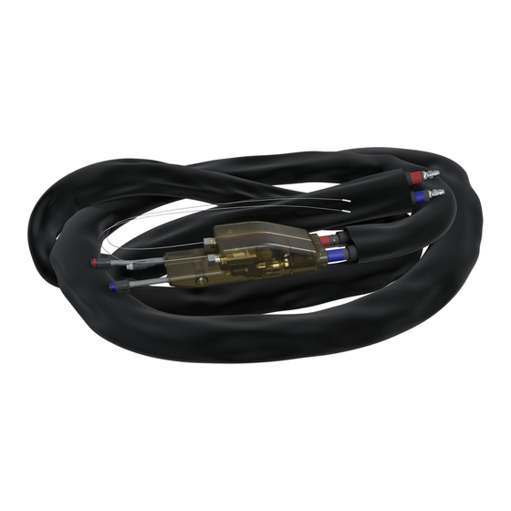
PRODUCT OVERVIEW QUICKHEAT HOSE - OVERVIEW ™ ™ QuickHeat Hoses are specifically designed to work with IntelliSpray™ proportioners. These hoses contain high-power internal electric heating cables, ensuring that all of the heating energy is transmitted directly to the fluid. ™ QuickHeat hoses are provided in: 50, 100, 150 or 200 foot (15, 30, 45, or 60m) lengths for master. -
Page 15: Technical Specifications
PRODUCT OVERVIEW QUICKHEAT HOSE - TECHNICAL SPECIFICATIONS ™ ITEM DETAILS Master hose: 50,100, 150, or 200ft length (15, 30, 45, or 60m) Mid hose: 100 or 150ft length (30 or 45m) Dimensions (Length) Smart-end: 20, 25 or 40ft length (6, 7 or 12m) Whip: 3, 4, 6, or 10ft length (1, 1.2, 2, 3m) Master and mid hoses has an internal diameter of 3/8”... -
Page 16: Quickheat Hose - Construction
PRODUCT OVERVIEW QUICKHEAT HOSE - CONSTRUCTION ™ HOSE COMPONENTS ™ The QuickHeat hose has the following components: Potted modem (2 halves per hose section) - Part of material hose assembly (non-removable) • Material Hoses (2 per hose section) - Replaceable •... - Page 17 PRODUCT OVERVIEW POTTED MODEM STRUCTURE Each hose segment has a potted modem half at the start of the segment (one hose section contains 2 modem halves). The modems may differ depending on whether they are part of a master, mid or smart-end segment. The differences are explained in the installation section of this manual.
-
Page 18: Quickheat Hose Set Configurations
PRODUCT OVERVIEW QUICKHEAT HOSE SET CONFIGURATIONS ™ The following figures show how Master, Mid, and Smart-End hose sections are assembled into 4 or 6 Zone sets. The only difference between a 4 and 6 zone set configuration is the presence of a Mid Hose with an integrated Y power splitter. -
Page 19: Configuration Connections - Power, Fluid And Communication
PRODUCT OVERVIEW CONFIGURATION CONNECTIONS - POWER, FLUID, AND COMMUNICATION 4-Zone Configuration 6-Zone Configuration A (Iso) Material Hose A (Iso) Hose Fluid Connector B (Res) Material Hose B (Res) Hose Fluid Connector Air Hose (for spray gun) Air Hose Connector A Hose Heat Power Cable (240V AC) A (Iso) Hose Power Connector B Hose Heat Power Cable (240V AC) B (Res) Hose Power Connector... -
Page 20: Installation
INSTALLATION INSTALLATION Refer to the IS30 and IS40 service manuals for instructions on hose setup, pairing modems and selecting communication frequency. ™ Before operating the QuickHeat Hose, ensure all the following installation steps have been completed. W A R NI N G You should only disconnect and reconnect hoses for maintenance or replacement procedures. -
Page 21: Proportioner To Hose Connections
INSTALLATION PROPORTIONER-TO-HOSE CONNECTIONS The first phase of the installation is connecting the master hose NOTE modem to the proportioner system. To achieve this: Prior to assembly uncoil hoses to remove any 1. Identify the Master Hose module through the serial number twists. - Page 22 INSTALLATION NOTE QuickHeat™ Hose assembly is compatible only with the IntelliSpray™ Systems. 5. Connect the jumper hose fittings (h) to the bottom modem inputs (i) and tighten using the Flats method (discussed in the “Flats Method” section of the manual). Remove plugs from the modem JIC fittings. 6.
-
Page 23: Hose To Hose Connections
INSTALLATION HOSE TO HOSE CONNECTIONS W A R N I N G Ensure that the system is powered down before continuing. Allowing fittings (A&B) to touch while the system is energized (SELV 24vdc) will cause a fault condition that will require a system reboot. Bridging fittings with a metal tool will also generate the same fault . - Page 24 INSTALLATION 8. Connect the power cables from the master hose to their matching cables in the mid modem (Refer to the “Cable Termination” section of this manual). See diagram below for layout and connection points. 9. Insert both assembled cables from modem into the center hole of the of the centering clamp, and reinstall bolts. Tighten clamp around cables with a 3mm Allen wrench.
- Page 25 INSTALLATION NOTE The Mid hose sections come with temp probe sheaths installed on the modem fluid fittings, to protect the probes from damage. You need to remove those in order to install any mid to a master segment. Keep the temperature probe sheaths, caps and plugs in case it is ever necessary to seal that section separately.
-
Page 26: Hose To Gun Connections
Hose is specially designed for use with the Carlisle ST1™ Air Purge Spray Gun. If you need to use other equipment, we recommend using only Carlisle approved Spray Guns or guns designed solely for the same purpose. www.carlisleft.com 341164 D (01/2024) -
Page 27: Operation
OPERATION HOSE USAGE KEY OPERATIONAL REQUIREMENTS All air must be purged from system before use to avoid system malfunction (pressure imbalance errors, chemical • solidification, hot spots in hose). Do not heat hose without fluid to avoid damaging the hose and causing leaks. •... -
Page 28: Troubleshooting
TROUBLESHOOTING PRODUCT TROUBLESHOOTING If these steps don’t solve your issue, please contact foam technical support at 651.925.4856 Issue Identification ActionResolution Leak between hose A or B material leaking out Power down the system. Trace down source of leak. Start by sections at JIC fitting of jacket or loss of opening jacket 3ft (1m) before and after joint to determine... - Page 29 TROUBLESHOOTING Issue Identification Resolution No air pressure Insufficient flow at gun or Inspect hose. Open section near modem (on the downstream audible air leak side of the joint). Inspect swivel fitting. Reconnect or tighten fitting as required. A cut air hose can be spliced with a 1/4in barb to barb fitting.
-
Page 30: Maintenance
MAINTENANCE PRODUCT MAINTENANCE W A R N I N G Shut off power and depressurize system before servicing. REGULAR MAINTENANCE PROCEDURES AND RECOMMENDATIONS Continuous use or lack of use of the system may both lead to system malfunctioning. Please conduct regular inspections to the system according to the frequency table below. -
Page 31: Spare Parts & Repair Kits
MAINTENANCE SPARE PARTS & REPAIR KITS Part Number Description 340970 KIT MODEM JACKET 340971 6' 1/4" INSULATED WHIP 341295 10' 1/4" INSULATED WHIP 340972 3/8" 20' SMART END w/ OPTICAL 341296 3/8" 40' SMART END w/ OPTICAL 340974 3/8" 100' MASTER - 6 ZONE SYS 340976 3/8"... - Page 32 MAINTENANCE SPARE PARTS & REPAIR KITS CONTINUED Part Number Description 341068 150' BLACK SCUFF JACKET 347431 HOSE CLAMP ASSEMBLY -SE 347432 SUPPLY AB JUMPER HOSE KIT 347433 MODEM BOLT (SHCS 3/8-16 X 1.5) 347434 3/8" 200' MASTER - 6 ZONE SYS 347439 3' 1/4 INSULATED WHIP 347515...
- Page 33 MAINTENANCE SPARE PARTS & REPAIR KITS CONTINUED Part Number Description 347564 5/16" 25' HIGHLY FLEXIBLE SMART END B 347565 5/16" 25' HIGHLY FLEXIBLE SMART END 347690 4' HIGHLY FLEXIBLE WHIP HOSE 347691 5/16" CLAMP ASSEMBLY 347692 50' MASTER AIR HOSE ASSY 347693 CABLE ASSY, 50FT A - MASTER 347694...
-
Page 34: Hose Section/Segment Replacement
MAINTENANCE HOSE SECTION/SEGMENT REPLACEMENT The following procedure is only needed in the case a hose section/segment needs to be replaced due to maintenance procedures or damage. Please refrain from disconnecting and reconnecting the hose section/segments unless required. Hose structure varies depending on the configuration of the system and the process is different whether connecting a Master, Mid or Smart End hose. - Page 35 MAINTENANCE SINGLE HOSE SEGMENT - REINSTALLATION 1. Position the new hose segment next to the other material hose within the hose section. 2. Reconnect the fluid fittings and tighten using the “Flats Method” discussed later in this manual. 3. Make any necessary power cable connections (only if power cables had been disconnected). See the “Cable Termination”...
-
Page 36: Wrapping New Hose Sections
MAINTENANCE WRAPPING NEW HOSE SECTIONS After completing the hose section replacement, wrap the hose section at the fittings and modem. Hose jacket should be re-installed around entire hose length with coated side out. Make sure the Velcro along the hose jacket is fully secured. If the jacket is excessively worn, replace jacket section. -
Page 37: Clamp Location Mapping
MAINTENANCE CLAMP LOCATION MAPPING It is very important to place the clamps in the locations specified in the diagram below. If clamps need to be removed for maintenance, re-install according to the diagram below. This protects electrical connections from upstream and downstream cable tension caused by pulling and bending the hose. -
Page 38: Cable Termination Section
MAINTENANCE CABLE TERMINATION SECTION 3. Install conductors (with ferrules installed) into main 1. Remove one side connector housing and nut from the connector body, and tighten screws using screwdriver connector in need of termination. (e). (Fig. 7,8). NOTE 2. Slide (1) connector nut, (1) sealing gasket, and (1) housing onto cable that is needing to be connected as Install conductors completely into housing seen in Fig. - Page 39 MAINTENANCE 4. Screw connector housing to connector body and Match cables per side tighten until housing bottoms out. (Fig. 9). Fig. 11 6. If necessary, repeat steps 1-6 for other end of connector. Fig. 9 NOTE Make sure A cable (red heat shrink/tape) is 5.
- Page 40 MANUAL REVISIONS MANUAL CHANGE SUMMARY Date Changes Version 17 Feb 22 1st draft, initial release Revision A 10 Oct 22 2nd draft Revision B 1 Aug 23 3rd draft Revision C 1 Jan 24 4th draft, updated template, pictures, installation & maintenance sections Revision D www.carlisleft.com 341164 D (01/2024)
- Page 41 MANUAL REVISIONS Page intentionally left blank. www.carlisleft.com 341164 D (01/2024)
- Page 42 WARRANTY POLICY This product is covered by Carlisle Fluid Technologies materials and workmanship limited warranty. The use of any parts or accessories, from a source other than Carlisle Fluid Technologies, will void all warranties. Failure to reasonably follow any maintenance guidance provided, may invalidate any warranty.
Need help?
Do you have a question about the QuickHeat Hose and is the answer not in the manual?
Questions and answers