Table of Contents
Advertisement
Quick Links
Reference Manual
Bulletin 1606 Switched Mode Power Supplies
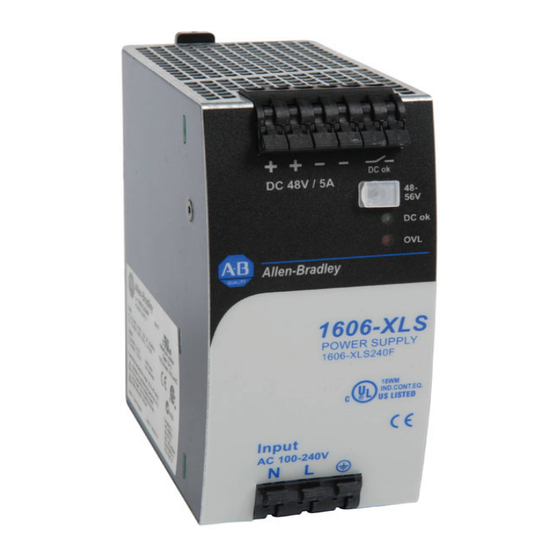
Catalog Numbers: 1606-XLS240F & 1606-XLS240F-D
Index
1. Intended Use .......................................................3
2. Installation Requirements ...................................3
3. AC-Input ...............................................................4
4. DC-Input ...............................................................5
5. Input Inrush Current ...........................................6
6. Output .................................................................7
7. Hold-up Time .......................................................9
8. DC-OK Relay Contact ..........................................9
9. Efficiency and Power Losses ..............................10
10. Reliability ...........................................................11
11. Functional Diagram ...........................................12
12. Terminals and Wiring ........................................12
13. Front Side and User Elements ...........................13
14. EMC ....................................................................14
15. Environment ......................................................15
16. Protection Features ...........................................16
17. Safety Features ..................................................16
18. Dielectric Strength ............................................16
19. Certifications .....................................................17
20. Environmental Compliance ..............................18
21. Physical Dimensions and Weight ......................18
Terminology and Abbreviations
• PE and
symbol-PE is the abbreviation for Protective Earth and has the same meaning as the symbol
• Earth, Ground-This document uses the term "earth" which is the same as the U.S. term "ground".
• T.b.d.-To be defined, value or description will follow later.
• 3AC 400V-A figure displayed with the AC or DC before the value represents a nominal voltage with standard tolerances (usually ±15%)
included. E.g.: DC 12V describes a 12V battery whether it is charged (13.7V) or discharged (10V).
• 230Vac-Afigure with the unit (Vac) at the end is a momentary figure without any additional tolerance included.
• 50Hz vs. 60Hz-Unless otherwise stated, AC 230V parameters are valid at 50Hz mains frequency.
• may-A key word indicating flexibility of choice with no implied preference.
• shall-A key word indicating a mandatory requirement.
• should-A key word indicating flexibility of choice with a strongly preferred implementation.
P
a
g
e
22. Accessories ........................................................ 19
22.2. 1606-XLSBUFFER48 Module ....................20
22.3. 1606-XLSRED Redundancy Module .............20
23. Application Notes ............................................. 21
23.1. Repetitive Pulse Loading ..........................21
23.2. Peak Current Capability ...........................22
23.3. Back-feeding Loads ..................................22
23.4. External Input Protection .........................22
23.6. Output Circuit Breakers ............................23
23.8. Parallel Use for Redundancy ....................24
23.9. Daisy Chaining of Outputs .......................25
23.10. Series Operation .......................................25
23.11. Inductive and Capacitive Loads ................25
23.12. Operation on Two Phases ........................26
23.13. Use in a Tightly Sealed Enclosure ............26
23.14. Mounting Orientations ............................27
P
a
g
e
.......19
...............................23
.
Advertisement
Table of Contents

Subscribe to Our Youtube Channel
Related Manuals for Allen-Bradley 1606-XLS240F


Summary of Contents for Allen-Bradley 1606-XLS240F
-
Page 1: Table Of Contents
Reference Manual Bulletin 1606 Switched Mode Power Supplies Catalog Numbers: 1606-XLS240F & 1606-XLS240F-D Index 1. Intended Use ............3 22. Accessories ............19 2. Installation Requirements ........3 22.1. 1606-XLB Wall Mounting Bracket ..19 3. AC-Input ...............4 22.2. 1606-XLSBUFFER48 Module ....20 4. DC-Input ...............5 22.3. - Page 2 Catalog Numbers Certification Marks 1606-XLS240F Power Supply 48-56V Power supply 1606-XLS240F-D Extended DC Input IND. CONT. EQ.
-
Page 3: Intended Use
Bulletin 1606 Switched Mode Power Supplies Intended Use • This device is designed for installation in an enclosure and is intended for the general professional use such as in industrial control, office, communication, and instrumentation equipment. • Do not use this power supply in aircraft, trains, nuclear equipment or similar systems where malfunction may cause severe personal injury or threaten human life. -
Page 4: Ac-Input
Bulletin 1606 Switched Mode Power Supplies 3. AC-Input AC input nom. AC 100-240V suitable for TN-, TT- and IT mains networks AC input range min. 85-276Vac continuous operation min. 60-85Vac full power for 200ms, no damage between 0 and 85Vac min. -
Page 5: Dc-Input
Bulletin 1606 Switched Mode Power Supplies 4. DC-Input 1606-XLS240F: DC input nom. DC 110-150V -20%/+25% DC input range min. 88-187Vdc continuous operation DC input current typ. 2.37A 110Vdc, at 24V, 10A 1606-XLS240F-D: DC input nom. DC 110-300V -20%/+25% DC input range min. -
Page 6: Input Inrush Current
Bulletin 1606 Switched Mode Power Supplies 5. Input Inrush Current An active inrush limitation circuit limits the input inrush current after turn-on of the input voltage and after short input voltage interruptions. The charging current into EMI suppression capacitors is disregarded in the first microseconds after switch-on. AC 100V AC 120V AC 230V... -
Page 7: Output
Bulletin 1606 Switched Mode Power Supplies 6. Output Output voltage nom. Adjustment range min. 48-56V guaranteed ***) max. at clockwise end position of potentiometer Factory setting typ. 48.0V ±0.2%, at full load, cold unit Line regulation max. 10mV 60-300Vac Load regulation max. - Page 8 Bulletin 1606 Switched Mode Power Supplies Fig. 6-1 Output voltage vs. output current, Fig. 6-2 Bonus time vs. output power typ. Output Voltage Adjustment Bonus Time Range Output Current Output Power 160% Fig. 6-3 BonusPower recovery time Limitation by Power Power Manager Demand 100%...
-
Page 9: Hold-Up Time
Bulletin 1606 Switched Mode Power Supplies 7. Hold-up Time AC 100V AC 120V AC 230V Hold-up Time typ. 51ms 53ms 55ms at 48V, 2.5A, see Fig. 7-1 typ. 26ms 27ms 28ms at 48V, 5A, see Fig. 7-1 Fig. 7-1 Hold-up time vs. input voltage Fig. -
Page 10: Efficiency And Power Losses
Bulletin 1606 Switched Mode Power Supplies 9. Efficiency and Power Losses AC 100V AC 120V AC 230V Efficiency typ. 90.4% 91.2% 92.0% at 48V, 5A Average efficiency *) typ. 89.6% 90.0% 90.3% 25% at 1.25A, 25% at 2.5A, 25% at 3.75A, 25% at 5A Power losses typ. -
Page 11: Reliability
Bulletin 1606 Switched Mode Power Supplies 10. Reliability AC 100V AC 120V AC 230V Lifetime expectancy 57 000h 67 000h 81 000h at 48V, 5A and 40°C 118 000h 112 000h 118 000h at 48V, 2.5A and 40°C 161 000h*) 188 000h*) 228 000h*) at 48V, 5A and 25°C... -
Page 12: Functional Diagram
Bulletin 1606 Switched Mode Power Supplies 11. Functional Diagram Fig. 11-1 Functional diagram Output Voltage Regulator Input Fuse Input Filter Output Power Input Rectifier Filter Converter Converter Active Transient Filter & Inrush Current Limiter Overload DC-ok Temper- Output Output Output ature Over- Power... -
Page 13: Front Side And User Elements
Bulletin 1606 Switched Mode Power Supplies 13. Front Side and User Elements Fig. 13-1 Front side Input Terminals (Quick-connect spring-clamp terminals) N, L Line input PE (Protective Earth) input B Output Terminals (Quick-connect spring-clamp terminals, two pins per pole) Positive output –... -
Page 14: Emc
Bulletin 1606 Switched Mode Power Supplies 14. EMC The power supply is suitable for applications in industrial environment as well as in residential, commercial and light industry environment without any restrictions. The CE Mark indicates conformance with the EMC directive 2004/108/EC, the low-voltage directive (LVD) 2006/95/EC and the RoHS directive 2011/65/EC. -
Page 15: Environment
Bulletin 1606 Switched Mode Power Supplies Switching Frequencies The power supply has three converters with three different switching frequencies included. Two are nearly constant. The other one is input voltage and load dependent. Switching frequency 1 35kHz nearly constant Switching frequency 2 105kHz nearly constant Switching frequency 3... -
Page 16: Protection Features
Bulletin 1606 Switched Mode Power Supplies 16. Protection Features Output protection Electronically protected against overload, no-load and short-circuits Output over-voltage protection typ. 58Vdc In case of an internal power supply defect, a redundant max. 60Vdc circuit limits the maximum output voltage. The output shuts down and automatically attempts to restart. -
Page 17: Certifications
Bulletin 1606 Switched Mode Power Supplies 19. Certifications EC Declaration of Conformity Complies with CE EMC and CE Low Voltage Directives. UL 508 LISTED E56639 for use in the U.S.A. (UL 508) and Canada (C22.2 No. 14-95) IND. CONT. EQ. Industrial Control Equipment UL 60950-1 RECOGNIZED for use in the U.S.A. -
Page 18: Environmental Compliance
Bulletin 1606 Switched Mode Power Supplies 20. Environmental Compliance The unit does not release any silicone and is suitable for use in paint shops. The unit conforms to the RoHS directives 2002/95/EC and 2011/65/EC. Electrolytic capacitors included in this unit do not use electrolytes such as Quaternary Ammonium Salt Systems. Plastic housings and other molded plastic materials are free of halogens, wires and cables are not PVC insulated. -
Page 19: Accessories
Bulletin 1606 Switched Mode Power Supplies 22. Accessories 22.1. 1606-XLB Wall Mounting Bracket This bracket is used to mount the power supply onto a flat surface without a DIN rail. All parameters are specified at 48V, 5A, 230Vac, 25°C ambient and after a 5 minutes run-in time, unless noted otherwise. Rockwell Automation Publication 1606-RM045A-EN-P —... -
Page 20: 1606-Xlsbuffer48 Module
Bulletin 1606 Switched Mode Power Supplies 22.2. 1606-XLSBUFFER48 Buffer Module This buffer unit is a supplementary device for DC 48V power supplies. It delivers power to bridge typical mains failures or extends the hold-up time after turn-off Power Buffer of the AC power. In times when the pow Load Supply Unit(s) -
Page 21: Application Notes
Bulletin 1606 Switched Mode Power Supplies 23. Application Notes 23.1. Repetitive Pulse Loading Typically, a load current is not constant and varies over time. This power supply is designed to support loads with a higher short-term power demand (=BonusPower). The short-term duration is hardware-controlled by an output power manager and is available on a repeated basis. -
Page 22: Peak Current Capability
Bulletin 1606 Switched Mode Power Supplies 23.2. Peak Current Capability Solenoids, contactors and pneumatic modules often have a steady state coil and a pick-up coil. The inrush current demand of the pick-up coil is several times higher than the steady-state current and usually exceeds the nominal output current (including the PowerBoost). -
Page 23: Charging Batteries
Bulletin 1606 Switched Mode Power Supplies 23.5. Charging Batteries The power supply can be used to charge lead-acid or maintenance free batteries. (Four 12V batteries in series) Instructions for charging batteries: Set output voltage (measured at no load and at the battery end of the cable) very precisely to the end-of-charge voltage. -
Page 24: Parallel Use To Increase Output Power
Bulletin 1606 Switched Mode Power Supplies 23.7. Parallel Use to Increase Output Power Unit A Power supplies from the same series (XLS) can be paralleled to increase the output power. The output voltage shall be adjusted to the same value (±100mV) with the same load conditions on all units, or the units can be left with the factory settings. -
Page 25: Daisy Chaining Of Outputs
Bulletin 1606 Switched Mode Power Supplies 23.9. Daisy Chaining of Outputs Daisy chaining (jumping from one power supply output to the next) is allowed as long as the average output current through one terminal pin does not exceed 25A. If the current is higher, use a separate distribution terminal block as shown in Fig. -
Page 26: Operation On Two Phases
Bulletin 1606 Switched Mode Power Supplies 23.12. Operation on Two Phases Power Supply The power supply can also be used on two phases of a three-phase-system. Such a phase-to-phase connection is allowed as long as the supplying internal fuse voltage is below 240V+15%. Use a fuse or a circuit breaker to protect the N input. -
Page 27: Mounting Orientations
Bulletin 1606 Switched Mode Power Supplies 23.14. Mounting Orientations Mounting orientations other than input terminals on the bottom and output on the top require a reduction in continuous output power or a limitation in the maximum allowed ambient temperature. The amount of reduction influences the lifetime expectancy of the power supply. - Page 28 Rockwell Automation Support Rockwell Automation provides technical information on the Web to assist you in using its products. At http://www.rockwellautomation.com/support, you can find technical manuals, technical and application notes, sample code and links to software service packs, and a MySupport feature that you can customize to make the best use of these tools.
Need help?
Do you have a question about the 1606-XLS240F and is the answer not in the manual?
Questions and answers