Advertisement
Table of Contents
- 1 Battery Installation
- 2 Connect Power and Equipment to the Ups
- 3 Operation
- 4 Display Panel Indicators and Function Buttons
- 5 User Configurable Items
- 6 Ups Settings
- 7 Replacing the Battery Module
- 8 Troubleshooting
- 9 Safety Information
- 10 Handling Safety
- 11 Replacement and Recycling of Batteries
- Download this manual
See also:
User Manual
Advertisement
Table of Contents

Summary of Contents for Allen-Bradley 1609
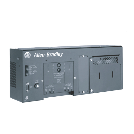
- Page 1 1609 Industrial Uninterruptible Power Supply User Manual Installation and Operation 41063-222-01 (1) 990-1868 12/2004...
-
Page 2: Battery Installation
Mount the UPS This unit is designed to mount on a heavy duty DIN rail or on the back panel of an enclosure. For details on DIN rail installation refer to the DIN rail installation guide included in the DIN rail package. The DIN rail kit is not included. -
Page 3: Connect Power And Equipment To The Ups
In 230 V applications the UPS must be protected with a circuit breaker that complies with European standards for branch rated protection per the country of installation. – In 208 V applications, the 1609-U500E must be protected by a dual pole, 10 A branch rated circuit breaker with UL489 rating. –... - Page 4 Connectors Communication Port SERIAL PORT Contact Closure Port 8 NO 7 COM BATTERY 6 NC 5 NO 4 COM BATTERY 3 NC 2 EPO COM 1 EPO Output Contact Ratings: nominal switching capacity maximum switching power maximum switching voltage maximum switching current maximum carrying current surge ratings Emergency Power Off...
-
Page 5: Operation
Operation Operation UPS Display Panel 120 V models Test INPUT 208/220-240V~ 50/60Hz, 7A MAX GROUND NEUTRAL LINE Display Panel Indicators and Function Buttons Indicator Indicator Title On-Line AVR Trim AVR Boost On Battery Overload Replace Battery/Battery Disconnected 208/230 V models OUTPUT 0V~ 50/60Hz, 500VA 325W, 2.7A MAX... - Page 6 Diagnostic Utility Voltage Battery Charge Feature Feature Title Button Power On Power Off Self-Test Cold Start The UPS has a diagnostic feature that indicates the utility voltage. The UPS starts a self-test as part of this procedure. The self-test does not affect the voltage display.
-
Page 7: User Configurable Items
User Configurable Items User Configurable Items UPS settings Settings are adjusted through PowerChute software or optional Network Management Card. Factory Function Default Automatic Every 14 days Self-Test (336 hours) UPS ID UPS_IDEN Date of Last Manufacture Battery Date Replacement Minimum Capacity 0 percent Before Return from Shutdown... - Page 8 • 100 VAC • 106 VAC can tolerate this condition. The 1609-U500E ships ready for 230 V • 196 VAC • 204 VAC sources. When operating the UPS in 208 V • 200 VAC •...
-
Page 9: Replacing The Battery Module
Ensure battery replacement every 2-4 years. Standard (40C) battery; Allen-Bradley catalog number: 1609-500SBAT. High Temperature (50C) battery; Allen-Bradley catalog number: 1609-500HBAT. Once the batteries are disconnected the connected equipment is not protected from power outages. Refer to the appropriate replacement battery installation guide for battery module installation instructions. See your dealer or contact Rockwell Automation at 440-646-5800 for information on replacement battery modules. -
Page 10: Troubleshooting
Troubleshooting Use this chart to solve minor installation and operation problems. Refer to Rockwell Automation Tech Support at 440-646-5800 for further support. Problem and/or Possible Cause UPS will not turn on The battery is not connected properly. button not pushed. The UPS is not connected to utility power supply. - Page 11 Troubleshooting Problem and/or Possible Cause All LEDs are off and the UPS is wired to input utility power The UPS is shut down or the battery is discharged from an extended outage. The Overload LED is illuminated and the UPS emits a sustained alarm tone The UPS is overloaded.
- Page 12 Problem and/or Possible Cause There is no utility power There is no utility power and the UPS is UPS operates on battery although line voltage exists The UPS input circuit breaker trips. Your system is experiencing very high, low or distorted line voltage. Battery Charge and Load LEDs flash simultaneously The UPS has shut down The internal temperature of the UPS has...
- Page 13 Service and Contact Information Service and Contact Information Service If the UPS requires service do not return it to the dealer. Follow these steps: 1. Review the problems discussed in Troubleshooting to eliminate common problems. 2. If the problem persists, contact Rockwell Automation Customer Support. –...
-
Page 14: Safety Information
Safety Information - This Safety Guide contains important instructions that should be followed during installation and maintenance of the equipment and batteries. It is intended for customers who setup, install, relocate, or maintain equipment. Changes and modifications to this unit not expressly approved could void the warranty. Handling Safety <18 kg (<40 lb) 18–32 kg (40–70 lb)


Need help?
Do you have a question about the 1609 and is the answer not in the manual?
Questions and answers