Table of Contents
Advertisement
Quick Links
Reference Manual
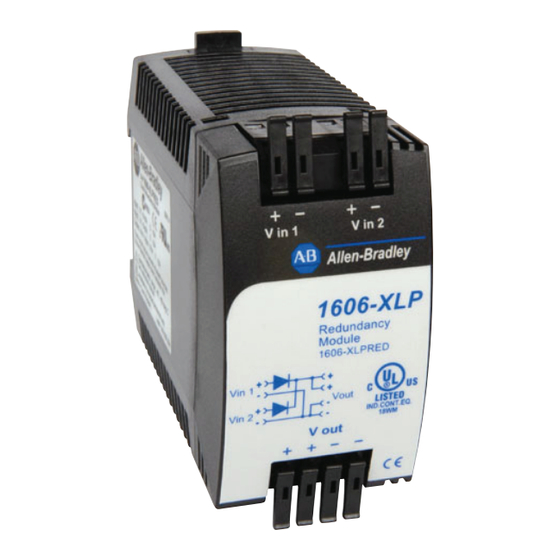
Bulletin 1606 Switched Mode Power Supplies
Catalog Number: 1606-XLSPRED
Index
1. Intended Use .......................................................3
2. Installation Requirements...................................3
3. Input and Output Characteristics .......................4
4. Power Losses........................................................5
5. Lifetime Expectancy and MTBF...........................6
6. Terminals and Wiring..........................................7
7. Functional Diagram.............................................8
8. Front Side and User Elements.............................8
9. EMC......................................................................9
10. Environment ......................................................10
11. Protection Features ...........................................11
12. Safety Features ..................................................11
Terminology and Abbreviations
PE and
symbol
Earth, Ground
T.b.d.
DC 24V
24Vdc
may
shall
should
1+1 Redundancy
N+1 Redundancy
Allen-Bradley HMIs
P
a
g
PE is the abbreviation for Protective Earth and has the same meaning as the symbol
This document uses the term "earth" which is the same as the U.S. term "ground".
To be defined, value or description will follow later.
A figure displayed with the AC or DC before the value represents a nominal voltage with
standard tolerances (usually ±15%) included.
E.g.: DC 12V describes a 12V battery disregarding whether it is full (13.7V) or flat (10V)
A figure with the unit (Vdc) at the end is a momentary figure without any additional
tolerances included.
A key word indicating flexibility of choice with no implied preference
A key word indicating a mandatory requirement
A key word indicating flexibility of choice with a strongly preferred implementation
Use of two identical power supplies in parallel to provide continued operation following most
failures in a single power supply. The two
power supply outputs should be isolated
from each other by utilizing diodes or
other switching arrangements.
E.g. two 2.5A power supplies are needed to
achieve a 2.5A redundant system.
Use of three or more identical power
supplies in parallel to provide continued
operation following most failures in a
single power supply. All power supply
outputs should be isolated from each other
by utilizing diodes or other switching
arrangements. E.g.: To achieve a 10A redundant system, five 2.5A power supplies are needed in
a N+1 redundant system.
e
13. Certifications .................................................... 12
14. Physical Dimensions and Weight ..................... 13
15. Accessories ........................................................ 13
16. Application Notes ............................................. 14
16.1. Recommendations for Redundancy .........14
16.2. Inductive and Capacitive Loads ................14
16.3. Example: 1+1 Redundancy .......................14
16.4. Example: N+1 Redundancy .......................15
16.5. Example: Battery Back-up ........................15
16.6. Mounting Orientations ............................16
AC
AC
DC
DC
IN 1
IN 2
OUT
N+1
Redundancy
AC
AC
AC
AC
DC
DC
DC
DC
IN 1
IN 2
IN 1
IN 2
OUT
OUT
-
Load
P
a
g
e
.
1+1
Redundancy
AC
AC
DC
DC
IN 1
IN 2
OUT
-
Load
Advertisement
Table of Contents

Related Manuals for Allen-Bradley 1606-XLPRED


Summary of Contents for Allen-Bradley 1606-XLPRED
-
Page 1: Table Of Contents
All power supply outputs should be isolated from each other Load Load by utilizing diodes or other switching arrangements. E.g.: To achieve a 10A redundant system, five 2.5A power supplies are needed in a N+1 redundant system. Allen-Bradley HMIs... - Page 2 3 Year Warranty Description Specification Quick Reference ±25% DC 12-48V w/o restrictions The 1606-XLPRED is a simple redundancy module that Input voltage ±25% DC 12-120V with restrictions you can use to build 1+1 and N+1 redundant systems. It is equipped with two input channels, which can be...
-
Page 3: Intended Use
• The unit is suitable for use in Class I Division 2 Groups A, B, C, D locations Allen-Bradley HMIs All parameters are specified at 24V, 2.5A, 230Vac input, 25ªC ambient and after a 5 minutes run-in time unless noted otherwise. -
Page 4: Input And Output Characteristics
Bulletin 1606 Switched Mode Power Supplies 3. Input and Output Characteristics Number of inputs Number of outputs ±25% Input voltage nom. DC 12-48V The input circuitry must meet the SELV requirements stipulated by IEC/EN/UL 60950-1. Input voltage range 9–60Vdc Input voltage with restrictions nom. -
Page 5: Power Losses
Fig. 3-2 Input to output voltage drop when both inputs draw current (typical 1+1 redundant case, when the output voltages of the two units are equal or set into “parallel use” mode) Voltage Drop, typ. Output Variable 1606-XLPRED Load, 1000mV 24V,5A 0-10A... -
Page 6: Lifetime Expectancy And Mtbf
Bulletin 1606 Switched Mode Power Supplies 5. Lifetime Expectancy and MTBF The redundancy module has two input channels which are completely independent from each other. Each control circuit, auxiliary voltage source, or other circuitry in the module is designed separately for each input. The dual input redundancy module can be considered as two single redundancy modules combined together in one housing. -
Page 7: Terminals And Wiring
Do not connect or disconnect the wires from the terminals below -25°C (-13°F). Allen-Bradley HMIs All parameters are specified at 24V, 2.5A, 230Vac input, 25ªC ambient and after a 5 minutes run-in time unless noted otherwise. Rockwell Automation Publication 1606-RM035A-EN-P — April 2014... -
Page 8: Functional Diagram
Bulletin 1606 Switched Mode Power Supplies 7. Functional Diagram Fig. 7-1 Functional diagram Input 1 Output Input 2 8. Front Side and User Elements Fig. 8-1 Front side Output terminals B Input terminals for input 1 C Input terminals for input 2 All parameters are specified at 24V, 2.5A, 230Vac input, 25ªC ambient and after a 5 minutes run-in time unless noted otherwise. -
Page 9: Emc
Provided, that power sources connected on the inputs fulfill the class B requirements as well. Allen-Bradley HMIs All parameters are specified at 24V, 2.5A, 230Vac input, 25ªC ambient and after a 5 minutes run-in time unless noted otherwise. -
Page 10: Environment
Bulletin 1606 Switched Mode Power Supplies 10. Environment Operational temperature -40°C to +70°C (-40°F to 158°F) Reduce output power above +60°C Output de-rating 0.25A/°C 60-70°C (140°F to 158°F), see Storage temperature -40 to +85°C (-40°F to 185°F) for storage and transportation Humidity 5 to 95% r.H. -
Page 11: Protection Features
PELV source. Class of protection plastic housing, PE connection not required Allen-Bradley HMIs All parameters are specified at 24V, 2.5A, 230Vac input, 25ªC ambient and after a 5 minutes run-in time unless noted otherwise. Rockwell Automation Publication 1606-RM035A-EN-P — April 2014... -
Page 12: Certifications
Bulletin 1606 Switched Mode Power Supplies 13. Certifications EN 60950-1, EN 61204-3 Complies with - CE EMC directive - CE Low-Voltage Directive The CE mark indicates conformance with the - ATEX directive 94/9/EC (Equipment and protection systems intended for use in potentially explosive atmospheres) UL 508 LISTED E56639 for use in the U.S.A. -
Page 13: Physical Dimensions And Weight
A suitable DIN rail bracket is available upon request. The picture of the power supply is for representation only. Allen-Bradley HMIs All parameters are specified at 24V, 2.5A, 230Vac input, 25ªC ambient and after a 5 minutes run-in time unless noted otherwise. -
Page 14: Application Notes
Bulletin 1606 Switched Mode Power Supplies 16. Application Notes 16.1. Recommendations for Redundancy Recommendations for the configuration of redundant power systems: • Use separate input fuses for each power supply. • Use three-phase power supplies to gain functional safety if one phase fails. •... -
Page 15: Example: N+1 Redundancy
Set output voltage of power supply to 26.5Vdc minimum to ensure that the load current is delivered from the power supply and not from the charger (battery). Use a fuse between the battery and the 1606-XLPRED module! Fig. 16-3 Wiring diagram, 10A Battery back-up... -
Page 16: Mounting Orientations
Bulletin 1606 Switched Mode Power Supplies 16.6. Mounting Orientations Mounting orientations other than input terminals on the bottom and output on the top require a reduction in continuous output power or a limitation in the maximum allowed ambient temperature. Fig. 16-4 Output Current Mounting INPUT... - Page 17 Allen-Bradley HMIs...
- Page 18 Rockwell Automation Support Rockwell Automation provides technical information on the Web to assist you in using its products. At http://www.rockwellautomation.com/support, you can find technical manuals, technical and application notes, sample code and links to software service packs, and a MySupport feature that you can customize to make the best use of these tools.
Need help?
Do you have a question about the 1606-XLPRED and is the answer not in the manual?
Questions and answers