
Related Manuals for Allen-Bradley 1606-XLE480FP-D


Summary of Contents for Allen-Bradley 1606-XLE480FP-D
- Page 1 Switched Mode Power Supply Catalog Number 1606-XLE480FP-D Reference Manual Original Instructions...
- Page 2 Switched Mode Power Supply Reference Manual Important User Information Read this document and the documents listed in the additional resources section about installation, configuration, and operation of this equipment before you install, configure, operate, or maintain this product. Users are required to familiarize themselves with installation and wiring instructions in addition to requirements of all applicable codes, laws, and standards.
-
Page 3: Table Of Contents
Table of Contents Terminology and Abbreviations ........3 Product Overview . - Page 4 Table of Contents Notes: Rockwell Automation Publication 1606-RM047A-EN-P - September 2021...
-
Page 5: Terminology And Abbreviations
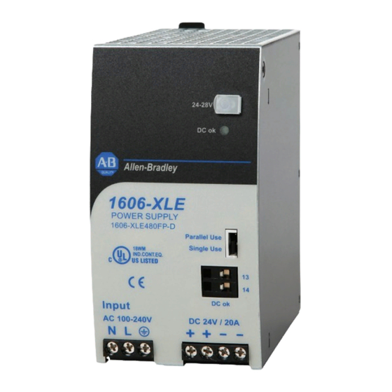
25 °C (77 °F) ambient temperature • After a 5 minutes run-in time Product Overview Figure 1 - 1606-XLE480FP-D The 1606-XLE480FP-D is a cost- optimized power supply unit and DC/DC converter. Features of these units include a wide DC-input range, electronic inrush current limitation, and a wide operational temperature range. -
Page 6: Specifications
W x H x D (2.56 x 4.88 x 5 in.) Weight 940 g (2.1 lb) — Catalog Numbers Cat. No. Descriptions DC/DC converter 1606-XLE480FP-D (48…56V standard unit) 1606-XLC Wall mount bracket 1606-XLA-S63 Side mount bracket 1606-XLSRED40HF Redundancy module AC Input Do not operate this DC/DC converter with AC-input voltage. - Page 7 Values Attributes Notes DC 110V DC 300V Input voltage DC 110…300V — 88…360V DC — Short term, with output derating (1%/V), or with Input voltage range 88…100V DC reduced ambient temperature, see Figure 19 on page 13, no damage between 0…88V DC 360…425V DC Short term, <500 ms 360V DC...
-
Page 8: Input Inrush Current
Input Inrush Current An active inrush limitation circuit limits the input inrush current after turn-on of the input voltage and after short input voltage interruptions. The charging current into EMI suppression capacitors is disregarded in the first microseconds after switch-on. Values Attributes Notes... - Page 9 PLUS Figure 9 - Dynamic Overcurrent Capability, Typ Figure 8 - Short-circuit on Output, Hiccup Mode, Typ Output Voltage (Dynamic Behavior, <15 ms) 56 V Output Current Normal Normal Short-circuit Operation Operation Adjustment Range 20 A 18 s 18 s 18 s Output Current 50 A...
-
Page 10: Hold-Up Time
Hold-up Time A diode to the input voltage isolates the internal capacitor that supplies the energy for the hold-up time. A short on the input line does not discharge the internal hold-up capacitor. Values Attributes Notes DC 110V DC 300V 65 ms 65 ms At 48V, 5 A, see... -
Page 11: Efficiency And Power Losses
Efficiency and Power Losses Values Attributes Notes AC 110V AC 300 93.1% 94.6% At 48V, 10 A Efficiency 93.1% 94.5% At 48V, 12 A (Power Boost) 92.1% 93.3% 25% at 2.5 A, 25% at 5 A, 25% at 7.5 A, 25% at 10 A Average efficiency 7.4 W 2.5 W... -
Page 12: Functional Diagram
Functional Diagram Figure 17 - Functional Diagram Input Fuse Input Filter Output Power Boost Active Inrush Limiter Filter Converter Converter Reverse Polarity Protection Single / Output Parallel Voltage Regulator Output Output Temperature Power Overvoltage Shut- DC-OK Manager Protection down Output Voltage DC-OK DC-OK... -
Page 13: Terminals And Wiring
Terminals and Wiring The terminals are IP20 fingersafe constructed and suitable for field and factory wiring. Values Attributes Input and Output DC-OK Signal Type Screw termination Spring clamp terminals Solid wire 0.5…6 mm 0.15…1.5 mm Stranded wire 0.5…4 mm 0.15…1.5 mm American Wire Gauge 20…10 AWG 26…14 AWG... -
Page 14: Mean Time Between Failure (Mtbf)
Mean Time Between Failure MTBF is calculated according to statistical device failures, and indicates the reliability of a device. It is the statistical representation of the likelihood of a (MTBF) unit to fail; it does not necessarily represent the life of a product. An MTBF value of, for example, 1,000,000 hr means that statistically one unit fails every 100 hours if 10,000 units are installed in the field. -
Page 15: Environment
Environment Attributes Values Notes -25…+70 °C (-13…+158 °F) Reduce output power according to Figure 19 Operational temperature Storage temperature -40…+85 °C (-40…+185 °F) For storage and transportation 6.4 W/1 °C (6.4 W/1.8 °F) Between 45…60 °C (113…140 °F) Output derating 12 W/1 °C (12 W/1.8 °F) Between 60…70 °C (140…158 °F) 5…95% r.H. -
Page 16: Safety Features
(2) For use in a controlled environment according to CSA 22.2 No 107.1-01. Safety Features Attributes Values Notes SELV IEC/EN 60950-1 Input/output separation PELV IEC/EN 60204-1, EN 50178, IEC 62103, IEC 60364-4-41 Class of protection PE connection required. Isolation resistance >5 MΩ... -
Page 17: Certifications And Standards Compliance
Certifications and Standards Compliance Names Symbols Notes UL Certificate Listed equipment for category NMTR - Industrial Control UL 508 Equipment Applicable for US (UL 508) and Canada (C22.2 No. 107-1-01) IND. CONT. EQ. E-File: E198865 UL Certificate Recognized component for category QQGQ - Information Technology Equipment UL 60950-1 Level 5... -
Page 18: Accessories
Figure 22 - Front View [mm (in.)] Figure 23 - Side View [mm (in.)] 19.1 25.4 Width 127 (5.0) (0.12) (0.75) (0.12) DIN Rail Depth Width 65 (2.56) Accessories 1606-XLC Wall Mounting Bracket This bracket is used to mount the DC/DC converter onto a flat surface without using a DIN rail. - Page 19 DIN rail. Figure 29 - Typical 1+1 Redundant Configuration for 48V, 10 A Figure 28 - Redundancy Module with a Dual Redundancy Module Failure 10 A Monitor Load 1606-XLE480FP-D 1606-XLE480FP-D 48…56V 480 W 48…56V 480 W DC/DC DC/DC Output Converter...
-
Page 20: Peak Current Capability
Peak Current Capability The DC/DC converter can deliver peak currents (up to several milliseconds) which are higher than the specified short-term currents. Peak current capability helps to start current-demanding loads. Solenoids, contactors, and pneumatic modules often have a steady state coil and a pickup coil. -
Page 21: Inductive And Capacitive Loads
Inductive and Capacitive The unit is designed to supply any kind of loads, including unlimited capacitive and inductive loads. If extreme large capacitors, such as EDLCs Loads (electric double layer capacitors or UltraCaps) with a capacitance of >0.15F are PLUS connected to the output, the unit can charge the capacitor in the Hiccup mode (see Output on page... -
Page 22: External Input Protection
A minimum value of 10 A B- or C-characteristic breaker must be used. Parallel Use to Increase 1606-XLE480FP-D DC/DC converters can be paralleled to increase the output power. The output voltage must be adjusted to the same value (±100 mV) in Output Power Single Use mode with the same load conditions on all units, or the units can be left with the factory settings. -
Page 23: Parallel Use For Redundancy
Set the unit into Parallel Use mode. • Monitor the individual units. Use the DC-OK relay contact of the 1606-XLE480FP-D DC/DC converter. • Set the output voltages of all units to the same value (±100 mV) or leave output voltages at the factory setting. -
Page 24: Series Operation
Figure 34 - Daisy Chain of Outputs Figure 35 - Using Distribution Terminals Distribution Terminals Power Power Power Power Supply Supply Supply Supply Load Load Output Output Output Output 54 A Series Operation Figure 36 - Series Operation DC/DC converters of the same type can be connected in series for Unit A higher output voltages. -
Page 25: Mounting Orientations
Attributes Values 254 x 180 x 165 mm (4.88 x 7.09 x 6.50 in.) Enclosure size Rittal Typ IP66 Box PK 9522 100, plastic Input voltage 300V DC Load 48V, 8 A; (=80%) Temperature inside enclosure 50.3 °C (122.54 °F) Temperature outside enclosure 24.2 °C (75.56 °F) Temperature rise... - Page 26 Output Current 12 A Figure 39 - Mounting Orientation C: Table-top Mounting Ambient Temperature 60 °C Output Current 12 A Figure 40 - Mounting Orientation D: Horizontal CW Ambient Temperature 60 °C Output Current 12 A Figure 41 - Mounting Orientation E: Horizontal CCW Ambient Temperature 60 °C...
-
Page 27: Additional Resources
Automation products in a secure system, harden the control system, manage user access, and dispose of equipment. Industrial Components Preventive Maintenance, Enclosures, and Contact Provides a quick reference tool for Allen-Bradley industrial automation controls and Ratings Specifications, publication IC-TD002 assemblies. - Page 28 At the end of life, this equipment should be collected separately from any unsorted municipal waste. Rockwell Automation maintains current product environmental compliance information on its website at rok.auto/pec. Allen-Bradley, expanding human possibility, and Rockwell Automation are trademarks of Rockwell Automation, Inc. Trademarks not belonging to Rockwell Automation are property of their respective companies.
Need help?
Do you have a question about the 1606-XLE480FP-D and is the answer not in the manual?
Questions and answers