
Related Manuals for Allen-Bradley 1769-PA2


Summary of Contents for Allen-Bradley 1769-PA2
-
Page 1: Table Of Contents
Installation Instructions Original Instructions Compact I/O Expansion Power Supplies Catalog Numbers 1769-PA2, 1769-PB2, 1769-PA4, 1769-PB4 Topic Page Summary of Changes About the Power Supplies Before You Begin Assemble the System Mount an I/O Expansion Power Supply Verify Your System Power... -
Page 2: Topic
Compact I/O Expansion Power Supplies Summary of Changes This publication contains new and updated information as indicated in this table. Topic Page Updated to current template and format Throughout Updated document with current Attention, Tip, and Warning statements Throughout Updated document with current specifications and certifications Throughout Rockwell Automation Publication 1769-IN028C-EN-P - August 2016... - Page 3 Compact I/O Expansion Power Supplies Rockwell Automation Publication 1769-IN028C-EN-P - August 2016...
-
Page 4: North American Hazardous Location Approval
Compact I/O Expansion Power Supplies North American Hazardous Location Approval The following information applies when operating Informations sur l’utilisation de cet équipement en this equipment in hazardous locations. environnements dangereux. Les produits marqués "CL I, DIV 2, GP A, B, C, D" ne conviennent Products marked "CL I, DIV 2, GP A, B, C, D"... - Page 5 Compact I/O Expansion Power Supplies Environment and Enclosure ATTENTION: This equipment is intended for use in a Pollution Degree 2 industrial environment, in overvoltage Category II applications (as defined in EN/IEC 60664-1), at altitudes up to 2000 m (6562 ft) without derating. This equipment is not intended for use in residential environments and may not provide adequate protection to radio communication services in such environments.
-
Page 6: European Hazardous Location Approval
Compact I/O Expansion Power Supplies Always hard-wire circuits that are installed on the machine for safety reasons directly to the master control relay. Examples include overtravel limit switches, stop push buttons, and interlocks. These devices must be wired in series so that when any one device opens, the master control relay is de-energized, which removes power from the machine. -
Page 7: About The Power Supplies
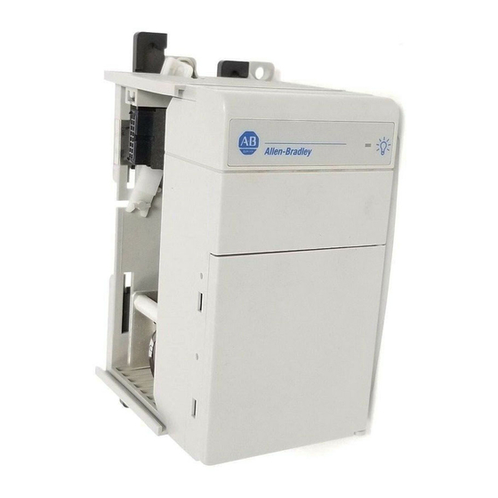
Compact I/O Expansion Power Supplies ATTENTION: This equipment is not resistant to sunlight or other sources of UV radiation. About the Power Supplies Compact I/O™ power supplies provide 120/240V AC and 24V DC power to modules, which you can place to the left or the right side of the 1769 power supply. As many as eight I/O modules can be placed on each side of the power supply. - Page 8 Compact I/O Expansion Power Supplies Parts Illustration of a Power Supply The sample illustrations of a 1769-PA4 power supply let you review the various components that comprise a power supply, which is attached to a DIN rail. 1769-PA4 Power Supply Components Item Description Bus lever (with locking function)
- Page 9 Compact I/O Expansion Power Supplies Power Supply Components (Continued) Item Description Nameplate label Upper tongue-and-groove slots Lower tongue-and-groove slots Upper DIN rail latches Lower DIN rail latches Terminal block with fingersafe cover Fuse housing cover for replaceable fuse 120V AC or 240V AC line input power selector switch (PA4 only) Removable selector switch label (PA4 only) Install an I/O Expansion Power Supply Compact I/O Expansion Power Supplies are suitable for use in an industrial environment when...
-
Page 10: Assemble The System
1769 Compact I/O power supplies distribute power from either side of the power supply. EXAMPLE A 2 amp at 5V DC power supply (1769-PA2, 1769-PB2) can provide 1 amp to the right side of the power supply and 1 amp to the left. A 4 amp at 5V DC power supply (1769-PA4 and 1769-PB4) can provide 2 amps to the right side of the power supply and 2 amps to the left. - Page 11 Compact I/O Expansion Power Supplies Follow these steps to assemble the Compact I/O system. 1. Disconnect your line power. The power supply does not support removal or insertion of modules under power. WARNING: If you connect or disconnect wiring while the field-side power is on, an electrical arc can occur.
-
Page 12: Mount An I/O Expansion Power Supply
Compact I/O Expansion Power Supplies Mount an I/O Expansion Power Supply ATTENTION: During panel or DIN rail mounting of all devices, be sure that all debris (for example, metal chips, wire strands) is kept from falling into the module. Debris that falls into the module could cause damage on power up. - Page 13 Additional grounding connections from the power supply's mounting tabs or DIN rail (if used) are not required unless the mounting surface cannot be grounded. Refer to Industrial Automation Wiring and Grounding Guidelines, Allen-Bradley publication 1770-4.1, for additional information.
-
Page 14: Verify Your System Power
Compact I/O Expansion Power Supplies 2. Press the DIN rail mounting area of the module against the DIN rail. The latches momentarily open and lock into place. The following illustration shows a power supply being attached to the I/O modules in a DIN rail mounted Compact I/O system. -
Page 15: Power Considerations
Compact I/O Expansion Power Supplies • Total 24V DC sensor power (1769-PA2 only) 3. If your power supply load is at or above the limits of the allowable ranges that are shown in the graphs, you must add an additional I/O bank. - Page 16 Reload the user program following a power supply shutdown. ATTENTION: To avoid unexpected operation due to 24V DC user power shutdown (1769-PA2 only), monitor the 24V DC user output with a 24V DC input channel.
-
Page 17: Use A Master Control Relay
Compact I/O Expansion Power Supplies Use a Master Control Relay A hard-wired master control relay (MCR) provides a reliable means for emergency machine shutdown. Since the master control relay allows the placement of several emergency stop switches in different locations, its installation is important from a safety standpoint. Overtravel limit switches or mushroom-head push buttons are wired in series so that when any of them opens, the master control relay is de-energized. -
Page 18: Schematic (Using Iec Symbols)
Compact I/O Expansion Power Supplies Schematic (Using IEC Symbols) 230V AC Operation of either of these contacts removes power from the external Disconnect I/O circuits, which stops machine motion. Fuse 230V AC Circuits Isolation Master Control Relay (MCR) Transformer Cat. No. 700-PK400A1 115V AC Suppressor Start... -
Page 19: Schematic (Using Ansi/Csa Symbols)
Compact I/O Expansion Power Supplies Schematic (Using ANSI/CSA Symbols) Operation of either of these contacts 230V AC removes power from the external I/O circuits, which stops machine motion. Disconnect Fuse 230V AC Circuits Isolation Transformer Master Control Relay (MCR) Cat. No. 700-PK400A1 Emergency-Stop Push 115V AC Suppressor... - Page 20 Compact I/O Expansion Power Supplies Power Supply Connection Bank 1 Bank 2 Item Description 1, 2 The maximum amount of bus current that can be distributed on the 1769 bus (on either side of the power supply, A or B) is: •...
-
Page 21: Connect Field Wires
Additional grounding connections from the power supply's mounting tabs or DIN rail (if used) are not required unless the mounting surface cannot be grounded. Refer to Industrial Automation Wiring and Grounding Guidelines, Allen-Bradley publication 1770-4.1, for additional information. - Page 22 NOT USED NOT USED +24V DC +24V DC DC NEUTRAL DC NEUTRAL CHASSIS GROUND CHASSIS GROUND Catalog Number 1769-PA2 Catalog Number 1769-PA4 *PWR OUT +24V DC NOT USED NOT USED *PWR OUT COM 120/240V AC (L1) 120/240V AC (L1) V AC COM (L2)
- Page 23 Compact I/O Expansion Power Supplies Wire the Fingersafe Terminal Block When wiring the terminal block, keep the fingersafe cover in place. 1. Loosen the terminal screws to be wired. Wiring the Fingersafe Terminal Block 2. Route the wire under the terminal pressure plate. You can use the bare wire or a spade lug.
-
Page 24: Replace The Fuse
Compact I/O Expansion Power Supplies Replace the Fuse ATTENTION: Never install, remove, or wire power supplies unless power has been switched off. Follow these steps to replace a blown fuse. 1. Remove Compact I/O system power to correct conditions that are causing the short circuit. -
Page 25: Temperature Derating
Compact I/O Expansion Power Supplies Temperature Derating The following graphs indicate how much current can be drawn from the power supply at the indicated case temperature without damaging it. 1769-PA2 Output Derating With User +24V Current Draw at 0 Amps 0.875 55 °C 60 °C... - Page 26 Compact I/O Expansion Power Supplies With User +24V Current Draw at 0.25 Amps 55 °C +24V Bus Load (Amps) Rockwell Automation Publication 1769-IN028C-EN-P - August 2016...
- Page 27 Compact I/O Expansion Power Supplies 1769-PB2 Output Derating Total Output: 29 W at 60 °C (140 °F) or below 60 °C +24V Bus Load (Amps) 1769-PA4 Output Derating Total Output: 68 W at 55 °C (131 °F) or below 61 W at 60 °C (140 °F) or below 55 °C 60 °C +24V Bus Load (Amps)
- Page 28 Compact I/O Expansion Power Supplies 1769-PB4 Output Derating Total Output: 61 W at 60 °C (140 °F) or below 60 °C +24V Bus Load (Amps) Rockwell Automation Publication 1769-IN028C-EN-P - August 2016...
-
Page 29: Power Dissipation
Compact I/O Expansion Power Supplies Power Dissipation The following graphs indicate the real electrical power dissipation of the power supply in function of the electrical load. 1769-PA2 Real Power Dissipation 55 °C 60 °C Bus +5V, +24V, and User +24V Load... - Page 30 Compact I/O Expansion Power Supplies 1769-PA4 Real Power Dissipation 60 °C 55 °C Bus +5V, +24V, and User +24V Load (Watts) 1769-PB4 Real Power Dissipation 55 °C 60 °C Bus +5V, +24V, and User +24V Load (Watts) Rockwell Automation Publication 1769-IN028C-EN-P - August 2016...
-
Page 31: Specifications
Compact I/O Expansion Power Supplies Specifications Technical Specifications Attribute 1769-PA2 1769-PB2 1769-PA4 1769-PB4 Input voltage range 85…265V AC 19.2…31.2V DC 85…132V AC or 19.2…32V DC 170…265V AC, switch selectable Input frequency range 47…63 Hz 47…63 Hz Power supply distance rating... -
Page 32: Environmental Specifications
Compact I/O Expansion Power Supplies Environmental Specifications Attribute 1769-PA2 1769-PB2 1769-PA4 1769-PB4 Temperature, operating 0…60 °C (32…140 °F) IEC 60068-2-1 (Test Ad, Operating Cold IEC 60068-2-2 (Test Bd, Operating Dry Heat) IEC 60068-2-14 (Test Nb, Operating Thermal Shock) Temperature, -40…+85 °C (-40…+185 °F) - Page 33 IEC 61000-4-29 Certifications Certifications 1769-PA2, 1769-PA4 1769-PB2, 1769-PB4 c-UL-us UL Listed for Class 1, Division 2 Group A,B,C,D Hazardous Locations, certified for U.S. and Canada. See UL File E10314 European Union 2014/30/EU EMC Directive, compliant European Union 2014/30/EU EMC Directive, compliant...
-
Page 34: Additional Resources
Compact I/O Expansion Power Supplies Certifications Compability with MicroLogix 1500 To use the 1769 expansion I/O power supply with the MicroLogix 1500 processor, the processor (catalog number 1764-LSP or 1764-LRP) must be series A, revision C, Firmware Revision Number (FRN) 3 or later. Look at the processor nameplate to check the firmware revision. Status file bit S:59 (Operating System Firmware Revision Number) If your processor is at an older revision, you must upgrade the operating system. - Page 35 Compact I/O Expansion Power Supplies Notes: Rockwell Automation Publication 1769-IN028C-EN-P - August 2016...
- Page 36 Rockwell Automation maintains current product environmental information on its website at http://www.rockwellautomation.com/rockwellautomation/about-us/sustainability-ethics/product-environmental-compliance.page. Allen-Bradley, Compact I/O, CompactLogix, MicroLogix, Rockwell Automation, and Rockwell Software are trademarks of Rockwell Automation, Inc. Trademarks not belonging to Rockwell Automation are property of their respective companies.
Need help?
Do you have a question about the 1769-PA2 and is the answer not in the manual?
Questions and answers