Table of Contents
Advertisement
Quick Links
Reference Manual
Bulletin 1606 Switched Mode Power Supplies
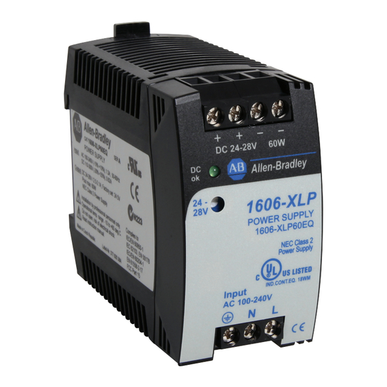
Catalog Number: 1606-XLP60EQT
Index
1. Intended Use .......................................................3
2. Installation Requirements...................................3
3. AC-Input...............................................................4
4. Input Inrush Current ...........................................5
5. Output .................................................................6
6. Hold-up Time.......................................................7
7. DC-Input...............................................................7
8. Efficiency and Power Losses................................8
9. Functional Diagram.............................................9
10. Front Side and User Elements.............................9
11. Terminals and Wiring........................................10
12. Lifetime Expectancy and MTBF.........................10
13. EMC....................................................................11
14. Environment ......................................................12
15. Protection Features ...........................................13
16. Safety Features ..................................................13
17. Dielectric Strength ............................................14
18. Certifications .....................................................15
19. Physical Dimensions and Weight......................16
Terminology and Abbreviations
• PE and
symbol-PE is the abbreviation for Protective Earth and has the same meaning as the symbol
• Earth, Ground-This document uses the term "earth" which is the same as the U.S. term "ground".
• T.b.d.-To be defined, value or description will follow later.
• AC 230V-A figure displayed with the AC or DC before the value represents a nominal voltage with standard tolerances (usually ±15%)
included. E.g.: DC 12V describes a 12V battery, whether it is full (13.7V) or flat (10V)
• 230Vac-A figure with the unit (Vac) at the end is a momentary figure without any additional tolerances included.
• 50Hz vs. 60Hz-As long as not otherwise stated, AC 100V and AC 230V parameters are valid at 50Hz mains frequency and 120V parameters
are valid at 60Hz mains frequency.
• may-A key word indicating flexibility of choice with no implied preference.
• shall-A key word indicating a mandatory requirement.
• should-A key word indicating flexibility of choice with a strongly preferred implementation.
a P
g
e
20. Accessory........................................................... 17
20.1. 1606-XLSBUFFER24 Module........................17
21. Application Notes............................................. 18
21.1. Peak Current Capability ...........................18
21.2. Back-feeding Loads ..................................18
21.4. External Input Protection.........................19
21.6. Daisy Chaining of Outputs .......................20
21.7. Inductive and Capacitive Loads................20
21.8. Series Operation .......................................21
21.9. Operation on Two Phases ........................21
21.10. Use Without PE on the Input ...................21
21.11. Use at Low Temperatures (-25°C / -40°C).22
21.12. Use in a Tightly Sealed Enclosure ............22
21.13. Mounting Orientations ............................23
a P
g
e
...............................19
.
Advertisement
Table of Contents

Related Manuals for Allen-Bradley Rockwell Automation 1606-XLP60EQT


Summary of Contents for Allen-Bradley Rockwell Automation 1606-XLP60EQT
-
Page 1: Table Of Contents
Reference Manual Bulletin 1606 Switched Mode Power Supplies Catalog Number: 1606-XLP60EQT Index 1. Intended Use ............3 20. Accessory............17 2. Installation Requirements........3 20.1. 1606-XLSBUFFER24 Module......17 3. AC-Input...............4 21. Application Notes..........18 4. Input Inrush Current ...........5 21.1. Peak Current Capability ......18 5. - Page 2 Bulletin 1606 Switched Mode Power Supplies Power Supply 100-240V Wide Range Input NEC Class 2 Compliant Adjustable Output Voltage Efficiency up to 90.4% Low No-load Losses and Excellent Partial-load Efficiency Compact Design, Width only 45mm Electronic Inrush Current Limitation Operation down to -40°C Full Output Power up to +60°C Large International Approval Package 3 Year Warranty...
-
Page 3: Intended Use
Bulletin 1606 Switched Mode Power Supplies 1. Intended Use • This device is designed for installation in an enclosure and is intended for the general professional use such as in industrial control, office, communication, and instrumentation equipment. • Do not use this power supply in equipment where malfunction may cause severe personal injury or threaten human life. 2. -
Page 4: Ac-Input
Bulletin 1606 Switched Mode Power Supplies 3. AC Input AC input nom. AC 100-240V -15% / +10%, TN/TT/IT-mains AC input range 85-264Vac continuous operation, reduce output power linearly to 50W between 90Vac and 85Vac at ambient temperatures above +45°C, see Fig. 3-5 264–300Vac <... -
Page 5: Input Inrush Current
Bulletin 1606 Switched Mode Power Supplies Fig. 3-5 De-rating requirements for low input voltages Allowable Output Power 85Vac 90Vac Input Voltage 4. Input Inrush Current An electronic inrush current circuit limits the input inrush current after turn-on of the input voltage. The inrush current is input voltage and ambient temperature independent. -
Page 6: Output
Bulletin 1606 Switched Mode Power Supplies 5. Output Output voltage nom. Adjustment range min. 24-28V guaranteed max. 30V *) at clockwise end position of potentiometer *) Factory setting 24.5V ±0.2%, at full load, cold unit Line regulation max. 10mV 85-264Vac Load regulation max. -
Page 7: Hold-Up Time
Bulletin 1606 Switched Mode Power Supplies 6. Hold-up Time AC 100V AC 120V AC 230V Hold-up Time typ. 36ms 54ms 218ms at 24V, 1.25A, see Fig. 6-1 typ. 15ms 24ms 107ms at 24V, 2.5A, see Fig. 6-1 Note: At no load, the hold-up time can be up to several seconds. The green DC-ok lamp is also on during this time Fig. -
Page 8: Efficiency And Power Losses
Bulletin 1606 Switched Mode Power Supplies 8. Efficiency and Power Losses AC 100V AC 120V AC 230V Efficiency typ. 87.4% 88.5% 90.4% at 24V, 2.5A (full load) Power losses typ. 0.45W 0.5W 0.85W at 0A typ. 3.9W 3.7W 3.9W at 24V, 1.25A (half load) typ. -
Page 9: Functional Diagram
Bulletin 1606 Switched Mode Power Supplies 9. Functional Diagram Fig. 9-1 Functional diagram Input Rectifier Input Fuse & Output & Power Filter Active Converter Input Filter Inrush Limiter Output Output Over- Voltage Voltage Protection Regulator 10. Front Side and User Elements Fig. -
Page 10: Terminals And Wiring
Bulletin 1606 Switched Mode Power Supplies 11. Terminals and Wiring All terminals are easy to access when mounted on the panel. Input and output terminals are separated from each other (input below, output above) to help in error-free wiring. Input Output Type screw terminals... -
Page 11: Emc
Bulletin 1606 Switched Mode Power Supplies 13. EMC The power supply is suitable for applications in industrial environment as well as in residential, commercial and light industry environment without any restrictions. A detailed EMC report is available upon request. EMC Immunity Generic standards: EN 61000-6-1 and EN 61000-6-2 Electrostatic discharge EN 61000-4-2... -
Page 12: Environment
Bulletin 1606 Switched Mode Power Supplies 14. Environment Operational temperature -40°C to +70°C (-40°F to 158°F) reduce output power according Fig. 14-1 Storage temperature -40°C to +85°C (-40°F to 185°F) for storage and transportation Output de-rating 1.5W/°C 60-70°C (140°F to 158°F) Humidity 5 to 95% r.H. -
Page 13: Protection Features
Bulletin 1606 Switched Mode Power Supplies 15. Protection Features Output protection Electronically protected against overload, no-load and short-circuits Output over-voltage protection typ. 31Vdc In case of an internal power supply fault, a redundant max. 32.5Vdc circuit limits the maximum output voltage. In such a case, the output shuts down and stays down until the input voltage is turned off and on again. -
Page 14: Dielectric Strength
Bulletin 1606 Switched Mode Power Supplies 17. Dielectric Strength The output voltage is floating and has no ohmic connection to the ground. Type and factory tests are conducted by the manufacturer. Field tests may be conducted in the field using the appropriate test equipment which applies the voltage with a slow ramp (2s up and 2s down). -
Page 15: Certifications
Bulletin 1606 Switched Mode Power Supplies 18. Certifications EC Declaration of Complies with Conformity - CE EMC directive - CE Low-voltage directive UL 508 Listed E56639 for use in the U.S.A. (UL 508) and Canada (C22-2 No. 19-45). Industrial Control Equipment UL 60950-1 RECOGNIZED E168663 for use in the U.S.A. -
Page 16: Physical Dimensions And Weight
Bulletin 1606 Switched Mode Power Supplies 19. Physical Dimensions and Weight Weight 250g / 0.55lb DIN Rail Use 35mm DIN rails according to EN 60715 or EN 50022 with a height of 7.5 or 15mm. The DIN rail height must be added to the unit depth (91mm) to calculate the total required installation depth. -
Page 17: Accessory
Bulletin 1606 Switched Mode Power Supplies 20. Accessory 20.1. 1606-XLSBUFFER24 Buffer Module This buffer unit is a supplementary device for DC 24V power supplies. It delivers power to bridge typical mains failures or extends the hold-up time after turn-off of the AC power. In times when the power supply provides sufficient voltages, the buffer module stores energy in integrated electrolytic capacitors. -
Page 18: Application Notes
Bulletin 1606 Switched Mode Power Supplies 21. Application Notes 21.1. Peak Current Capability Solenoids, contactors and pneumatic modules often have a steady state coil and a pick-up coil. The inrush current demand of the pick-up coil is several times higher than the steady-state current and usually exceeds the nominal output current. -
Page 19: Charging Batteries
Bulletin 1606 Switched Mode Power Supplies 21.3. Charging Batteries The power supply can be used to charge lead-acid or maintenance free batteries. (Two 12V batteries in series) Instructions for charging batteries (float charging): Ensure that the ambient temperature of the power supply is below 45°C Set output voltage (measured at no load and at the battery end of the cable) very precisely to the end-of-charge voltage. -
Page 20: Daisy Chaining Of Outputs
Bulletin 1606 Switched Mode Power Supplies 21.6. Daisy Chaining of Outputs Daisy chaining (jumping from one power supply output to the next) is allowed as long as the average output current through one terminal pin does not exceed 25A. If the current is higher, use a separate distribution terminal block. Fig. -
Page 21: Series Operation
Bulletin 1606 Switched Mode Power Supplies 21.8. Series Operation Unit A Power supplies of the exact same type can be connected in series for higher output voltages. It is possible to connect as many units in series as needed, providing the sum of the output voltage does not exceed 150Vdc. Voltages with a potential above 60Vdc are not SELV any more and can be dangerous. -
Page 22: Use At Low Temperatures (-25
Bulletin 1606 Switched Mode Power Supplies 21.11. Use at Low Temperatures (-25°C / -40°C) Please pay attention to the following aspects when operating the unit at low temperatures. Perform tests to verify suitability in your application. The ripple & noise voltage will increase. For the first minutes after turning on the unit at -40°C, the ripple an noise voltage can be up to typically 400mVpp depending on load and input voltage. -
Page 23: Mounting Orientations
Bulletin 1606 Switched Mode Power Supplies 21.13. Mounting Orientations Mounting orientations other than input terminals on the bottom and output on the top require a reduction in continuous output power or a limitation in the maximum allowed ambient temperature. The amount of reduction influences the lifetime expectancy of the power supply. - Page 24 Rockwell Automation Support Rockwell Automation provides technical information on the Web to assist you in using its products. At http://www.rockwellautomation.com/support, you can find technical manuals, technical and application notes, sample code and links to software service packs, and a MySupport feature that you can customize to make the best use of these tools.
Need help?
Do you have a question about the Rockwell Automation 1606-XLP60EQT and is the answer not in the manual?
Questions and answers