Advertisement
Installation Instructions
Original Instructions
ControlLogix Power Supply
Catalog Numbers 1756-PA30XT, 1756-PA50, 1756-PA72, 1756-PA75, 1756-PB30XT, 1756-PB50, 1756-PB72, 1756-PB75, 1756-PC75, 1756-PH75,
1756-PAXT, 1756-PBXT
Topic
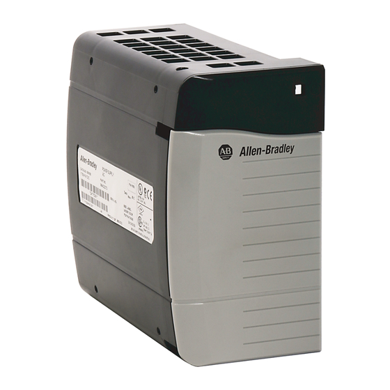
Product Overview
ControlLogix® power supplies are used with the 1756 chassis to provide 1.2V, 3.3V, 5V, and 24V DC power directly to the chassis backplane.
Standard, ControlLogix-XT™, and slim (reduced width) power supplies are available.
Page
5
6
7
7
9
9
10
11
Advertisement

Related Manuals for Allen-Bradley 1756-PA30XT


Summary of Contents for Allen-Bradley 1756-PA30XT
-
Page 1: Table Of Contents
Installation Instructions Original Instructions ControlLogix Power Supply Catalog Numbers 1756-PA30XT, 1756-PA50, 1756-PA72, 1756-PA75, 1756-PB30XT, 1756-PB50, 1756-PB72, 1756-PB75, 1756-PC75, 1756-PH75, 1756-PAXT, 1756-PBXT Topic Page Tools Required Power Supply and Chassis Compatibility Install the Power Supply Connect the Power Remove the Protective Label... - Page 2 ControlLogix Power Supply ATTENTION: Read this document and the documents listed in the Additional Resources section about installation, configuration and operation of this equipment before you install, configure, operate or maintain this product. Users are required to familiarize themselves with installation and wiring instructions in addition to requirements of all applicable codes, laws, and standards. Activities including installation, adjustments, putting into service, use, assembly, disassembly, and maintenance are required to be carried out by suitably trained personnel in accordance with applicable code of practice.
- Page 3 This equipment is certified for use only within surrounding air temperature range of 0…60 °C (32…140 °F) [1756-PA72, 1756-PA75, 1756-PB72, 1756-PB75, 1756-PC75, 1756-PH75, 1756-PA50, 1756-PB50] or -25…+70 °C (-13…+158 °F) [1756-PAXT, 1756-PBXT, 1756-PA30XT, 1756-PB30XT]. The equipment must not be used outside its range.
- Page 4 ControlLogix Power Supply ATTENTION: If this equipment is used in a manner not specified by the manufacturer, the protection provided by the equipment may be impaired. North American Hazardous Location Approval The following information applies when operating this equipment in Informations sur l'utilisation de cet équipement en environnements hazardous locations: dangereux:...
-
Page 5: Tools Required
— 1756-PAXT None — — 1756-PBXT Ex nA IIC T4 Gc DEMKO13ATEX1325026X IECEx UL 14.0008X 1756-PA30XT None — — 1756-PB30XT Ex nA IIC T4 Gc DEMKO13ATEX1325026X IECEx UL 14.0008X WARNING: Removable Terminal Blocks When you connect or disconnect the Removable Terminal Block (RTB) with field side power applied, an electrical arc can occur. This could cause an explosion in hazardous location installations. -
Page 6: Power Supply And Chassis Compatibility
1756-A4/A, 1756-A7/A, 1756-A10/A, 1756-A13/A, 1756-A17/A, 1756-A4/B, 1756-A7/B, 1756-A10/B, 1756-A13/B, 1756-A17/B, 1756-A4/C, 1756-A7/C, 1756-A10/C, 1756-A13/C, 1756-A17/C 1756-PB72/C 1756-PA50 1756-PB50 1756-PA75/B 1756-A4/B, 1756-A7/B, 1756-A10/B, 1756-A13/B, 1756-A17/B, 1756-A4/C, 1756-A7/C, 1756-A10/C, 1756-A13/C, 1756-A17/C 1756-PB75/B 1756-PC75/B 1756-PH75/B 1756-PBXT 1756-A4LXT/B, 1756-A5XT/B, 1756-A7LXT/B, 1756-A7XT/B, 1756-A7XT/C 1756-PAXT 1756-PA30XT 1756-PB30XT Rockwell Automation Publication 1756-IN619A-EN-P - April 2016... -
Page 7: Install The Power Supply
ControlLogix Power Supply Install the Power Supply 1. Make sure that the chassis is installed and grounded correctly. 2. Align the power-supply circuit board with the card guides on the left side of the chassis. 3. Slide the power supply back until it is flush with the front of the chassis. Card Guide 4. - Page 8 2.5 mm² (14 AWG) 75 °C (167 °F) copper wire with 1.2 mm (3/64-in.) insulation Optional Power Cable Connection The 1756-PA50, 1756-PB50, 1756-PA30XT, and 1756-PB30XT power supplies offer an optional cable retention mechanism. Install the optional cable retention mechanism per the following procedure.
-
Page 9: Remove The Protective Label
ControlLogix Power Supply Remove the Protective Label ATTENTION: Make sure the chassis is mounted and all panel fabrication is complete before you remove the protective label. This label protects the power supply from metal shavings falling inside the power supply and damaging it during operation. Remove the protective label from the top of the power supply. -
Page 10: Specifications
ControlLogix Power Supply c. Reinstall the power supply in the chassis. d. Turn on the power. • Remains OFF: Contact your local Allen-Bradley distributor. Specifications 1756-PB72, 1756-PB75, Attribute 1756-PA72 1756-PA75 1756-PC75 1756-PH75 1756-PB72K 1756-PB75K Voltage and current ratings Input: 120/240V... -
Page 11: Additional Resources
Provides declarations of conformity, certificates, and other certification details. certification/overview.page You can view or download publications at http://www.rockwellautomation.com/literature/. To order paper copies of technical documentation, contact your local Allen-Bradley distributor or Rockwell Automation sales representative. Rockwell Automation Publication 1756-IN619A-EN-P - April 2016... - Page 12 Rockwell Automation maintains current product environmental information on its website at http://www.rockwellautomation.com/rockwellautomation/about-us/sustainability-ethics/product-environmental-compliance.page. Allen-Bradley, ControlLogix, ControlLogix-XT, Rockwell Automation, and Rockwell Software are trademarks of Rockwell Automation, Inc. Trademarks not belonging to Rockwell Automation are property of their respective companies. Rockwell Otomasyon Ticaret A.Ş., Kar Plaza İş Merkezi E Blok Kat:6 34752 İçerenköy, İstanbul, Tel: +90 (216) 5698400...
Need help?
Do you have a question about the 1756-PA30XT and is the answer not in the manual?
Questions and answers