
Related Manuals for Allen-Bradley 1606-XLB480E


Summary of Contents for Allen-Bradley 1606-XLB480E
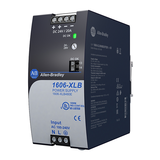
- Page 1 Basic Power Supply - 24V, 20 A, 480 W, Single-phase Input Catalog Number 1606-XLB480E Reference Manual Original Instructions...
- Page 2 Basic Power Supply - 24V, 20 A, 480 W, Single-phase Input Reference Manual Important User Information Read this document and the documents listed in the additional resources section about installation, configuration, and operation of this equipment before you install, configure, operate, or maintain this product. Users are required to familiarize themselves with installation and wiring instructions in addition to requirements of all applicable codes, laws, and standards.
-
Page 3: Table Of Contents
Table of Contents Terminology and Abbreviations ........5 Product Overview . - Page 4 Table of Contents Notes: Rockwell Automation Publication 1606-RM104A-EN-P - July 2020...
-
Page 5: Terminology And Abbreviations
Terminology and Term, Abbreviation, Definition Abbreviations or Symbol PE is the abbreviation for Protective Earth and has the same meaning as the symbol in the following row. The symbol for Protective Earth. This symbol has the same meaning as PE. Earth, Ground This document uses the term ‘earth’... -
Page 6: Specifications
— (2.32 x 4.88 x 5.00 in.) Weight 810 g (1.97 lb) — Catalog Numbers Catalog Numbers Descriptions 1606-XLB480E Industrial grade power supply 1606-XLSBUFFER24 Buffer module 1606-XLSRED4HE Dual redundancy module 1606-XLBRED20 Dual redundancy module Rockwell Automation Publication 1606-RM104A-EN-P - July 2020... -
Page 7: Ac Input
AC Input The device is suitable to be supplied from TN, TT, or IT mains networks with AC voltage. Attributes Values Notes AC input AC 100…240V — 90…264V AC Continuous operation AC input range 264…300V AC Occasionally for 500 ms max Allowed voltage L or N to earth 300V AC Continuous, according to IEC 60664-1... -
Page 8: Input Inrush Current
Input Inrush Current An active inrush limitation circuit (NTCs, which are bypassed by a relay contact) limits the input inrush current after turn-on of the input voltage. The charging current into EMI suppression capacitors is disregarded in the first microseconds after switch-on. Values Attributes Notes... -
Page 9: Output
Output The output provides a SELV/PELV rated voltage, which is galvanically isolated from the input voltage. The output is designed to supply any kind of loads, including capacitive and inductive loads. If capacitors with a capacitance > 3 F are connected to the output, the unit might charge the capacitor in an intermittent mode. -
Page 10: Hold-Up Time
Hold-up Time The hold-up time is the time during which output voltage of a power supply remains within specification following the loss of input power. The hold-up time is output load dependent. At no load, the hold-up time can be up to several seconds. -
Page 11: Efficiency And Power Losses
Efficiency and Power Values Losses Attributes Notes AC 100V AC 120V AC 230V Efficiency 93.6% 94.2% 95.3% At 24V, 20 A Average 25% at 5 A, 25% at 10 A, 93.4% 93.8% 94.5% 25% at 15 A, 25% at 20 A efficiency 5.7 W 4.6 W... -
Page 12: Functional Diagram
Functional Diagram Figure 16 - Functional diagram Input Fuse Input Filter Output Power Filter Converter Input Rectifier Converter Inrush Current Limiter DC-ok DC OK Relay Contact DC OK Status Indicator Temper- Output ature Over- Output Shut- Voltage Voltage down Protection Regulator Front Side and User Figure 17 - Front side... -
Page 13: Connection Terminals
Connection Terminals The terminals are IP20 fingersafe constructed and suitable for field- and factory wiring. Attributes Input Output DC OK-Signal Type Screw termination Screw termination Push-in termination Solid wire 6 mm max (0.0093 in max) 6 mm max (0.0093 in max) 1.5 mm max (0.0023 in... -
Page 14: Electromagnetic Compatibility
Electromagnetic The EMC behavior of the device is designed for applications in industrial, residential, commercial, and light-industrial environments. Compatibility The device complies with EN 61000-6-1, EN 61000-6-2, EN 61000-6-3, EN 61000-6-4, EN 61000-3-2, and EN 61000-3-3. Without additional measures to reduce the conducted emissions on the output (for example by using a filter), the device is not suited to supply a local DC power network in industrial, residential, commercial, and light-industrial environments. -
Page 15: Environment
Switching Frequencies PFC converter 80...130 kHz Input voltage and load dependent Main converter 75...180 kHz Output voltage and load dependent Auxiliary converter 60 kHz Fixed frequency Environment Attributes Values Notes Operational temperature is the same as the ambient or surrounding Operational temperature -25…+70 °C (-13…+158 °F) temperature and is defined as the air temperature 2 cm (0.79 in.) -
Page 16: Safety And Protection Features
Safety and Protection Features Attributes Values Notes 500 MOhm At delivered condition between input and output, measured with 500V DC 500 MOhm At delivered condition between input and PE, measured with 500V DC Isolation resistance 500 MOhm At delivered condition between output and PE, measured with 500V DC 500 MOhm At delivered condition between output and DC OK contacts, measured with 500V DC PE resistance... -
Page 17: Dielectric Strength
Dielectric Strength The output voltage is floating and has no ohmic connection to the ground. The output is insulated to the input by a double or reinforced insulation. The manufacturer constructs type and routine tests. Field tests may be conducted in the field using the appropriate test equipment, which applies the voltage with a slow ramp (2 s up and 2 s down). -
Page 18: Approvals And Fulfilled Standards
Approvals and Fulfilled Approval Name Approval Symbol Notes Standards CB Scheme Certificate IEC 61010 IEC 61010-2-201 Electrical Equipment for Measurement, Control, and (planned) Laboratory Use - Particular requirements for control equipment CB Scheme Certificate IEC 62368-1 Audio/video, information, and communication IEC 62368 technology equipment - Safety requirements Output safety level: ES1... -
Page 19: Physical Dimensions And Weight
Physical Dimensions and Attributes Descriptions Weight Width 59 mm (2.32 in.) Height 124 mm (4.88 in.) 127 mm (5.0 in.) The DIN rail height must be added to the unit depth to calculate the Depth total required installation depth. Weight 810 g (1.79 lb) Use 35 mm (1.38 in.) DIN rails according to EN 60715 or EN 50022 with a height of 7.5 or DIN rail... -
Page 20: Accessories
Accessories This section describes accessories that can be used with the power supply. 1606-XLSRED4HE Redundancy Module The 1606-XLSRED4HE is a dual redundancy module, which can be used to build 1+1 or N+1 redundant systems. The device is equipped with two 20 A nominal input channels, which are individually decoupled by using MOSFET technology. -
Page 21: 1606-Xlsbuffer24 Buffer Module
1606-XLSBUFFER24 Buffer Module The 1606-XLSBUFFER24 buffer module is a supplementary device for DC 24V power supplies. It delivers power to bridge typical mains failures or extends the hold-up time after the AC power is turned off. When the power supply provides a sufficient voltage, the buffer module stores energy in the integrated electrolytic capacitors. -
Page 22: Parallel Use For 1+1 Redundancy
Parallel Use for 1+1 The device can be used to build 1+1 redundant systems. Redundancy Devices can be paralleled for redundancy to gain higher system availability. Redundant systems require a certain amount of extra power to support the load in case one device fails. The simplest way is to put two devices in parallel. This is called a 1+1 redundancy. -
Page 23: Operation On Two Phases
Operation on Two Phases The power supply can also be used on two-phases of a three-phase-system. Such a phase-to-phase connection is allowed as long as the supplying voltage is below 240V +10%. Ensure that the wire, which is connected to the N-terminal, is appropriately fused. - Page 24 Notes: Rockwell Automation Publication 1606-RM104A-EN-P - July 2020...
-
Page 25: Additional Resources
Automation products in a secure system, harden the control system, manage user access, and dispose of equipment. Industrial Components Preventive Maintenance, Enclosures, and Contact Provides a quick reference tool for Allen-Bradley industrial automation controls and Ratings Specifications, publication IC-TD002 assemblies. - Page 26 At the end of life, this equipment should be collected separately from any unsorted municipal waste. Rockwell Automation maintains current product environmental information on its website at rok.auto/pec. Allen-Bradley, expanding human possibility, and Rockwell Automation are trademarks of Rockwell Automation, Inc. Trademarks not belonging to Rockwell Automation are property of their respective companies.
Need help?
Do you have a question about the 1606-XLB480E and is the answer not in the manual?
Questions and answers