Table of Contents

Subscribe to Our Youtube Channel
Related Manuals for IEI Technology UPC-F12C-ULT3


Summary of Contents for IEI Technology UPC-F12C-ULT3
- Page 1 UPC-F12C-ULT3 Panel PC MODEL: UPC-F12C-ULT3 12.1” Fanless Panel PC with Intel® Core™ i5-6300U / Celeron® 3955U CPU, Touchscreen, USB, GbE LAN, RS-232/422/485, IP 66/65 and RoHS User Manual User Manual Page I Rev. 1.10 - July 7, 2021...
- Page 2 UPC-F12C-ULT3 Panel PC Revision Date Version Changes July 7, 2021 1.10 Updated for R11 version (deleted CM SKU) March 8, 2018 1.01 Modified Section 2.2 and Table 1-2 February 12, 2018 1.00 Initial release Page II...
- Page 3 UPC-F12C-ULT3 Panel PC Safety Instructions Warning! Read the user manual before connecting the system to the power source. Vorsicht! Bitte lesen Sie die Bedienungsanleitung, bevor Sie das System an eine Stromquelle anschließen. Attention! Avant de brancher le système à la source d'alimentation, consultez le mode d'emploi.
- Page 4 UPC-F12C-ULT3 Panel PC Warning! Use only the adapter and power cord approved for this system. Use of another type of adapter may risk fire or explosion. Please refer to the user manual for the power adapter specifications. Vorsicht! Nur zugelassene Netzteile und Netzkabel dürfen verwendet werden. Die Benutzung von anderen Netzteilen kann einen Brand oder eine Explosion zur Folge haben.
- Page 5 UPC-F12C-ULT3 Panel PC Copyright COPYRIGHT NOTICE The information in this document is subject to change without prior notice in order to improve reliability, design and function and does not represent a commitment on the part of the manufacturer. In no event will the manufacturer be liable for direct, indirect, special, incidental, or consequential damages arising out of the use or inability to use the product or documentation, even if advised of the possibility of such damages.
- Page 6 UPC-F12C-ULT3 Panel PC Manual Conventions WARNING Warnings appear where overlooked details may cause damage to the equipment or result in personal injury. Warnings should be taken seriously. CAUTION Cautionary messages should be heeded to help reduce the chance of losing data or damaging the product.
-
Page 7: Table Of Contents
UPC-F12C-ULT3 Panel PC Table of Contents 1 INTRODUCTION ......................1 1.1 O ........................2 VERVIEW 1.2 M ....................3 ODEL ARIATIONS 1.3 F ........................3 EATURES 1.4 F ......................4 RONT ANEL 1.5 R ....................... 4 ANEL 1.6 B ......................5... - Page 8 UPC-F12C-ULT3 Panel PC 4 BIOS SETUP ........................ 29 4.1 I ......................30 NTRODUCTION 4.1.1 Starting Setup ....................30 4.1.2 Using Setup ...................... 30 4.1.3 Getting Help ..................... 31 4.1.4 BIOS Menu Bar ....................31 4.2 M ........................32 4.3 A .......................
- Page 9 UPC-F12C-ULT3 Panel PC 5.2 I ..............63 NTERNAL ERIPHERAL ONNECTORS 5.2.1 Audio Connector (AUDIO1) ................65 5.2.2 Battery Connector (BAT1) ................65 5.2.3 Debug Port (DBG_PORT1) ................65 5.2.4 Debug Port, EC (LPT_DB1) ................66 5.2.5 Digital I/O Connector (DIO1) ................. 66 5.2.6 Fan Connector, CPU (CPU_FAN1) ..............
- Page 10 UPC-F12C-ULT3 Panel PC 5.4 P ................. 79 RECONFIGURED UMPER ETTINGS 5.4.1 LVDS Panel Voltage Selection Jumper (JLCD_PWR1) ........79 5.4.2 LVDS Panel Resolution Selection Jumper (SW1) ..........79 A REGULATORY COMPLIANCE ................81 B SAFETY PRECAUTIONS ..................86 B.1 S .....................
- Page 11 UPC-F12C-ULT3 Panel PC List of Figures Figure 1-1: UPC-F12C-ULT3 Panel PC ..................2 Figure 1-2: Front View ........................4 Figure 1-3: Rear Panel ........................4 Figure 1-4: I/O Panel ........................5 Figure 1-5: Dimensions (mm) ......................8 Figure 3-1: HDD Slot Cover Retention Screws ................16 Figure 3-2: Remove HDD Bracket ....................
- Page 12 UPC-F12C-ULT3 Panel PC List of Tables Table 1-1: Model Variations ......................3 Table 1-2: System Specifications ....................7 Table 3-1: External RS-232 Connector (COM1) Pinouts ............18 Table 3-2: External RS-232/422/485 Connector (COM2) Pinouts ..........18 Table 3-3: DB-9 RS-232/422/485 Pinouts ..................19 Table 5-1: Peripheral Interface Connectors ................
- Page 13 UPC-F12C-ULT3 Panel PC Table 5-27: USB 2.0 Connector (USB1) Pinouts ................ 75 Table 5-28: USB 2.0 Connector (USB2, USB3) Pinouts ............75 Table 5-29: U72 FW Programming Connector (JP1) Pinouts ........... 76 Table 5-30: Peripheral Interface Connectors ................76 Table 5-31: HDMI Connector (HDMI1) Pinouts ................77 Table 5-32: Ethernet Connectors (LAN1, LAN2) Pinouts ............
- Page 14 UPC-F12C-ULT3 Panel PC List of BIOS Menus BIOS Menu 1: Main ........................32 BIOS Menu 2: Advanced ......................33 BIOS Menu 3: ACPI Settings ....................... 34 BIOS Menu 4: Super IO Configuration ..................35 BIOS Menu 5: Serial Port n Configuration ................. 35 BIOS Menu 6: iWDD H/W Monitor ....................
-
Page 15: Introduction
UPC-F12C-ULT3 Panel PC Chapter Introduction Page 1... -
Page 16: Overview
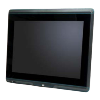
The UPC-F12C-ULT3 series is a quad-core Intel Core™ i5-6300U or Intel Celeron 3955U powered panel PC with a rich variety of functions and peripherals. The aluminum die-casting design and the IP66 enclosure make the UPC-F12C-ULT3 an ideal system for use in harsh environment. ® ®... -
Page 17: Model Variations
UPC-F12C-ULT3 Panel PC 1.2 Model Variations There are several models in the UPC-F12C-ULT3 series. The model numbers and model variations are listed below. Model Processor Touchscreen ® ® UPC-F12C-ULT3-C/R/4G Intel Celeron 3955U Resistive ® ® UPC-F12C-ULT3-C/PC/4G Intel Celeron 3955U Projected capacitive ®... -
Page 18: Front Panel
UPC-F12C-ULT3 Panel PC 1.4 Front Panel The front side of the UPC-F12C-ULT3 is a panel with a TFT LCD touchscreen surrounded by an aluminum die-casting frame (Figure 1-2). Figure 1-2: Front View 1.5 Rear Panel The rear panel of the UPC-F12C-ULT3 contains VESA mount screw holes. The rear panel also provides access for installing a 2.5"... -
Page 19: Bottom Panel
UPC-F12C-ULT3 Panel PC 1.6 Bottom Panel The bottom panel of the UPC-F12C-ULT3 has several I/O interfaces. The I/O cover must be removed to access the I/O interfaces. Figure 1-4: I/O Panel Page 5... -
Page 20: System Specifications
UPC-F12C-ULT3 Panel PC 1.7 System Specifications The technical specifications for the UPC-F12C-ULT3 systems are listed in Table 1-2. Specification UPC-F12C-ULT3 LCD Size 12.1" Max. Resolution 1024 (W) x 768 (H) Brightness (cd/m Contrast Ratio 700:1 LCD Color 16.2M Pixel Pitch (H x V) (mm) 0.24 x 0.24... -
Page 21: Table 1-2: System Specifications
UPC-F12C-ULT3 Panel PC Net/Gross Weight 5.02 kg / 7.40 kg Dimensions (W x H x D) 316.0 mm x 279.0 mm x 67.0 mm Operating Temperature -20ºC ~ 60ºC 0ºC~40ºC with FSP adapter (P/N: 63040-010096-100-RS on Page 14) Storage Temperature -20ºC ~ 70ºC... -
Page 22: Dimensions
UPC-F12C-ULT3 Panel PC 1.8 Dimensions The dimensions of the UPC-F12C-ULT3 are shown below. Figure 1-5: Dimensions (mm) Page 8... -
Page 23: Unpacking
UPC-F12C-ULT3 Panel PC Chapter Unpacking Page 9... -
Page 24: Unpacking
If any of the components listed in the checklist below are missing, do not proceed with the installation. Contact the IEI reseller or vendor the UPC-F12C-ULT3 was purchased from or contact an IEI sales representative directly by sending an email to sales@ieiworld.com. -
Page 25: Optional Items
UPC-F12C-ULT3 Panel PC The UPC-F12C-ULT3 panel PC is shipped with the following components: Quantity Item Image UPC-F12C-ULT3 panel PC Flat-head screw (M3*4) for HDD installation Touch pen (resistive type only) RJ-45 to DB-9 serial port cable Ferrite core for USB cable and LAN cable Protection grommet (six w/ blind hole;... - Page 26 UPC-F12C-ULT3 Panel PC Item and Part Number Image Stand for VESA 100 (P/N: STAND-A12-RS) Stand for VESA 75/VESA 100 (P/N: STAND-C12-R10) Mifare RFID kit (ATO only) (P/N: UPC-F-MF-RFID-KIT01-R10) 96 W power adapter with 4-pin DIN connector, (operating temperature: 0ºC~40ºC) (P/N: 63040-010096-100-RS) If any of these items are missing or damaged, contact the distributor or sales representative immediately.
-
Page 27: Installation
UPC-F12C-ULT3 Panel PC Chapter Installation Page 13... -
Page 28: Anti-Static Precautions
UPC-F12C-ULT3 and severe injury to the user. Electrostatic discharge (ESD) can cause serious damage to electronic components, including the UPC-F12C-ULT3. Dry climates are especially susceptible to ESD. It is therefore critical that whenever the UPC-F12C-ULT3 is accessed internally, or any other electrical component is handled, the following anti-static precautions are strictly adhered ... -
Page 29: Installation Precautions
UPC-F12C-ULT3 Panel PC 3.2 Installation Precautions CAUTION: The UPC-F12C-ULT3 series has more than one power supply connection point. To reduce the risk of electric shock, disconnect all power sources before installing or servicing the UPC-F12C-ULT3 series. When installing the panel PC, please follow the precautions listed below: ... -
Page 30: Figure 3-1: Hdd Slot Cover Retention Screws
UPC-F12C-ULT3 Panel PC Figure 3-1: HDD Slot Cover Retention Screws Step 2: Pull out the HDD bracket for installing HDD from the system. Figure 3-2: Remove HDD Bracket Step 3: Attach an HDD to the HDD brackets. To do this, align the four retention screw holes on the bottom side of the HDD with the retention screw holes in the HDD brackets. -
Page 31: Figure 3-3: Secure Hdd To The Bracket
Step 4: Insert the HDD bracket into the slot carefully until the bracket reach the end of the slot. Step 5: Connect the pre-installed SATA cable from the UPC-F12C-ULT3 to the rear of the HDD. Figure 3-4: HDD Installation Step 6: Re-install the HDD slot cover and secure it with two retention screws. -
Page 32: External I/O Connectors
UPC-F12C-ULT3 Panel PC 3.4 External I/O Connectors The UPC-F12C-ULT3 series is equipped with several I/O connectors for peripheral device connection. The pinouts of some of the external connectors are listed below. The pinouts of other external connectors are described in Section 5.3. -
Page 33: Clear Cmos
UPC-F12C-ULT3 Panel PC Use the RJ-45 to DB-9 serial port cable shipped with the UPC-F12C-ULT3 to connect to a serial device. The pinouts of the RJ-45 to DB-9 serial port cable are listed below. PIN NO. RS-232 RS-422 RS-485 TXD422-... -
Page 34: At/Atx Mode Selection
UPC-F12C-ULT3 Panel PC 3.4.4 AT/ATX Mode Selection AT or ATX power mode can be used on the UPC-F12C-ULT3. The selection is made through an AT/ATX switch located on the bottom panel (Figure 3-6). The I/O cover must be removed to be able to access the AT/ATX switch. -
Page 35: Protection Grommet Installation
Figure 3-9: Cable Installed with Ferrite Core 3.6 Protection Grommet Installation The UPC-F12C-ULT3 panel PC is shipped with several protection grommets which can be used to protect the I/O panel from water intrusion. To install the grommet, follow the steps below. -
Page 36: Figure 3-10: I/O Cover Retention Screws
UPC-F12C-ULT3 Panel PC Figure 3-10: I/O Cover Retention Screws Step 3: Insert a cable into a hole of the I/O cover corresponding to the system connector to be connected with. Connect the cable to the connector on the UPC-F12C-ULT3. Figure 3-11: Connect Cable to Connector Step 4: Put the cable into a grommet with suitable hole size. -
Page 37: Figure 3-12: Installing Grommet
Step 3 ~ Step 5 to connect necessary cables and install grommets. Step 7: Re-install the I/O cover onto the rear panel of the UPC-F12C-ULT3 by using six previously removed screws. Step 8: With the flat side facing upward, insert grommets with blind hole into those holes with no cables installed. -
Page 38: Mounting The System
3.7 Mounting the System The UPC-F12C-ULT3 is VESA (Video Electronics Standards Association) compliant and can be mounted on a mounting device with a 100 mm interface pad. The UPC-F12C-ULT3 VESA mount retention screw holes are shown in Figure 3-14. Refer to the installation guide that came with the mounting device to mount the UPC-F12C-ULT3. -
Page 39: Powering On The System
In ATX mode, long press the power button on the front panel for around five seconds until the LED lights up in green to power up the system. In AT mode, the UPC-F12C-ULT3 will turn on automatically once power is connected to the power connector; short press the power button to turn off/on the system. -
Page 40: Available Drivers
UPC-F12C-ULT3 Panel PC 3.9 Available Drivers All the drivers for the UPC-F12C-ULT3 are available on IEI Resource Download Center (https://download.ieiworld.com). Type UPC-F12C-ULT3 and press Enter to find all the relevant software, utilities, and documentation. Figure 3-17: IEI Resource Download Center 3.9.1 Driver Download... - Page 41 UPC-F12C-ULT3 Panel PC Step 3: Click the driver file name on the page and you will be prompted with the following window. You can download the entire ISO file ( ), or double click an individual item to find its driver file and click the file name to download (...
-
Page 42: Installing Windows 7 From Usb 3.2 Gen 1 Drives
The Windows 7 USB 3.0 Creator Utility automates the steps to update a Windows 7 installation image so that it contains USB 3.2 Gen 1 drivers. To install Windows 7 from a USB drive onto the UPC-F12C-ULT3, please follow the steps described below. -
Page 43: Bios Setup
UPC-F12C-ULT3 Panel PC Chapter BIOS Setup Page 29... -
Page 44: Introduction
UPC-F12C-ULT3 Panel PC 4.1 Introduction The BIOS is programmed onto the BIOS chip. The BIOS setup program allows changes to certain system settings. This chapter outlines the options that can be changed. NOTE: Some of the BIOS options may vary throughout the life cycle of the product and are subject to change without prior notice. -
Page 45: Getting Help
UPC-F12C-ULT3 Panel PC Function Decrease the numeric value or make changes F1 key General help, only for Status Page Setup Menu and Option Page Setup Menu F2 key Load previous values. F3 key Load optimized defaults F4 key Save changes and Exit BIOS Esc key Main Menu –... -
Page 46: Main
UPC-F12C-ULT3 Panel PC 4.2 Main The Main BIOS menu (BIOS Menu 1) appears when the BIOS Setup program is entered. Aptio Setup Utility – Copyright (C) 2017 American Megatrends, Inc. Main Advanced Chipset Security Boot Save & Exit BIOS Information... -
Page 47: Advanced
UPC-F12C-ULT3 Panel PC The System Overview field also has two user configurable fields: System Date [xx/xx/xx] Use the System Date option to set the system date. Manually enter the day, month and year. System Time [xx:xx:xx] Use the System Time option to set the system time. Manually enter the hours, minutes and seconds. -
Page 48: Acpi Settings
UPC-F12C-ULT3 Panel PC 4.3.1 ACPI Settings The ACPI Settings menu (BIOS Menu 3) configures the Advanced Configuration and Power Interface (ACPI) options. Aptio Setup Utility – Copyright (C) 2017 American Megatrends, Inc. Advanced ACPI Settings Select the highest ACPI sleep state the system... -
Page 49: Super Io Configuration
UPC-F12C-ULT3 Panel PC 4.3.2 Super IO Configuration Use the Super IO Configuration menu (BIOS Menu 4) to set or change the configurations for the serial ports. Aptio Setup Utility – Copyright (C) 2017 American Megatrends, Inc. Advanced F81866 Super IO Configuration... -
Page 50: Serial Port 1 Configuration
UPC-F12C-ULT3 Panel PC 4.3.2.1.1 Serial Port 1 Configuration Serial Port [Enabled] Use the Serial Port option to enable or disable the serial port. Disabled Disable the serial port Enable the serial port Enabled EFAULT Change Settings [Auto] Use the Change Settings option to change the serial port IO port address and interrupt address. -
Page 51: Serial Port 2 Configuration
UPC-F12C-ULT3 Panel PC 4.3.2.1.2 Serial Port 2 Configuration Serial Port [Enabled] Use the Serial Port option to enable or disable the serial port. Disabled Disable the serial port Enable the serial port Enabled EFAULT Change Settings [Auto] Use the Change Settings option to change the serial port IO port address and interrupt address. -
Page 52: Iwdd H/W Monitor
UPC-F12C-ULT3 Panel PC Transfer Mode [RS232] Use the Transfer Mode option to select the Serial Port 2 signaling mode. Serial Port 2 signaling mode is RS-422 RS422 Serial Port 2 signaling mode is RS-232 RS232 EFAULT ... -
Page 53: Rtc Wake Settings
UPC-F12C-ULT3 Panel PC System temperature K type 1 K type 2 Voltages +VCC_CORE +5VS +12VS +VDDQ +5VA +3.3V +3.3VSB 4.3.4 RTC Wake Settings The RTC Wake Settings menu (BIOS Menu 7) configures RTC wake event. Aptio Setup Utility – Copyright (C) 2017 American Megatrends, Inc. -
Page 54: Serial Port Console Redirection
UPC-F12C-ULT3 Panel PC Disabled The real time clock (RTC) cannot generate a wake EFAULT event Enabled If selected, the Wake up every day option appears allowing you to enable to disable the system to wake every day at the specified time. Besides, the... -
Page 55: Legacy Console Redirection Settings
UPC-F12C-ULT3 Panel PC Console Redirection [Disabled] Use Console Redirection option to enable or disable the console redirection function. Disabled the console redirection function Disabled EFAULT Enabled the console redirection function Enabled 4.3.5.1 Legacy Console Redirection Settings The Legacy Console Redirection Settings menu (BIOS Menu 9) allows the legacy console redirection options to be configured. -
Page 56: Console Redirection Settings
UPC-F12C-ULT3 Panel PC 4.3.5.2 Console Redirection Settings The Console Redirection Settings menu (BIOS Menu 10) allows the console redirection options to be configured. The option is active when Console Redirection option is enabled. Aptio Setup Utility – Copyright (C) 2017 American Megatrends, Inc. - Page 57 UPC-F12C-ULT3 Panel PC Bits per second [115200] Use the Bits per second option to specify the serial port transmission speed. The speed must match the other side. Long or noisy lines may require lower speeds. 9600 Sets the serial port transmission speed at 9600.
-
Page 58: Cpu Configuration
UPC-F12C-ULT3 Panel PC Stop Bits [1] Use the Stop Bits option to specify the number of stop bits used to indicate the end of a serial data packet. Communication with slow devices may require more than 1 stop bit. - Page 59 UPC-F12C-ULT3 Panel PC Hyper Threading Function [Enabled] Use the Hyper Threading function to enable or disable the CPU hyper threading function. Disables the use of hyper threading technology Disabled Enables the use of hyper threading technology Enabled EFAULT ...
-
Page 60: Sata Configuration
UPC-F12C-ULT3 Panel PC CPU C State [Disabled] Use the CPU C State option to enable or disable CPU C state. Disables CPU C state. Disabled EFAULT Enables CPU C state. Enabled 4.3.7 SATA Configuration Use the SATA Configuration menu (BIOS Menu 12) to change and/or set the configuration of the SATA devices installed in the system. - Page 61 UPC-F12C-ULT3 Panel PC SATA Mode Selection [AHCI] Use the SATA Mode Selection option to configure SATA devices as AHCI devices. Configures SATA devices as AHCI device. AHCI EFAULT Configures SATA devices as RAID device. RAID NOTE: Before accessing the RAID configuration utility, ensure to set the Option ROM Messages BIOS option in the Boot menu to Force BIOS.
-
Page 62: Usb Configuration
UPC-F12C-ULT3 Panel PC 4.3.8 USB Configuration Use the USB Configuration menu (BIOS Menu 13) to read USB configuration information and configure the USB settings. Aptio Setup Utility – Copyright (C) 2017 American Megatrends, Inc. Advanced USB Configuration Enables Legacy USB support. -
Page 63: Iei Feature
UPC-F12C-ULT3 Panel PC Enabled Legacy USB support enabled EFAULT Legacy USB support disabled Disabled Auto Legacy USB support disabled if no USB devices are connected 4.3.9 IEI Feature Use the IEI Feature menu (BIOS Menu 14) to configure One Key Recovery function. -
Page 64: Chipset
UPC-F12C-ULT3 Panel PC 4.4 Chipset Use the Chipset menu (BIOS Menu 15) to configure the system chipset. Aptio Setup Utility – Copyright (C) 2017 American Megatrends, Inc. Main Advanced Chipset Security Boot Save & Exit > System Agent (SA) Configuration System Agent (SA) >... -
Page 65: Graphics Configuration
UPC-F12C-ULT3 Panel PC VT-d [Disabled] Use the VT-d option to enable or disable VT-d support. Disable VT-d support. Disabled EFAULT Enable VT-d support. Enabled 4.4.1.1 Graphics Configuration Use the Graphics Configuration menu (BIOS Menu 17) to configure the graphics settings. -
Page 66: Lcd Control
UPC-F12C-ULT3 Panel PC 256M EFAULT 512M DVMT Total Gfx Mem [MAX] Use the DVMT Total Gfx Mem option to select DVMT 5.0 total graphic memory size used by the internal graphics device. The following options are available: ... -
Page 67: Memory Configuration
UPC-F12C-ULT3 Panel PC Primary IGFX Boot Display [VBIOS Default] Use the Primary IGFX Boot Display option to select the display device used by the system when it boots. VBIOS Default EFAULT LVDS HDMI On board LVDS [Enabled] Use the On board LVDS option to enable or disable the on-board LVDS connector. -
Page 68: Pch-Io Configuration
UPC-F12C-ULT3 Panel PC 4.4.2 PCH-IO Configuration Use the PCH-IO Configuration menu (BIOS Menu 20) to configure the PCH-IO chipset. Aptio Setup Utility – Copyright (C) 2017 American Megatrends, Inc. Chipset Auto Power Button Status [Disable (ATX)] Select AC power state when... -
Page 69: Pci Express Configuration
UPC-F12C-ULT3 Panel PC USB Power SW [+5V DUAL] Use the USB Power SW BIOS option to configure the USB power source for the corresponding USB connector. +5V DUAL Set the USB power source to +5V dual EFAULT ... -
Page 70: Security
UPC-F12C-ULT3 Panel PC Detect Non-Compliance Device [Disabled] Use the Detect Non-Compliance Device option to enable or disable detecting if a non-compliance PCI Express device is connected to the PCI Express slot. Disabled Disables to detect if a non-compliance PCI... -
Page 71: Boot
UPC-F12C-ULT3 Panel PC 4.6 Boot Use the Boot menu (BIOS Menu 23) to configure system boot options. Aptio Setup Utility – Copyright (C) 2017 American Megatrends, Inc. Main Advanced Chipset Security Boot Save & Exit Boot Configuration Select the keyboard... - Page 72 UPC-F12C-ULT3 Panel PC Quiet Boot [Enabled] Use the Quiet Boot BIOS option to select the screen display when the system boots. Normal POST messages displayed Disabled OEM Logo displayed instead of POST messages Enabled EFAULT Launch PXE OpROM [Disabled] Use the Launch PXE OpROM option to enable or disable boot option for legacy network devices.
-
Page 73: Save & Exit
UPC-F12C-ULT3 Panel PC 4.7 Save & Exit Use the Save & Exit menu (BIOS Menu 24) to load default BIOS values, optimal failsafe values and to save configuration changes. Aptio Setup Utility – Copyright (C) 2017 American Megatrends, Inc. Main... - Page 74 UPC-F12C-ULT3 Panel PC Save as User Defaults Use the Save as User Defaults option to save the changes done so far as user defaults. Restore User Defaults Use the Restore User Defaults option to restore the user defaults to all the setup options.
-
Page 75: Interface Connectors
UPC-F12C-ULT3 Panel PC Chapter Interface Connectors Page 61... -
Page 76: Peripheral Interface Connectors
UPC-F12C-ULT3 Panel PC 5.1 Peripheral Interface Connectors The UPC-F12C-ULT3 medical box PC motherboard comes with a number of peripheral interface connectors and configuration jumpers. The connector locations are shown in Figure 5-1. The Pin 1 locations of the on-board connectors are also indicated in the diagram below. -
Page 77: Internal Peripheral Connectors
Internal peripheral connectors are found on the motherboard and are only accessible when the motherboard is outside of the chassis. The table below shows a list of the peripheral interface connectors on the UPC-F12C-ULT3’s motherboard. Pinouts of these connectors can be found in the following sections. - Page 78 UPC-F12C-ULT3 Panel PC Digital I/O connector 10-pin header DIO1 Fan connector (CPU) 4-pin wafer CPU_FAN1 Heater power output connectors 2-pin wafer H_CN1, H_CN2 Keyboard/Mouse connector 6-pin wafer KB_MS1 K-type thermocouple connectors 2-pin wafer K_TYPE1, K_TYPE2 LAN 1 LED connector 2-pin header...
-
Page 79: Audio Connector (Audio1)
UPC-F12C-ULT3 Panel PC U72 FW programming connector 9-pin wafer Table 5-1: Peripheral Interface Connectors 5.2.1 Audio Connector (AUDIO1) PIN NO. DESCRIPTION PIN NO. DESCRIPTION SPK_OUT-R LINE_IN-R SPK_OUT-L LINE_IN-L MIC-R MIC-L Table 5-2: Audio Connector (AUDIO1) Pinouts 5.2.2 Battery Connector (BAT1) PIN NO. -
Page 80: Debug Port, Ec (Lpt_Db1)
UPC-F12C-ULT3 Panel PC 5.2.4 Debug Port, EC (LPT_DB1) PIN NO. DESCRIPTION PIN NO. DESCRIPTION EC_EPP_STB# EC_EPP_AFD# EC_EPP_PD0 EC_EPP_PD1 EC_EPP_INIT# EC_EPP_PD2 EC_EPP_SLIN# EC_EPP_PD3 EC_EPP_PD4 EC_EPP_PD5 EC_EPP_BUSY EC_EPP_PD6 EC_EPP_KSI5 EC_EPP_PD7 EC_EPP_KSI4 Table 5-5: Debug Port, EC (LPT_DB1) Pinouts 5.2.5 Digital I/O Connector (DIO1) PIN NO. -
Page 81: Heater Power Output Connectors (H_Cn1, H_Cn2)
UPC-F12C-ULT3 Panel PC 5.2.7 Heater Power Output Connectors (H_CN1, H_CN2) PIN NO. DESCRIPTION PIN NO. DESCRIPTION 12 V ~ 36 V Table 5-8: Heater Power Output Connectors (H_CN1, H_CN2) Pinouts 5.2.8 Keyboard/Mouse Connector (KB_MS1) PIN NO. DESCRIPTION VCC5_KBMS MSDATA MSCLK... -
Page 82: Lan 2 Led Connector (Jp3)
UPC-F12C-ULT3 Panel PC 5.2.11 LAN 2 LED Connector (JP3) PIN NO. DESCRIPTION PIN NO. DESCRIPTION +V3.3A LAN2_LINK_ACT- Table 5-12: LAN 2 LED Connector (JP3) Pinouts 5.2.12 LCD Inverter Connector (INVERTER1) PIN NO. DESCRIPTION +12V +12V Backlight ON/OFF Backlight Brightness Control Table 5-13: LCD Inverter Connector (INVERTER1) Pinouts 5.2.13 LED Indicator Connector (CN1) -
Page 83: Lvds Connector (Lvds1)
UPC-F12C-ULT3 Panel PC 5.2.14 LVDS Connector (LVDS1) PIN NO. DESCRIPTION PIN NO. DESCRIPTION GROUND GROUND LVDS_A_TX0-N LVDS_A_TX1-N LVDS_A_TX0-P LVDS_A_TX1-P GROUND GROUND LVDS_A_TX2-N LVDS_A_TXCLK-N LVDS_A_TX2-P LVDS_A_TXCLK-P GROUND GROUND LVDS_A_TX3-N LVDS_B_TX0-N LVDS_A_TX3-P LVDS_B_TX0-P GROUND GROUND LVDS_B_TX1-N LVDS_B_TX2-N LVDS_B_TX1-P LVDS_B_TX2-P GROUND GROUND LVDS_B_TXCLK-N... - Page 84 UPC-F12C-ULT3 Panel PC PIN NO. DESCRIPTION PIN NO. DESCRIPTION Module Key Module Key Module Key Module Key Module Key Module Key Module Key Module Key GNSS_DISABLE# USB3_RX- USB3_RX+ USB3_TX- USB3_TX+ PCIE_RX-/SATA_RX+ PCIE_RX+/SATA_RX- PCIE_TX-/SATA_TX- PCIE_TX+/SATA_TX+ CLK_PCIE- PCIE_WAKE# CLK_PCIE+ BUF_PLT_RST# +V3.3S +V3.3S +V3.3S...
-
Page 85: Pcie Mini Slot (Mini_Pcie1)
UPC-F12C-ULT3 Panel PC PIN NO. DESCRIPTION PIN NO. DESCRIPTION Table 5-16: M.2 Slot (M_2_BKEY1) Pinouts 5.2.16 PCIe Mini Slot (MINI_PCIE1) PIN NO. DESCRIPTION PIN NO. DESCRIPTION PCIE_WAKE# +3.3V +1.5V CLK- CLK+ PCIRST# +3.3V PCIRST# PERN +3VDual PERP +1.5V SMBCLK PETN... -
Page 86: Connectors (Com3, Com4)
UPC-F12C-ULT3 Panel PC PIN NO. DESCRIPTION PIN NO. DESCRIPTION MSATA_SEL# +3.3V Table 5-17: PCIe Mini Slot (MINI_PCIE1) Pinouts 5.2.17 RS-232 Connectors (COM3, COM4) PIN NO. DESCRIPTION PIN NO. DESCRIPTION -NDCD -NDSR NSIN -NRTS NSOUT -NCTS -NDTR -XRI Table 5-18: RS-232 Connector (COM3, COM4) Pinouts 5.2.18 RS-232/422/485 Connector (COM5) -
Page 87: Sata 6Gb/S Connector (Sata1)
UPC-F12C-ULT3 Panel PC 5.2.19 SATA 6Gb/s Connector (SATA1) PIN NO. DESCRIPTION PIN NO. DESCRIPTION SATA_TX+ SATA_TX- SATA_RX- SATA RX+ Table 5-20: SATA 6Gb/s Connector (SATA1) Pinouts 5.2.20 SMBus Connector (SMBUS1) PIN NO. DESCRIPTION SMBUS DATA SMBUS CLOCK +5 V Table 5-21: SMBus Connector (SMBUS1) Pinouts 5.2.21 Power Button Connector (PWR_BTN1) -
Page 88: Reset Button Connector (Rst_Btn1)
UPC-F12C-ULT3 Panel PC 5.2.22 Reset Button Connector (RST_BTN1) PIN NO. DESCRIPTION RESET+ RESET- Table 5-23: Reset Button Connector (RST_BTN1) Pinouts 5.2.23 SPI Flash Connector, BIOS (JSPI1) PIN NO. DESCRIPTION +V3.3M_SPI_CON SPI_CS SPI_SO_SW SPI_CLK_SW SPI_SI_SW Table 5-24: SPI Flash Connector (JSPI1) Pinouts 5.2.24 SPI Flash Connector, EC (JSPI2) -
Page 89: Touchscreen Connector (Touch1)
UPC-F12C-ULT3 Panel PC 5.2.25 Touchscreen Connector (TOUCH1) PIN NO. 8-wire 4-wire 5-wire Right Sense Left Sense Bottom Sense Top Sense Sense (S) Right Excite Right LR (X) Left Excite Left LL (L) Bottom Excite Bottom UR (H) Top Excite UL (Y) Table 5-26: Touchscreen Connector (TOUCH1) Pinouts 5.2.26 USB 2.0 Connector for Touch (USB1) -
Page 90: U72 Fw Programming Connector (Jp1)
UPC-F12C-ULT3 Panel PC 5.2.28 U72 FW Programming Connector (JP1) PIN NO. DESCRIPTION MCLR VCC5_MCU ICSPCLK ICSPDAT MCU_IR AUTO_CLK AUTO_DATA Table 5-29: U72 FW Programming Connector (JP1) Pinouts 5.3 External Interface Panel Connectors The table below lists the rear panel connectors on the motherboard. Pinouts of these connectors can be found in the following sections. -
Page 91: Hdmi Connector (Hdmi1)
UPC-F12C-ULT3 Panel PC 5.3.1 HDMI Connector (HDMI1) PIN NO. DESCRIPTION PIN NO. DESCRIPTION HDMI_DATA2+ HDMI_CLK# HDMI_DATA2#- HDMI_DATA1+ HDMI_SCL HDMI_DATA1#- HDMI_SDA HDMI_DATA0+ +5VCC HDMI_DATA0#- HDMI_HPD HDMI_CLK+ Table 5-31: HDMI Connector (HDMI1) Pinouts 5.3.2 Ethernet Connectors (LAN1, LAN2) PIN NO. DESCRIPTION PIN NO. -
Page 92: Usb 3.2 Gen 1 Connectors (Usb3_Con1)
UPC-F12C-ULT3 Panel PC 5.3.4 USB 3.2 Gen 1 Connectors (USB3_CON1) PIN NO. DESCRIPTION PIN NO. DESCRIPTION USB2P0_DM0 USB2P0_DM1 USB2P0_DP0 USB2P0_DP1 USB3P0_RXDN0 USB3P0_RXDN1 USB3P0_RXDP0 USB3P0_RXDP1 USB3P0_TXDN0 USB3P0_TXDN1 USB3P0_TXDP0 USB3P0_TXDP1 Table 5-34: USB 3.2 Gen 1 Connectors (USB3_CON1) Pinouts 5.3.5 VGA Connector (VGA1) PIN NO. -
Page 93: Preconfigured Jumper Settings
UPC-F12C-ULT3 Panel PC 5.4 Preconfigured Jumper Settings CAUTION: The following jumpers are preconfigured for the UPC-F12C-ULT3. Users should not change these jumpers (Table 5-36). Jumper Name Type Label LVDS voltage selection 6-pin header JLCD_PWR1 LVDS panel resolution selection Switch Table 5-36: Preconfigured Jumpers 5.4.1 LVDS Panel Voltage Selection Jumper (JLCD_PWR1) -
Page 94: Table 5-38: Lvds Resolution Selection Jumper (Sw1) Settings
UPC-F12C-ULT3 Panel PC SW1 (4-3-2-1) Description 0110 1280x1024 24bit D 0111 1366x768 18bit S 1000 1366x768 24bit S 1001 1440x960 24bit D 1010 1400x1050 24bit D 1011 1600x900 24bit D 1100 1680x1050 24bit D 1101 1600x1200 24bit D 1110 1920x1080 24bit D... -
Page 95: A Regulatory Compliance
UPC-F12C-ULT3 Panel PC Appendix Regulatory Compliance Page 81... - Page 96 UPC-F12C-ULT3 Panel PC DECLARATION OF CONFORMITY This equipment is in conformity with the following EU directives: EMC Directive 2014/30/EU Low-Voltage Directive 2014/35/EU RoHS II Directive 2015/863/EU If the user modifies and/or install other devices in the equipment, the CE conformity declaration may no longer apply.
- Page 97 UPC-F12C-ULT3 Panel PC Español [Spanish] IEI Integration Corp declara que el equipo cumple con los requisitos esenciales y cualesquiera otras disposiciones aplicables o exigibles de la Directiva 1999/5/CE. Ελληνική [Greek] IEI Integration Corp ΔΗΛΩΝΕΙ ΟΤΙ ΕΞΟΠΛΙΣΜΟΣ ΣΥΜΜΟΡΦΩΝΕΤΑΙ ΠΡΟΣ ΤΙΣ ΟΥΣΙΩΔΕΙΣ ΑΠΑΙΤΗΣΕΙΣ ΚΑΙ ΤΙΣ ΛΟΙΠΕΣ ΣΧΕΤΙΚΕΣ ΔΙΑΤΑΞΕΙΣ ΤΗΣ ΟΔΗΓΙΑΣ...
- Page 98 UPC-F12C-ULT3 Panel PC Româna [Romanian] IEI Integration Corp declară că acest echipament este in conformitate cu cerinţele esenţiale şi cu celelalte prevederi relevante ale Directivei 1999/5/CE. Slovensko [Slovenian] IEI Integration Corp izjavlja, da je ta opreme v skladu z bistvenimi zahtevami in ostalimi relevantnimi določili direktive 1999/5/ES.
- Page 99 UPC-F12C-ULT3 Panel PC FCC WARNING This equipment complies with Part 15 of the FCC Rules. Operation is subject to the following two conditions: This device may not cause harmful interference, and This device must accept any interference received, including interference that may cause undesired operation.
-
Page 100: B Safety Precautions
UPC-F12C-ULT3 Panel PC Appendix Safety Precautions Page 86... -
Page 101: Safety Precautions
Electric shocks can occur if the UPC-F12C-ULT3 chassis is opened when it is running. To avoid risk of electric shock, this device must only be connected to a supply mains with protective earth. -
Page 102: Anti-Static Precautions
Electrostatic discharge (ESD) can cause serious damage to electronic components, including the UPC-F12C-ULT3. Dry climates are especially susceptible to ESD. It is therefore critical that whenever the UPC-F12C-ULT3 is opened and any of the electrical components are handled, the following anti-static precautions are strictly adhered to. -
Page 103: Product Disposal
UPC-F12C-ULT3 Panel PC B.1.3 Product Disposal CAUTION: Risk of explosion if battery is replaced by an incorrect type. Only certified engineers should replace the on-board battery. Dispose of used batteries according to instructions and local regulations. Outside the European Union–If you wish to dispose of used electrical and electronic products outside the European Union, please contact your local authority so as to comply with the correct disposal method. -
Page 104: Maintenance And Cleaning Precautions
Some components in the UPC-F12C-ULT3 may only be cleaned using a product specifically designed for the purpose. In such case, the product will be explicitly mentioned in the cleaning tips. Below is a list of items to use when cleaning the UPC-F12C-ULT3. ... - Page 105 UPC-F12C-ULT3 Panel PC Water or rubbing alcohol–A cloth moistened with water or rubbing alcohol can be used to clean the device. Using solvents–The use of solvents is not recommended when cleaning the device as they may damage the plastic parts.
-
Page 106: Cbios Menu Options
UPC-F12C-ULT3 Panel PC Appendix BIOS Menu Options Page 92... - Page 107 UPC-F12C-ULT3 Panel PC System Date [xx/xx/xx] ......................33 System Time [xx:xx:xx] ....................... 33 ACPI Sleep State [S3 (Suspend to RAM)] ................34 Serial Port [Enabled] ......................36 Change Settings [Auto] ....................... 36 Serial Port [Enabled] ......................37 Change Settings [Auto] ....................... 37 Transfer Mode [RS232] ......................
- Page 108 UPC-F12C-ULT3 Panel PC Power Saving Function(ERP) [Disabled] ................54 USB Power SW [+5V DUAL] ....................55 PCIe Speed [Auto] ........................ 55 Detect Non-Compliance Device [Disabled] ............... 56 Administrator Password ..................... 56 User Password ........................56 Bootup NumLock State [On] ....................57 Quiet Boot [Enabled] ......................
-
Page 109: D Watchdog Timer
UPC-F12C-ULT3 Panel PC Appendix Watchdog Timer Page 95... - Page 110 UPC-F12C-ULT3 Panel PC NOTE: The following discussion applies to DOS. Contact IEI support or visit the IEI website for drivers for other operating systems. The Watchdog Timer is a hardware-based timer that attempts to restart the system when it stops working. The system may stop working because of external EMI or software bugs.
- Page 111 UPC-F12C-ULT3 Panel PC NOTE: The Watchdog Timer is activated through software. The software application that activates the Watchdog Timer must also deactivate it when closed. If the Watchdog Timer is not deactivated, the system will automatically restart after the Timer has finished its countdown.
-
Page 112: E Hazardous Materials Disclosure
UPC-F12C-ULT3 Panel PC Appendix Hazardous Materials Disclosure Page 98... -
Page 113: Rohs Ii Directive (2015/863/Eu)
UPC-F12C-ULT3 Panel PC E.1 RoHS II Directive (2015/863/EU) The details provided in this appendix are to ensure that the product is compliant with the RoHS II Directive (2015/863/EU). The table below acknowledges the presences of small quantities of certain substances in the product, and is applicable to RoHS II Directive (2015/863/EU). -
Page 114: China Rohs
UPC-F12C-ULT3 Panel PC E.2 China RoHS 此附件旨在确保本产品符合中国 RoHS 标准。以下表格标示此产品中某有毒物质的含量符 合中国 RoHS 标准规定的限量要求。 本产品上会附有”环境友好使用期限”的标签,此期限是估算这些物质”不会有泄漏或突变”的 年限。本产品可能包含有较短的环境友好使用期限的可替换元件,像是电池或灯管,这些 元件将会单独标示出来。 部件名称 有毒有害物质或元素 壳体 显示 印刷电路板 金属螺帽 电缆组装 风扇组装 电力供应组装 电池 O: 表示该有毒有害物质在该部件所有物质材料中的含量均在 SJ/T11364-2014 與 GB/T26572-2011 标准规定的限量要求以下。 X: 表示该有毒有害物质至少在该部件的某一均质材料中的含量超出 SJ/T11364-2014 與 GB/T26572-2011 标准规定的限量要求。 Page 100...
Need help?
Do you have a question about the UPC-F12C-ULT3 and is the answer not in the manual?
Questions and answers