Table of Contents
Advertisement
Quick Links
Advertisement
Chapters
Table of Contents

Related Manuals for IEI Technology AFL3-W22C-ULT3


Summary of Contents for IEI Technology AFL3-W22C-ULT3
- Page 1 AFL3-W15C/W19C/W22C-ULT3 Panel PC MODEL: AFL3-W15C/W19C/W22C-ULT3 Flat Bezel Panel PC with Intel® Core™ i5-6300U / Celeron® 3955U CPU, Touchscreen, Four USB 3.1 Gen 1, Dual GbE LAN, RS-232/422/485, HD Audio, Wi-Fi 802.11a/b/g/n/ac and RoHS User Manual User Manual Page I Rev. 1.31 - May 23, 2019...
- Page 2 1.30 Updated for R13 version – upgraded to anti-glare touch screen Added E-Window module support list September 6, 2017 1.02 Added the AFL3-W22C-ULT3 model information March 1, 2017 1.01 Modified the brightness specification of the AFL3-W15C-ULT3 November 1, 2016 1.00...
- Page 3 AFL3-W15C/W19C/W22C-ULT3 Panel PC Safety Instructions Warning! Read the user manual before connecting the system to the power source. Vorsicht! Bitte lesen Sie die Bedienungsanleitung, bevor Sie das System an eine Stromquelle anschließen. Attention! Avant de brancher le système à la source d'alimentation, consultez le mode d'emploi.
- Page 4 AFL3-W15C/W19C/W22C-ULT3 Panel PC another type of adapter may risk fire or explosion. Please refer to the user manual for the power adapter specifications. Vorsicht! Nur zugelassene Netzteile und Netzkabel dürfen verwendet werden. Die Benutzung von anderen Netzteilen kann einen Brand oder eine Explosion zur Folge haben.
- Page 5 AFL3-W15C/W19C/W22C-ULT3 Panel PC Copyright COPYRIGHT NOTICE The information in this document is subject to change without prior notice in order to improve reliability, design and function and does not represent a commitment on the part of the manufacturer. In no event will the manufacturer be liable for direct, indirect, special, incidental, or consequential damages arising out of the use or inability to use the product or documentation, even if advised of the possibility of such damages.
- Page 6 AFL3-W15C/W19C/W22C-ULT3 Panel PC Manual Conventions WARNING Warnings appear where overlooked details may cause damage to the equipment or result in personal injury. Warnings should be taken seriously. CAUTION Cautionary messages should be heeded to help reduce the chance of losing data or damaging the product. NOTE These messages inform the reader of essential but non-critical information.
-
Page 7: Table Of Contents
.................... 8 YSTEM PECIFICATIONS 1.9 D ......................11 IMENSIONS 1.9.1 AFL3-W15C-ULT3 Dimensions ................ 11 1.9.2 AFL3-W19C-ULT3 Dimensions ............... 12 1.9.3 AFL3-W22C-ULT3 Dimensions ............... 13 2 UNPACKING ....................... 14 2.1 U ......................15 NPACKING 2.2 P ......................15 ACKING 2.3 O ...................... - Page 8 AFL3-W15C/W19C/W22C-ULT3 Panel PC 3.10 C CMOS ......................36 LEAR 3.11 AT/ATX M ..................37 ELECTION 3.11.1 AT Power Mode ....................37 3.11.2 ATX Power Mode ................... 37 3.12 M ..................38 OUNTING THE YSTEM 3.12.1 Wall Mounting ....................38 3.12.2 Panel Mounting ....................41 3.12.3 Cabinet and Rack Installation ...............
- Page 9 AFL3-W15C/W19C/W22C-ULT3 Panel PC 4.3.5.1 Legacy Console Redirection Settings ............70 4.3.5.2 Console Redirection Settings ..............71 4.3.6 CPU Configuration ..................73 4.3.7 SATA Configuration ..................75 4.3.8 USB Configuration ................... 77 4.3.9 IEI Feature ....................... 78 4.4 C ........................79 HIPSET 4.4.1 System Agent (SA) Configuration ..............
- Page 10 AFL3-W15C/W19C/W22C-ULT3 Panel PC 6.2.9 M.2 M-key Slot (M2_M_KEY) ............... 102 6.2.10 MCU Connector (HOTKEY_CN1) .............. 103 6.2.11 Microphone Connector (DMIC1) ..............104 6.2.12 PCIe Mini Connector, Full-Size/Half-size (M_PCIE1) ....... 104 6.2.13 Power Button Connector (PW_BTN1) ............105 6.2.14 Power LED Connector (PW_LED1) ............105 6.2.15 RS-232 Serial Port Connector (COM3) ............
- Page 11 AFL3-W15C/W19C/W22C-ULT3 Panel PC B.1.2 Anti-static Precautions .................. 123 B.1.3 Product Disposal ................... 124 B.2 M ............125 AINTENANCE AND LEANING RECAUTIONS B.2.1 Maintenance and Cleaning ................125 B.2.2 Cleaning Tools ....................125 C BIOS MENU OPTIONS ................... 127 D WATCHDOG TIMER ....................130 E HAZARDOUS MATERIALS DISCLOSURE ............
- Page 12 Figure 3-1: AFL3-W15C-ULT3 Back Cover Retention Screws ..........22 Figure 3-2: AFL3-W19C-ULT3 Back Cover Retention Screws ..........22 Figure 3-3: AFL3-W22C-ULT3 Back Cover Retention Screws ..........23 Figure 3-4: AFL3-W15C-ULT3 Aluminum Cover Retention Screws ........24 Figure 3-5: AFL3-W19C-ULT3 Aluminum Cover Retention Screws ........24 Figure 3-6: AFL3-W22C-ULT3 Aluminum Cover Retention Screws ........
- Page 13 Figure 3-26: Secure the Panel PC ....................41 Figure 3-27: AFL3-W15C-ULT3 Cutout Dimensions ..............41 Figure 3-28: AFL3-W19C-ULT3 Cutout Dimensions ..............42 Figure 3-29: AFL3-W22C-ULT3 Cutout Dimensions ..............42 Figure 3-30: Panel Mounting Kit Installation ................43 Figure 3-31: Securing Panel Mounting Brackets ............... 44 Figure 3-32: Rack Mounting Kit Installation ................
- Page 14 AFL3-W15C/W19C/W22C-ULT3 Panel PC List of Tables Table 1-1: Model Variations ......................3 Table 1-2: Supported E-Window Modules ..................7 Table 1-3: System Specifications ....................10 Table 3-1: PCIe Mini Slot Mode Selection (MSATA_CN1) ............31 Table 3-2: COM1 Pin 9 Setting Jumper Settings (JP5) ............. 34 Table 3-3: COM2 Pin 9 Setting Jumper Settings (JP4) .............
- Page 15 AFL3-W15C/W19C/W22C-ULT3 Panel PC Table 6-23: USB Connector (BT_USB1) Pinouts ..............108 Table 6-24: USB Connector (CAM_USB1) Pinouts ..............108 Table 6-25: USB Connector (RFID_USB1) Pinouts ..............108 Table 6-26: USB Connector (TOUCH_USB1) Pinouts .............109 Table 6-27: USB 2.0 Connector (USB20_CN1) Pinouts ............109 Table 6-28: USB Power Connector (USB_PWR1) Pinouts............109 Table 6-29: Rear Panel Connectors ..................110 Table 6-30: Ethernet Connectors (LAN2 &...
- Page 16 AFL3-W15C/W19C/W22C-ULT3 Panel PC List of BIOS Menus BIOS Menu 1: Main ........................59 BIOS Menu 2: Advanced ......................60 BIOS Menu 3: ACPI Settings ....................... 61 BIOS Menu 4: F81866 Super IO Configuration ................62 BIOS Menu 5: Serial Port n Configuration ................. 62 BIOS Menu 6: F81866 H/W Monitor .....................
-
Page 17: Introduction
AFL3-W15C/W19C/W22C-ULT3 Panel PC Chapter Introduction Page 1... -
Page 18: Overview
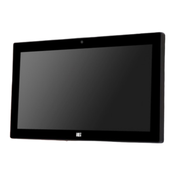
AFL3-W15C/W19C/W22C-ULT3 Panel PC 1.1 Overview Figure 1-1: AFL3-W15C/W19C/W22C-ULT3 Flat Bezel Panel PC ® The AFL3-W15C/W19C/W22C-ULT3 series is a quad-core Intel Core™ i5-6300U or ® ® Intel Celeron 3955U powered flat bezel touchscreen panel PC with a rich variety of functions and peripherals. The flat-bezel design is ideal for easy and simplified integration into various applications. -
Page 19: Model Variations
AFL3-W19C-ULT3-C/PC/4G ® ® 18.5” Intel Celeron 3955U Projected capacitive type AFL3-W19C-ULT3-i5/PC/4G ® 18.5” Intel Core™ i5-6300U Projected capacitive type AFL3-W22C-ULT3-C/PC/4G ® ® 21.5” Intel Celeron 3955U Projected capacitive type AFL3-W22C-ULT3-i5/PC/4G ® 21.5” Intel Core™ i5-6300U Projected capacitive type Table 1-1: Model Variations 1.3 Features... -
Page 20: Front Panel
AFL3-W15C/W19C/W22C-ULT3 Panel PC Optional magnetic stripe card reader 9 V–30 V wide range DC power input IP 64 compliant front panel 1.4 Front Panel The front side of the AFL3-W15C/W19C/W22C-ULT3 is a flat-bezel panel with a TFT LCD screen surrounded by a PC/ABS plastic frame (Figure 1-2). -
Page 21: Bottom Panel
AFL3-W15C/W19C/W22C-ULT3 Panel PC 1.5 Bottom Panel The bottom panel of the AFL3-W15C/W19C/W22C-ULT3 has the following connectors and switches (Figure 1-5). Figure 1-3: AFL3-W15C-ULT3 Bottom Panel Figure 1-4: AFL3-W19C-ULT3 Bottom Panel Figure 1-5: AFL3-W22C-ULT3 Bottom Panel Page 5... -
Page 22: Rear Panel
AFL3-W15C/W19C/W22C-ULT3 Panel PC 1.6 Rear Panel The rear panel has two speakers and retention screw holes that support VESA mounting. The rear panel also has several retention screw holes for installing the optional barcode scanner and magnetic stripe card reader. Figure 1-6: AFL3-W19C-ULT3 Rear View Page 6... -
Page 23: Side Panel
E-MPCIE-LAN02 PCIe Mini card supports one GbE port with Realtek RTL8111E AFL3-W19C-ULT3 controller, PMS 194C I/O bracket and 340 mm cable AFL3-W22C-ULT3 E-MPCIE-CClink PCIe Mini card supports CC-Link Slave interface V2.0 and AFL3-W15C-ULT3 V1.1, with black C I/O bracket and 250mm cable E-MPCIE-CClink02 PCIe Mini card supports CC-Link Slave interface V2.0 and... -
Page 24: System Specifications
AFL3-W15C/W19C/W22C-ULT3 Panel PC 1.8 System Specifications The technical specifications for the AFL3-W15C/W19C/W22C-ULT3 systems are listed in Table 1-3. Specification AFL3-W15C-ULT3 AFL3-W19C-ULT3 AFL3-W22C-ULT3 LCD Size 15.6" (16:9) 18.5” (16:9) 21.5” (16:9) Max. Resolution 1366 (W) x 768 (H) 1366 (W) x 768 (H) - Page 25 AFL3-W15C/W19C/W22C-ULT3 Panel PC Storage One full-size/half-size PCIe Mini slot supports mSATA module One M.2 M-key slot for M.2 2280 module installation One 2.5” SATA 3Gb/s HDD bay Audio Realtek ALC892 HD Audio codec Internal Speaker Two 3 W Camera 2-megapixel with low light function and digital microphone Wireless &...
-
Page 26: Table 1-3: System Specifications
AFL3-W15C/W19C/W22C-ULT3 Panel PC Output: 12 V DC, 8 A Power Requirement 9 V ~ 30 V DC Power Consumption 56 W, 12 V @ 4.6 A 86 W, 12 V @ 7.1 A 75 W, 12 V @ 6.25 A IP Level IP 64 compliant front panel Safety/EMC... -
Page 27: Dimensions
AFL3-W15C/W19C/W22C-ULT3 Panel PC 1.9 Dimensions The following sections list the dimensions of each model. 1.9.1 AFL3-W15C-ULT3 Dimensions The AFL3-W15C-ULT3 dimensions are shown below. Figure 1-8: AFL3-W15C-ULT3 Dimensions (mm) Page 11... -
Page 28: Afl3-W19C-Ult3 Dimensions
AFL3-W15C/W19C/W22C-ULT3 Panel PC 1.9.2 AFL3-W19C-ULT3 Dimensions The AFL3-W19C-ULT3 dimensions are shown below. Figure 1-9: AFL3-W19C-ULT3 Dimensions (mm) Page 12... -
Page 29: Afl3-W22C-Ult3 Dimensions
AFL3-W15C/W19C/W22C-ULT3 Panel PC 1.9.3 AFL3-W22C-ULT3 Dimensions The AFL3-W22C-ULT3 dimensions are shown below. Figure 1-10: AFL3-W22C-ULT3 Dimensions (mm) Page 13... -
Page 30: Unpacking
AFL3-W15C/W19C/W22C-ULT3 Panel PC Chapter Unpacking Page 14... -
Page 31: Unpacking
AFL3-W15C/W19C/W22C-ULT3 Panel PC 2.1 Unpacking To unpack the flat bezel panel PC, follow the steps below: WARNING! The front side LCD screen has a protective plastic cover stuck to the screen. Only remove the plastic cover after the flat bezel panel PC has been properly installed. -
Page 32: Optional Items
AFL3-W15C/W19C/W22C-ULT3 Panel PC The AFL3-W15C/W19C/W22C-ULT3 flat bezel panel PC is shipped with the following components: Quantity Item Image AFL3-W15C/W19C/W22C-ULT3 panel PC 96 W power adapter (P/N: 63040-010096-100-RS) Power cord Screws (M4*6) for VESA mounting Screws (M3*4) for HDD installation 2.3 Optional Items The following are optional components which may be separately purchased: Item and Part Number Image... - Page 33 AFL3-W15C/W19C/W22C-ULT3 Panel PC Item and Part Number Image Panel mounting kit (P/N: AFL3PK-W15A-R10 for W15C) (P/N: AFL3PK-W19C-R10 for W19C & W22C) Rack mounting kit (P/N: AFL3RK-W15B-R10 for W15C) (P/N: ARM-11-RS) (P/N: ARM-31-RS) Stand for VESA 100 (P/N: STAND-A19-RS) Page 17...
- Page 34 AFL3-W15C/W19C/W22C-ULT3 Panel PC Item and Part Number Image Stand for VESA 75/VESA 100 (P/N: STAND-C19-R10) Magnetic card reader (P/N: AFL3P-W10MSR-U-R10) Barcode scanner (P/N: AFL3-2D-R10) If any of these items are missing or damaged, contact the distributor or sales representative immediately. Page 18...
-
Page 35: Installation
AFL3-W15C/W19C/W22C-ULT3 Panel PC Chapter Installation Page 19... -
Page 36: Anti-Static Precautions
AFL3-W15C/W19C/W22C-ULT3 Panel PC 3.1 Anti-static Precautions WARNING: Failure to take ESD precautions during the maintenance of the AFL3-W15C/W19C/W22C-ULT3 may result in permanent damage to the AFL3-W15C/W19C/W22C-ULT3 and severe injury to the user. Electrostatic discharge (ESD) can cause serious damage to electronic components, including the AFL3-W15C/W19C/W22C-ULT3. -
Page 37: Installation And Configuration Steps
AFL3-W15C/W19C/W22C-ULT3 Panel PC Anti-static Discharge: If a user open the rear panel of the flat bezel panel PC, to configure the jumpers or plug in added peripheral devices, ground themselves first and wear an anti-static wristband. 3.3 Installation and Configuration Steps The following installation steps must be followed. -
Page 38: Figure 3-1: Afl3-W15C-Ult3 Back Cover Retention Screws
AFL3-W15C/W19C/W22C-ULT3 Panel PC Figure 3-1: AFL3-W15C-ULT3 Back Cover Retention Screws Figure 3-2: AFL3-W19C-ULT3 Back Cover Retention Screws Page 22... -
Page 39: Figure 3-3: Afl3-W22C-Ult3 Back Cover Retention Screws
AFL3-W15C/W19C/W22C-ULT3 Panel PC Figure 3-3: AFL3-W22C-ULT3 Back Cover Retention Screws Step 2: Lift the plastic back cover off the AFL3-W15C/W19C/W22C-ULT3. Step 3: Remove the retention screws from the internal aluminum cover. Two types of screw are used for securing the aluminum cover. See the following diagrams for detail. -
Page 40: Figure 3-4: Afl3-W15C-Ult3 Aluminum Cover Retention Screws
AFL3-W15C/W19C/W22C-ULT3 Panel PC Figure 3-4: AFL3-W15C-ULT3 Aluminum Cover Retention Screws Figure 3-5: AFL3-W19C-ULT3 Aluminum Cover Retention Screws Page 24... -
Page 41: Figure 3-6: Afl3-W22C-Ult3 Aluminum Cover Retention Screws
AFL3-W15C/W19C/W22C-ULT3 Panel PC Figure 3-6: AFL3-W22C-ULT3 Aluminum Cover Retention Screws Step 4: Lift the aluminum cover off the AFL3-W15C/W19C/W22C-ULT3. A thermal pad is attached under the center of the aluminum cover. To easily remove the cover, turn the cover in a clockwise direction first to detach the thermal pad before lifting the cover (Figure 3-7). -
Page 42: Module Installation
AFL3-W15C/W19C/W22C-ULT3 Panel PC 3.5 M.2 Module Installation The AFL3-W15C/W19C/W22C-ULT3 has an M.2 M-key slot for M.2 2280 module installation. To install an M.2 module into the AFL3-W15C/W19C/W22C-ULT3, please follow the steps below: Step 1: Remove the plastic back cover and the internal aluminum cover. See Section 3.4 above. -
Page 43: Figure 3-9: Inserting The M.2 Module Into The Slot At An Angle
AFL3-W15C/W19C/W22C-ULT3 Panel PC Figure 3-9: Inserting the M.2 Module into the Slot at an Angle Step 4: Secure the M.2 module with the previously removed retention screw (Figure 3-10). Figure 3-10: Securing the M.2 Module Page 27... -
Page 44: Msata Module Installation
AFL3-W15C/W19C/W22C-ULT3 Panel PC 3.6 mSATA Module Installation To install a full-size mSATA module into the AFL3-W15C/W19C/W22C-ULT3, please follow the steps below: Step 1: Remove the plastic back cover and the internal aluminum cover. See Section 3.4 above. Step 2: Locate the mSATA module slot. Remove the preinstalled retention screw on the screw pillar as shown in Figure 3-11. -
Page 45: Figure 3-12: Removing The Retention Screw And Standoff
AFL3-W15C/W19C/W22C-ULT3 Panel PC Figure 3-12: Removing the Retention Screw and Standoff Step 4: Install the previously removed standoff to the screw hole for the full-size PCIe Mini card (Figure 3-13). Figure 3-13: Installing the Standoff Step 5: Line up the notch on the mSATA module with the notch on the connector. Slide the PCIe Mini card into the socket at an angle of about 20º... -
Page 46: Figure 3-14: Installing An Msata Module
AFL3-W15C/W19C/W22C-ULT3 Panel PC Figure 3-14: Installing an mSATA Module Step 6: Secure the mSATA module with the retention screw. Push the other end of the mSATA module down and secure the module with the previously removed retention screw (Figure 3-14). Figure 3-15: Securing the mSATA Module Step 7: Re-install the aluminum cover and the plastic back cover. -
Page 47: Pcie Mini Slot Mode Selection
AFL3-W15C/W19C/W22C-ULT3 Panel PC NOTE: To install a half-size mSATA module, simply remove the pre-installed retention screw of the PCIe Mini card slot and insert the half-size mSATA module into the socket. Then, secure the module with the previously removed retention screw. 3.6.1 PCIe Mini Slot Mode Selection The PCIe Mini slot can be set as the mSATA mode or PCIe Mini mode. -
Page 48: Hdd Installation
AFL3-W15C/W19C/W22C-ULT3 Panel PC 3.7 HDD Installation To install the HDD into the system, please follow the steps below: Step 1: Remove the plastic back cover and the internal aluminum cover. See Section 3.4 above. Step 2: Remove the four HDD bracket retention screws and lift the HDD bracket off the panel PC. -
Page 49: Figure 3-18: Hdd Retention Screws
AFL3-W15C/W19C/W22C-ULT3 Panel PC Figure 3-18: HDD Retention Screws Step 4: Connect the SATA cable to the rear of HDD from the motherboard. Step 5: Install the HDD into the AFL3-W15C/W19C/W22C-ULT3 by aligning the retention screw holes in the HDD brackets with the retention screw holes on the chassis. -
Page 50: Serial Port Pin 9 Selection
AFL3-W15C/W19C/W22C-ULT3 Panel PC 3.8 DB-9 Serial Port Pin 9 Selection Pin 9 on the COM1 and COM2 DB-9 connectors can be set as the ring (RI) signal, +5 V or +12 V. The jumper selection options are shown in Table 3-2 and Table 3-3. Description Short 1-2 COM1 RI Pin use +12 V... -
Page 51: Rs-232/422/485 Serial Port Selection
AFL3-W15C/W19C/W22C-ULT3 Panel PC 3.9 RS-232/422/485 Serial Port Selection The COM1_SEL1 and JP3 jumpers set the communication protocol used by the COM1 DB-9 serial communication port as RS-232, RS-422 or RS-485. The RS-232/422/485 serial port selection settings are shown in Table 3-4 and Table 3-5. COM1_SEL1 Description Open... -
Page 52: Com1 Pinouts
AFL3-W15C/W19C/W22C-ULT3 Panel PC 3.9.1 COM1 Pinouts The pinouts of COM1 external serial port are detailed below. PIN NO. RS-232 RS-422 RS-485 TXD422- TXD485- TXD422+ TXD485+ RXD422+ RXD422- Table 3-6: RS-232/422/485 Serial Port (COM1) Pinouts 3.10 Clear CMOS If the AFL3-W15C/W19C/W22C-ULT3 fails to boot due to improper BIOS settings, the clear CMOS jumper clears the CMOS data and resets the system BIOS information. -
Page 53: At/Atx Mode Selection
AFL3-W15C/W19C/W22C-ULT3 Panel PC 3.11 AT/ATX Mode Selection AT or ATX power mode can be used on the AFL3-W15C/W19C/W22C-ULT3. The selection is made through an AT/ATX switch located on the bottom panel (Figure 3-23). Figure 3-23: AT/ATX Switch Location 3.11.1 AT Power Mode With the AT mode selected, the power is controlled by a central power unit rather than a power switch. -
Page 54: Mounting The System
AFL3-W15C/W19C/W22C-ULT3 Panel PC 3.12 Mounting the System The methods of mounting the AFL3-W15C/W19C/W22C-ULT3 are listed below. Wall mounting Panel mounting Rack mounting Arm mounting Stand mounting The mounting methods are described below. 3.12.1 Wall Mounting To mount the flat bezel panel PC onto the wall, please follow the steps below. -
Page 55: Figure 3-24: Wall-Mounting Bracket
AFL3-W15C/W19C/W22C-ULT3 Panel PC Figure 3-24: Wall-mounting Bracket Step 6: Insert the four monitor mounting screws provided in the wall mount kit into the four screw holes on the real panel of the flat bezel panel PC and tighten until the screw shank is secured against the rear panel (Figure 3-25). -
Page 56: Figure 3-25: Chassis Support Screws
AFL3-W15C/W19C/W22C-ULT3 Panel PC Step 7: Align the mounting screws on the monitor rear panel with the mounting holes on the bracket. Step 8: Carefully insert the screws through the holes and gently pull the monitor downwards until the monitor rests securely in the slotted holes (Figure 3-25). Ensure that all four of the mounting screws fit snugly into their respective slotted holes. -
Page 57: Panel Mounting
AFL3-W15C/W19C/W22C-ULT3 Panel PC Figure 3-26: Secure the Panel PC 3.12.2 Panel Mounting To mount the AFL3-W15C/W19C/W22C-ULT3 flat bezel panel PC into a panel, please follow the steps below. Step 1: Select the position on the panel to mount the panel PC. Step 2: Cut out a section corresponding to the size shown below. -
Page 58: Figure 3-28: Afl3-W19C-Ult3 Cutout Dimensions
AFL3-W15C/W19C/W22C-ULT3 Panel PC Figure 3-28: AFL3-W19C-ULT3 Cutout Dimensions Figure 3-29: AFL3-W22C-ULT3 Cutout Dimensions Step 3: Slide the panel PC through the hole until the frame is flush against the panel. Step 4: Insert a M5*50 screw into the screw hole on the side of the panel mounting bracket. -
Page 59: Figure 3-30: Panel Mounting Kit Installation
AFL3-W15C/W19C/W22C-ULT3 Panel PC Step 5: Repeat Step 4 to install the other three screws into the sides of the two panel mounting brackets. Figure 3-30: Panel Mounting Kit Installation Step 6: Align the panel mounting bracket screw holes with the VESA mounting holes on the rear of the panel PC. -
Page 60: Figure 3-31: Securing Panel Mounting Brackets
AFL3-W15C/W19C/W22C-ULT3 Panel PC Figure 3-31: Securing Panel Mounting Brackets NOTE: The panel mounting kit described in this section is an optional item. To purchase it, please contact an IEI sales representative. Page 44... -
Page 61: Cabinet And Rack Installation
AFL3-W15C/W19C/W22C-ULT3 Panel PC 3.12.3 Cabinet and Rack Installation The AFL3-W15C/W19C/W22C-ULT3 flat bezel panel PC can be installed into a cabinet or rack. The installation procedures are similar to the panel mounting installation. To do this, please follow the steps below: NOTE: When purchasing the cabinet/rack installation bracket, make sure it is compatible with both the AFL3-W15C/W19C/W22C-ULT3 flat bezel... -
Page 62: Figure 3-32: Rack Mounting Kit Installation
AFL3-W15C/W19C/W22C-ULT3 Panel PC Figure 3-32: Rack Mounting Kit Installation Step 4: Align the rack mounting bracket screw holes with the VESA mounting holes on the rear of the panel PC. Step 5: Secure the two rack mounting brackets to the rear of the panel PC by inserting the four retention screws into the VESA mounting holes and tightening them (Figure 3-33). -
Page 63: Figure 3-33: Securing Rack Mounting Brackets
AFL3-W15C/W19C/W22C-ULT3 Panel PC Figure 3-33: Securing Rack Mounting Brackets Step 6: Slide the panel PC with the attached rack/cabinet bracket into a rack or cabinet (Figure 3-34). Figure 3-34: Install into a Rack/Cabinet Page 47... -
Page 64: Arm Mounting
AFL3-W15C/W19C/W22C-ULT3 Panel PC Step 7: Once the panel PC with the attached rack/cabinet bracket has been properly inserted into the rack or cabinet, secure the front of the rack/cabinet bracket to the front of the rack or cabinet (Figure 3-34). NOTE: The rack mounting kit described in this section is an optional item. -
Page 65: Figure 3-35: Arm Mounting Retention Screw Holes
AFL3-W15C/W19C/W22C-ULT3 Panel PC Figure 3-35: Arm Mounting Retention Screw Holes Step 4: Secure the AFL3-W15C/W19C/W22C-ULT3 to the interface pad by inserting four retention screws through the mounting arm interface pad and into the AFL3-W15C/W19C/W22C-ULT3.S t e p 0 : Figure 3-36: Arm Mounting Page 49... -
Page 66: Stand Mounting
AFL3-W15C/W19C/W22C-ULT3 Panel PC 3.12.5 Stand Mounting To mount the AFL3-W15C/W19C/W22C-ULT3 using the stand mounting kit, please follow the steps below. Step 1: Locate the screw holes on the rear of the AFL3-W15C/W19C/W22C-ULT3. This is where the bracket will be attached. Step 2: Align the bracket with the screw holes. -
Page 67: Powering On The System
AFL3-W15C/W19C/W22C-ULT3 Panel PC 3.13 Powering On the System To power on the system, follow the steps below: Step 1: Connect the power cord to the power adapter. Connect the other end of the power cord to a power source. Step 2: Connect the power adapter to the power connector of the AFL3-W15C/W19C/W22C-ULT3. -
Page 68: Reset The System
AFL3-W15C/W19C/W22C-ULT3 Panel PC 3.14 Reset the System The reset button enables user to reboot the system when the system is turned on. The reset button location is shown in Figure 3-39. Press the reset button to reboot the system. Figure 3-39: Reset Button Location 3.15 Software Installation All the drivers for the AFL3-W15C/W19C/W22C-ULT3 are available on IEI Resource Download Center (https://download.ieiworld.com). -
Page 69: Driver Download
AFL3-W15C/W19C/W22C-ULT3 Panel PC NOTE: The panel PC with projected capacitive type touchscreen and Windows 7 (or later) OS does not require touch driver installation. This is because there is a HID touch digitizer built-in driver in Windows 7 or later. 3.15.1 Driver Download To download drivers from IEI Resource Download Center, follow the steps below. -
Page 70: Installing Windows 7 From Usb 3.1 Gen 1 Drives
AFL3-W15C/W19C/W22C-ULT3 Panel PC Step 3: Click the driver file name on the page and you will be prompted with the following window. You can download the entire ISO file ( ), or click the small arrow to find an individual driver and click the file name to download ( ... - Page 71 AFL3-W15C/W19C/W22C-ULT3 Panel PC Step 4: Create a USB flash drive installer. Use your Windows 7 DVD or ISO image to create a bootable USB flash drive. Instructions on how to do are found on Microsoft’s website. Step 5: Download and unzip the Windows 7 USB 3.0 Creator utility to a temporary folder on the Admin system.
-
Page 72: Bios Setup
AFL3-W15C/W19C/W22C-ULT3 Panel PC Chapter BIOS Setup Page 56... -
Page 73: Introduction
AFL3-W15C/W19C/W22C-ULT3 Panel PC 4.1 Introduction The BIOS is programmed onto the BIOS chip. The BIOS setup program allows changes to certain system settings. This chapter outlines the options that can be changed. NOTE: Some of the BIOS options may vary throughout the life cycle of the product and are subject to change without prior notice. -
Page 74: Getting Help
AFL3-W15C/W19C/W22C-ULT3 Panel PC Function Decrease the numeric value or make changes F1 key General help, only for Status Page Setup Menu and Option Page Setup Menu F2 key Load previous values. F3 key Load optimized defaults F4 key Save changes and Exit BIOS Esc key Main Menu –... -
Page 75: Main
AFL3-W15C/W19C/W22C-ULT3 Panel PC 4.2 Main The Main BIOS menu (BIOS Menu 1) appears when the BIOS Setup program is entered. Aptio Setup Utility – Copyright (C) 2017 American Megatrends, Inc. Main Advanced Chipset Security Boot Save & Exit BIOS Information BIOS Vendor American Megatrends Set the Date. -
Page 76: Advanced
AFL3-W15C/W19C/W22C-ULT3 Panel PC System Date [xx/xx/xx] Use the System Date option to set the system date. Manually enter the day, month and year. System Time [xx:xx:xx] Use the System Time option to set the system time. Manually enter the hours, minutes and seconds. -
Page 77: Acpi Settings
AFL3-W15C/W19C/W22C-ULT3 Panel PC 4.3.1 ACPI Settings The ACPI Settings menu (BIOS Menu 3) configures the Advanced Configuration and Power Interface (ACPI) options. Aptio Setup Utility – Copyright (C) 2017 American Megatrends, Inc. Advanced ACPI Settings Select the highest ACPI sleep state the system ACPI Sleep State [S3 (Suspend to RAM] will enter when the... -
Page 78: F81866 Super Io Configuration
AFL3-W15C/W19C/W22C-ULT3 Panel PC 4.3.2 F81866 Super IO Configuration Use the F81866 Super IO Configuration menu (BIOS Menu 4) to set or change the configurations for the serial ports. Aptio Setup Utility – Copyright (C) 2017 American Megatrends, Inc. Advanced F81866 Super IO Configuration Set Parameters of Serial Port 1 (COMA) Super IO Chip... -
Page 79: Serial Port 1 Configuration
AFL3-W15C/W19C/W22C-ULT3 Panel PC 4.3.2.1.1 Serial Port 1 Configuration Serial Port [Enabled] Use the Serial Port option to enable or disable the serial port. Disabled Disable the serial port Enabled Enable the serial port EFAULT Change Settings [Auto] ... -
Page 80: Serial Port 2 Configuration
AFL3-W15C/W19C/W22C-ULT3 Panel PC Device Mode [RS232] Use the Device Mode option to select the Serial Port 3 signaling mode. RS422 Serial Port 3 signaling mode is RS-422 RS232 Serial Port 3 signaling mode is RS-232 EFAULT RS485 Serial Port 3 signaling mode is RS-485 4.3.2.1.2 Serial Port 2 Configuration... -
Page 81: Serial Port 3 Configuration
AFL3-W15C/W19C/W22C-ULT3 Panel PC 4.3.2.1.3 Serial Port 3 Configuration Serial Port [Enabled] Use the Serial Port option to enable or disable the serial port. Disabled Disable the serial port Enabled Enable the serial port EFAULT Change Settings [Auto] ... -
Page 82: Serial Port 4 Configuration
AFL3-W15C/W19C/W22C-ULT3 Panel PC 4.3.2.1.4 Serial Port 4 Configuration Serial Port [Enabled] Use the Serial Port option to enable or disable the serial port. Disabled Disable the serial port Enabled Enable the serial port EFAULT Change Settings [Auto] ... -
Page 83: F81866 H/W Monitor
AFL3-W15C/W19C/W22C-ULT3 Panel PC 4.3.3 F81866 H/W Monitor The F81866 H/W Monitor menu (BIOS Menu 6) contains the fan configuration submenus and displays operating temperature, fan speeds and system voltages. Aptio Setup Utility – Copyright (C) 2017 American Megatrends, Inc. Advanced PC Health Status Smart Fan Mode Select CPU temperature... -
Page 84: Rtc Wake Settings
AFL3-W15C/W19C/W22C-ULT3 Panel PC 4.3.4 RTC Wake Settings The RTC Wake Settings menu (BIOS Menu 7) configures RTC wake event. Aptio Setup Utility – Copyright (C) 2017 American Megatrends, Inc. Advanced Wake system with Fixed Time [Disabled] Enable or disable System wake on alarm event. -
Page 85: Serial Port Console Redirection
AFL3-W15C/W19C/W22C-ULT3 Panel PC Wake up second After setting the alarm, the computer turns itself on from a suspend state when the alarm goes off. 4.3.5 Serial Port Console Redirection The Serial Port Console Redirection menu (BIOS Menu 8) allows the console redirection options to be configured. -
Page 86: Legacy Console Redirection Settings
AFL3-W15C/W19C/W22C-ULT3 Panel PC 4.3.5.1 Legacy Console Redirection Settings The Legacy Console Redirection Settings menu (BIOS Menu 9) allows the legacy console redirection options to be configured. Aptio Setup Utility – Copyright (C) 2017 American Megatrends, Inc. Advanced Select a COM port to Legacy Serial Redirection Port [COM1] display redirection of... -
Page 87: Console Redirection Settings
AFL3-W15C/W19C/W22C-ULT3 Panel PC 4.3.5.2 Console Redirection Settings The Console Redirection Settings menu (BIOS Menu 10) allows the console redirection options to be configured. The option is active when Console Redirection option is enabled. Aptio Setup Utility – Copyright (C) 2017 American Megatrends, Inc. Advanced COM1 Emulation: ANSI:... - Page 88 AFL3-W15C/W19C/W22C-ULT3 Panel PC Bits per second [115200] Use the Bits per second option to specify the serial port transmission speed. The speed must match the other side. Long or noisy lines may require lower speeds. 9600 Sets the serial port transmission speed at 9600. ...
-
Page 89: Cpu Configuration
AFL3-W15C/W19C/W22C-ULT3 Panel PC Stop Bits [1] Use the Stop Bits option to specify the number of stop bits used to indicate the end of a serial data packet. Communication with slow devices may require more than 1 stop bit. ... -
Page 90: Intel ® Speedstep™ [Enabled]
AFL3-W15C/W19C/W22C-ULT3 Panel PC Hyper Threading Function [Enabled] Use the Hyper Threading function to enable or disable the CPU hyper threading function. Disabled Disables the use of hyper threading technology Enabled Enables the use of hyper threading technology EFAULT Active Processor Cores [All] ... -
Page 91: Sata Configuration
AFL3-W15C/W19C/W22C-ULT3 Panel PC CPU C State [Disabled] Use the CPU C State option to enable or disable CPU C state. Disabled Disables CPU C state. EFAULT Enabled Enables CPU C state. 4.3.7 SATA Configuration Use the SATA Configuration menu (BIOS Menu 12) to change and/or set the configuration of the SATA devices installed in the system. - Page 92 AFL3-W15C/W19C/W22C-ULT3 Panel PC SATA Mode Selection [AHCI] Use the SATA Mode Selection option to configure SATA devices as AHCI devices. AHCI Configures SATA devices as AHCI device. EFAULT RAID Configures SATA devices as RAID device. NOTE: Before accessing the RAID configuration utility, ensure to set the Option ROM Messages BIOS option in the Boot menu to Force BIOS.
-
Page 93: Usb Configuration
AFL3-W15C/W19C/W22C-ULT3 Panel PC 4.3.8 USB Configuration Use the USB Configuration menu (BIOS Menu 13) to read USB configuration information and configure the USB settings. Aptio Setup Utility – Copyright (C) 2017 American Megatrends, Inc. Advanced USB Configuration Enables Legacy USB support. -
Page 94: Iei Feature
AFL3-W15C/W19C/W22C-ULT3 Panel PC Enabled Legacy USB support enabled EFAULT Disabled Legacy USB support disabled Auto Legacy USB support disabled if no USB devices are connected 4.3.9 IEI Feature Use the IEI Feature menu (BIOS Menu 14) to configure One Key Recovery function. Aptio Setup Utility –... -
Page 95: Chipset
AFL3-W15C/W19C/W22C-ULT3 Panel PC 4.4 Chipset Use the Chipset menu (BIOS Menu 15) to configure the system chipset. Aptio Setup Utility – Copyright (C) 2017 American Megatrends, Inc. Main Advanced Chipset Security Boot Save & Exit > System Agent (SA) Configuration System Agent (SA) >... -
Page 96: Graphics Configuration
AFL3-W15C/W19C/W22C-ULT3 Panel PC VT-d [Disabled] Use the VT-d option to enable or disable VT-d support. Disabled Disable VT-d support. EFAULT Enabled Enable VT-d support. 4.4.1.1 Graphics Configuration Use the Graphics Configuration menu (BIOS Menu 17) to configure the graphics settings. -
Page 97: Internal Graphics [Enabled]
AFL3-W15C/W19C/W22C-ULT3 Panel PC Internal Graphics [Enabled] Use the Internal Graphics option to enable or disable the internal graphics device. Auto The internal graphics device is automatically detected and enabled. Disabled Disable the internal graphics device. Enabled Enable the internal graphics device. -
Page 98: Lcd Control
AFL3-W15C/W19C/W22C-ULT3 Panel PC 4.4.1.1.1 LCD Control Use the LCD Control submenu (BIOS Menu 18) to select a display device which will be activated during POST. Aptio Setup Utility – Copyright (C) 2017 American Megatrends, Inc. Chipset LCD Control Select the Video Device which will be activated Primary IGFX Boot Display [VBIOS Default]... -
Page 99: Memory Configuration
AFL3-W15C/W19C/W22C-ULT3 Panel PC 4.4.1.2 Memory Configuration Use the Memory Configuration submenu (BIOS Menu 19) to display the memory information. Aptio Setup Utility – Copyright (C) 2017 American Megatrends, Inc. Chipset Memory Information Total Memory 4096 MB DIMM1 Not Present --------------------- DIMM2 4096 MB : Select Screen... -
Page 100: Pci Express Configuration
AFL3-W15C/W19C/W22C-ULT3 Panel PC Restore AC Power Loss [Last State] Use the Restore AC Power BIOS option to specify what state the system returns to if there is a sudden loss of power to the system. Power Off The system remains turned off ... -
Page 101: Hd Audio Configuration
AFL3-W15C/W19C/W22C-ULT3 Panel PC Gen 2 Gen 3 Detect Non-Compliance Device [Disabled] Use the Detect Non-Compliance Device option to enable or disable detecting if a non-compliance PCI Express device is connected to the PCI Express slot. Disabled Disables to detect if a non-compliance PCI EFAULT Express device is connected to the PCI Express... -
Page 102: Security
AFL3-W15C/W19C/W22C-ULT3 Panel PC HD Audio [Enabled] Use the HD Audio BIOS option to enable or disable the High Definition Audio controller. Disabled The High Definition Audio controller is disabled. Enabled The High Definition Audio controller is enabled. EFAULT 4.5 Security Use the Security menu (BIOS Menu 23) to set system and user passwords. -
Page 103: Boot
AFL3-W15C/W19C/W22C-ULT3 Panel PC 4.6 Boot Use the Boot menu (BIOS Menu 24) to configure system boot options. Aptio Setup Utility – Copyright (C) 2017 American Megatrends, Inc. Main Advanced Chipset Security Boot Save & Exit Boot Configuration Select the keyboard Bootup NumLock State [On] NumLock state... -
Page 104: Quiet Boot [Enabled]
AFL3-W15C/W19C/W22C-ULT3 Panel PC Quiet Boot [Enabled] Use the Quiet Boot BIOS option to select the screen display when the system boots. Disabled Normal POST messages displayed Enabled OEM Logo displayed instead of POST messages EFAULT UEFI Boot [Disabled] ... -
Page 105: Exit
AFL3-W15C/W19C/W22C-ULT3 Panel PC 4.7 Exit Use the Exit menu (BIOS Menu 25) to load default BIOS values, optimal failsafe values and to save configuration changes. Aptio Setup Utility – Copyright (C) 2017 American Megatrends, Inc. Main Advanced Chipset Security Boot Save &... - Page 106 AFL3-W15C/W19C/W22C-ULT3 Panel PC Save as User Defaults Use the Save as User Defaults option to save the changes done so far as user defaults. Restore User Defaults Use the Restore User Defaults option to restore the user defaults to all the setup options. Page 90...
-
Page 107: System Maintenance
AFL3-W15C/W19C/W22C-ULT3 Panel PC Chapter System Maintenance Page 91... -
Page 108: System Maintenance Introduction
AFL3-W15C/W19C/W22C-ULT3 Panel PC 5.1 System Maintenance Introduction If the components of the AFL3-W15C/W19C/W22C-ULT3 fail they must be replaced. Please contact the system reseller or vendor to purchase the replacement parts. Back cover removal instructions for the AFL3-W15C/W19C/W22C-ULT3 are described below. 5.2 Anti-static Precautions WARNING: Failure to take ESD precautions during the maintenance of the... -
Page 109: Turn Off The Power
AFL3-W15C/W19C/W22C-ULT3 Panel PC 5.3 Turn off the Power WARNING: Failing to turn off the system before opening it can cause permanent damage to the system and serious or fatal injury to the user. Before any maintenance procedures are carried out on the system, make sure the system is turned off. -
Page 110: Figure 5-1: So-Dimm Module Location
AFL3-W15C/W19C/W22C-ULT3 Panel PC Figure 5-1: SO-DIMM module Location Step 5: Remove the DDR4 memory module by pulling both the spring retainer clips outward from the socket. Step 6: Grasp the DDR4 memory module by the edges and carefully pull it out of the socket. - Page 111 AFL3-W15C/W19C/W22C-ULT3 Panel PC Step 9: Reinstall the internal aluminum cover and the plastic back cover using the previously removed retention screws. Step 0: WARNING: Failing to reinstall the cover may result in permanent damage to the system. Please make sure all coverings are properly installed. Page 95...
-
Page 112: Interface Connectors
AFL3-W15C/W19C/W22C-ULT3 Panel PC Chapter Interface Connectors Page 96... -
Page 113: Peripheral Interface Connectors
AFL3-W15C/W19C/W22C-ULT3 Panel PC 6.1 Peripheral Interface Connectors The AFL3-W15C/W19C/W22C-ULT3 panel PC motherboard comes with a number of peripheral interface connectors and configuration jumpers. The connector locations are shown in Figure 6-1. The Pin 1 locations of the on-board connectors are also indicated in the diagram below. -
Page 114: Internal Peripheral Connectors
AFL3-W15C/W19C/W22C-ULT3 Panel PC 6.2 Internal Peripheral Connectors Internal peripheral connectors are found on the motherboard and are only accessible when the motherboard is outside of the chassis. The table below shows a list of the peripheral interface connectors on the motherboard. Pinouts of these connectors can be found in the following sections. -
Page 115: Audio Connector (Audio_Out1)
AFL3-W15C/W19C/W22C-ULT3 Panel PC Connector Type Label USB connectors 4-pin wafer BAR_USB1 BT_USB1 CAM_USB1 RFID_USB1 TOUCH_USB1 USB 2.0 connector 8-pin header USB20_CN1 USB power connector 2-pin wafer USB_PWR1 Table 6-1: Peripheral Interface Connectors 6.2.1 Audio Connector (AUDIO_OUT1) PIN NO. DESCRIPTION AMP_INL OUT1L OUT1R AMP_INR... -
Page 116: Battery Connector (Bat1)
AFL3-W15C/W19C/W22C-ULT3 Panel PC 6.2.3 Battery Connector (BAT1) PIN NO. DESCRIPTION VBATT Table 6-4: Battery Connector (BAT1) Pinouts 6.2.4 Debug Connector (DBG_PORT1) PIN NO. DESCRIPTION PIN NO. DESCRIPTION +3.3S INT_SERIRQ LPC_AD3 LPC_AD2 LPC_AD1 LPC_AD0 FRAME# PLT_RST# PLT_CLK Table 6-5: Debug Connector (DBG_PORT1) Pinouts 6.2.5 Digital I/O Connector (DIO1) PIN NO. -
Page 117: Displayport Connector (Dp1)
AFL3-W15C/W19C/W22C-ULT3 Panel PC 6.2.6 DisplayPort Connector (DP1) PIN NO. DESCRIPTION PIN NO. DESCRIPTION DDI2_HPD DDI2_AUXP_R DDI2_AUXN_R AUX_CTRL_DET_D TMDS_TXR2_DP_R TMDS_TXR3_DP_R TMDS_TXN2_DP_R TMDS_TXN3_DP_R TMDS_TXR0_DP_R TMDS_TXR1_DP_R TMDS_TXN0_DP_R TMDS_TXN1_DP_R +V3.3S +V5S Table 6-7: DisplayPort Connector (DP1) Pinouts 6.2.7 Inverter Connector (INVERTER1) PIN NO. DESCRIPTION +12V +12V ENABKL... -
Page 118: M-Key Slot (M2_M_Key)
AFL3-W15C/W19C/W22C-ULT3 Panel PC LVDS_A_TX3-P LVDS_A _TX3-N LVDS_B _TX0-P LVDS_B _TX0-N LVDS_B _TX1-P LVDS_B _TX1-N LVDS_B _TX2-P LVDS_B _TX2-N LVDS_B _TXCLK-P LVDS_B _TXCLK-N LVDS_B _TX3-P LVDS_B _TX3-N +LCD Vcc +LCD Vcc +LCD Vcc +LCD Vcc Table 6-9: LVDS Connector (LVDS1) Pinouts 6.2.9 M.2 M-key Slot (M2_M_KEY) PIN NO. -
Page 119: Mcu Connector (Hotkey_Cn1)
AFL3-W15C/W19C/W22C-ULT3 Panel PC PCIE_RXP2 PCIE_TXN1 PCIE_TXP1 PCIE_RXN1 PCIE_RXP2 PLT_RST# PCIeX4_CLKREQ CLK_PCIEX4_N LAN_WAKE# CLK_PCIEX4_P Table 6-10: M.2 M-key Slot (M2_M_KEY) Pinouts 6.2.10 MCU Connector (HOTKEY_CN1) PIN NO. DESCRIPTION AUTO_DIMMING VOL+ VOL- BRIGHT+ BRIGHT- LCD ON_OFF Page 103... -
Page 120: Microphone Connector (Dmic1)
AFL3-W15C/W19C/W22C-ULT3 Panel PC Table 6-11: MCU Connector (HOTKEY_CN1) Pinouts 6.2.11 Microphone Connector (DMIC1) PIN NO. DESCRIPTION DMIC_CLK DMIC_DATA +3.3V Table 6-12: Microphone Connector (DMIC1) Pinouts 6.2.12 PCIe Mini Connector, Full-Size/Half-size (M_PCIE1) PIN NO. DESCRIPTION PIN NO. DESCRIPTION PCIE_WAKE# VCC3 1.5V CLK- CLK+ PCIRST#... -
Page 121: Power Button Connector (Pw_Btn1)
AFL3-W15C/W19C/W22C-ULT3 Panel PC USBD7+ SATA_DET4_R_N 1.5V MSATA_SEL# VCC3 Table 6-13: PCIe Mini Connector (M_PCIE1) Pinouts 6.2.13 Power Button Connector (PW_BTN1) PIN NO. DESCRIPTION PW_BN Table 6-14: Power Button Connector (PW_BTN1) Pinouts 6.2.14 Power LED Connector (PW_LED1) PIN NO. DESCRIPTION PW_LED +5V SUS PW LED +5V Table 6-15: Power LED Connector (PW_LED1) Pinouts 6.2.15 RS-232 Serial Port Connector (COM3) -
Page 122: Serial Port Connector (Com4)
AFL3-W15C/W19C/W22C-ULT3 Panel PC 6.2.16 RS-232 Serial Port Connector (COM4) PIN NO. DESCRIPTION PIN NO. DESCRIPTION -NDCD4 -NDSR4 NSIN4 -NRTS4 NSOUT4 -NCTS4 -NDTR4 -XRI4 Table 6-17: RS-232 Serial Port Connector (COM4) Pinouts 6.2.17 SATA Connector (SATA1) PIN NO. DESCRIPTION Table 6-18: SATA Connector (SATA1) Pinouts 6.2.18 SPI Flash Connector (JSPI1) PIN NO. -
Page 123: Touch Panel Connector (Ts1)
AFL3-W15C/W19C/W22C-ULT3 Panel PC 6.2.19 Touch Panel Connector (TS1) DESCRIPTION PIN NO. 8-Wire 4-Wire 5-Wire Right Sense Left Sense Bottom Sense TOP Sense Sense(S) Right Excite Right LR(X) Left Excite Left LL(L) Bottom Excite Bottom UR(H) Top Excite UL(Y) Table 6-20: Touch Panel Connector (TS1) Pinouts 6.2.20 TTL Serial Connector, COM6 (NFC_COM6) PIN NO. -
Page 124: Usb Connector (Bt_Usb1)
AFL3-W15C/W19C/W22C-ULT3 Panel PC 6.2.22 USB Connector (BT_USB1) PIN NO. DESCRIPTION +V5A HUB_D1F- HUB_D1F+ Table 6-23: USB Connector (BT_USB1) Pinouts 6.2.23 USB Connector (CAM_USB1) PIN NO. DESCRIPTION +V5A HUB_D2F- HUB_D2F+ Table 6-24: USB Connector (CAM_USB1) Pinouts 6.2.24 USB Connector (RFID_USB1) PIN NO. DESCRIPTION +V5A HUB_D3F-... -
Page 125: Usb Connector (Touch_Usb1)
AFL3-W15C/W19C/W22C-ULT3 Panel PC 6.2.25 USB Connector (TOUCH_USB1) PIN NO. DESCRIPTION +V5A DATA4- DATA4+ Table 6-26: USB Connector (TOUCH_USB1) Pinouts 6.2.26 USB 2.0 Connector (USB20_CN1) PIN NO. DESCRIPTION PIN NO. DESCRIPTION +V5A DATA8- DATA9+ DATA8+ DATA9- +5VA Table 6-27: USB 2.0 Connector (USB20_CN1) Pinouts 6.2.27 USB Power Connector (USB_PWR1) PIN NO. -
Page 126: External Interface Panel Connectors
AFL3-W15C/W19C/W22C-ULT3 Panel PC 6.3 External Interface Panel Connectors The table below lists the rear panel connectors on the AFL3MB-ULT3 motherboard. Pinouts of these connectors can be found in the following sections. Connector Type Label Ethernet connector RJ-45 LAN2 Ethernet connector RJ-45 LAN3 HDMI connector... -
Page 127: Hdmi Connector (Hdmi1)
AFL3-W15C/W19C/W22C-ULT3 Panel PC 6.3.2 HDMI Connector (HDMI1) PIN NO. DESCRIPTION PIN NO. DESCRIPTION HDMI_DATA2+ HDMI_CLK# HDMI_DATA2#- HDMI_DATA1+ HDMI_SCL HDMI_DATA1#- HDMI_SDA HDMI_DATA0+ +5VCC HDMI_DATA0#- HDMI_HPD HDMI_CLK+ Table 6-31: HDMI Connector (HDMI1) Pinouts 6.3.3 Power Connector (PWR1) Table 6-32: Power Connector (PWR1) Pinouts 6.3.4 RS-232/422/485 DB-9 Serial Port (COM1) PIN NO. -
Page 128: Rj-45 Serial Port (Com2)
AFL3-W15C/W19C/W22C-ULT3 Panel PC 6.3.5 RS-232 RJ-45 Serial Port (COM2) PIN NO. DESCRIPTION PIN NO. DESCRIPTION NDCD2 NDSR2 NSIN2 NRTS2 NSOUT2 NCTS2 NRTS2 XRI2 Table 6-34: RS-232 RJ-45 Serial Port (COM2) Pinouts 6.3.6 USB 3.1 Gen 1 Connectors (USB_CON1) PIN NO. DESCRIPTION PIN NO. -
Page 129: Usb 3.1 Gen 1 Connectors (Usb_Con2)
AFL3-W15C/W19C/W22C-ULT3 Panel PC 6.3.7 USB 3.1 Gen 1 Connectors (USB_CON2) PIN NO. DESCRIPTION PIN NO. DESCRIPTION +5Vsus +5Vsus DATA2- DATA3- DATA2+ DATA3+ SSRX2- SSRX3- SSRX2+ SSRX3+ SSTX2- SSTX3- SSTX2+ SSTX3+ Table 6-36: USB 3.1 Gen 1 Connectors (USB_CON2) Pinouts 6.4 Preconfigured Jumper Settings CAUTION: following jumpers... -
Page 130: Lvds Panel Voltage Selection Jumper (J_Vlvds1)
AFL3-W15C/W19C/W22C-ULT3 Panel PC 6.4.1 LVDS Panel Voltage Selection Jumper (J_VLVDS1) Description Short 1-2 +3.3 V Short 3-4 +5 V (Default) Short 5-6 +12 V Table 6-38: LVDS Voltage Selection Jumper (J_VLVDS1) Settings 6.4.2 LVDS Panel Resolution Selection Jumper (SW1) * ON=0, OFF=1; Single=S, Dual=D SW1 (4-3-2-1) Description 0000... -
Page 131: A Regulatory Compliance
AFL3-W15C/W19C/W22C-ULT3 Panel PC Appendix Regulatory Compliance Page 115... - Page 132 AFL3-W15C/W19C/W22C-ULT3 Panel PC DECLARATION OF CONFORMITY This equipment is in conformity with the following EU directives: EMC Directive (2014/30/EU) Low-Voltage Directive (2014/35/EU) RoHS II Directive (2011/65/EU, 2015/863/EU) If the user modifies and/or install other devices in the equipment, the CE conformity declaration may no longer apply.
- Page 133 AFL3-W15C/W19C/W22C-ULT3 Panel PC Español [Spanish] IEI Integration Corp declara que el equipo cumple con los requisitos esenciales y cualesquiera otras disposiciones aplicables o exigibles de la Directiva 2014/53/EU. Ελληνική [Greek] IEI Integration Corp ΔΗΛΩΝΕΙ ΟΤΙ ΕΞΟΠΛΙΣΜΟΣ ΣΥΜΜΟΡΦΩΝΕΤΑΙ ΠΡΟΣ ΤΙΣ ΟΥΣΙΩΔΕΙΣ ΑΠΑΙΤΗΣΕΙΣ ΚΑΙ ΤΙΣ ΛΟΙΠΕΣ ΣΧΕΤΙΚΕΣ ΔΙΑΤΑΞΕΙΣ ΤΗΣ ΟΔΗΓΙΑΣ 2014/53/EU.
- Page 134 AFL3-W15C/W19C/W22C-ULT3 Panel PC Româna [Romanian] IEI Integration Corp declară că acest echipament este in conformitate cu cerinţele esenţiale şi cu celelalte prevederi relevante ale Directivei 2014/53/EU. Slovensko [Slovenian] IEI Integration Corp izjavlja, da je ta opreme v skladu z bistvenimi zahtevami in ostalimi relevantnimi določili direktive 2014/53/EU.
- Page 135 AFL3-W15C/W19C/W22C-ULT3 Panel PC FCC WARNING This equipment complies with Part 15 of the FCC Rules. Operation is subject to the following two conditions: This device may not cause harmful interference, and This device must accept any interference received, including interference ...
- Page 136 AFL3-W15C/W19C/W22C-ULT3 Panel PC CHINA ROHS The label on the product indicates the estimated “Environmentally Friendly Use Period” (EFUP). This is an estimate of the number of years that these substances would “not leak undergo abrupt change.” This product contain replaceable sub-assemblies/components which have a shorter EFUP such as batteries and lamps.
-
Page 137: B Safety Precautions
AFL3-W15C/W19C/W22C-ULT3 Panel PC Appendix Safety Precautions Page 121... -
Page 138: Safety Precautions
AFL3-W15C/W19C/W22C-ULT3 Panel PC WARNING: The precautions outlined in this chapter should be strictly followed. Failure to follow these precautions may result in permanent damage to the AFL3-W15C/W19C/W22C-ULT3. B.1 Safety Precautions Please follow the safety precautions outlined in the sections that follow: B.1.1 General Safety Precautions Please ensure the following safety precautions are adhered to at all times. -
Page 139: Anti-Static Precautions
AFL3-W15C/W19C/W22C-ULT3 Panel PC If considerable amounts of dust, water, or fluids enter the device, turn off the power supply immediately, unplug the power cord, and contact the AFL3-W15C/W19C/W22C-ULT3 vendor. DO NOT: Drop the device against a hard surface. Strike or exert excessive force onto the LCD panel. -
Page 140: Product Disposal
AFL3-W15C/W19C/W22C-ULT3 Panel PC B.1.3 Product Disposal CAUTION: Risk of explosion if battery is replaced by an incorrect type. Only certified engineers should replace the on-board battery. Dispose of used batteries according to instructions and local regulations. Outside the European Union–If you wish to dispose of used electrical and ... -
Page 141: Maintenance And Cleaning Precautions
AFL3-W15C/W19C/W22C-ULT3 Panel PC B.2 Maintenance and Cleaning Precautions When maintaining or cleaning the AFL3-W15C/W19C/W22C-ULT3, please follow the guidelines below. WARNING: For safety reasons, turn-off the power and unplug the panel PC before cleaning. If you dropped any material or liquid such as water onto the panel ... - Page 142 AFL3-W15C/W19C/W22C-ULT3 Panel PC Cloth– Although paper towels or tissues can be used, a soft, clean piece of cloth is recommended when cleaning the device. Water or rubbing alcohol–A cloth moistened with water or rubbing alcohol can be used to clean the device. Using solvents–The use of solvents is not recommended when cleaning the ...
-
Page 143: Cbios Menu Options
AFL3-W15C/W19C/W22C-ULT3 Panel PC Appendix BIOS Menu Options Page 127... - Page 144 AFL3-W15C/W19C/W22C-ULT3 Panel PC System Date [xx/xx/xx] ......................60 System Time [xx:xx:xx] ....................... 60 ACPI Sleep State [S3 (Suspend to RAM)] ................61 Serial Port [Enabled] ......................63 Change Settings [Auto] ....................... 63 Device Mode [RS232] ......................64 Serial Port [Enabled] ......................64 Change Settings [Auto] .......................
- Page 145 AFL3-W15C/W19C/W22C-ULT3 Panel PC DVMT Pre-Allocated [256M] ....................81 DVMT Total Gfx Mem [MAX] ....................81 Primary IGFX Boot Display [VBIOS Default] ..............82 Restore AC Power Loss [Last State] ................. 84 PCIe Speed [Auto] ........................ 84 Detect Non-Compliance Device [Disabled] ............... 85 HD Audio [Enabled] ......................
-
Page 146: D Watchdog Timer
AFL3-W15C/W19C/W22C-ULT3 Panel PC Appendix Watchdog Timer Page 130... - Page 147 AFL3-W15C/W19C/W22C-ULT3 Panel PC NOTE: The following discussion applies to DOS. Contact IEI support or visit the IEI website for drivers for other operating systems. The Watchdog Timer is a hardware-based timer that attempts to restart the system when it stops working. The system may stop working because of external EMI or software bugs. The Watchdog Timer ensures that standalone systems like ATMs will automatically attempt to restart in the case of system problems.
- Page 148 AFL3-W15C/W19C/W22C-ULT3 Panel PC NOTE: The Watchdog Timer is activated through software. The software application that activates the Watchdog Timer must also deactivate it when closed. If the Watchdog Timer is not deactivated, the system will automatically restart after the Timer has finished its countdown. EXAMPLE PROGRAM: ;...
-
Page 149: E Hazardous Materials Disclosure
AFL3-W15C/W19C/W22C-ULT3 Panel PC Appendix Hazardous Materials Disclosure Page 133... - Page 150 AFL3-W15C/W19C/W22C-ULT3 Panel PC The details provided in this appendix are to ensure that the product is compliant with the Peoples Republic of China (China) RoHS standards. The table below acknowledges the presences of small quantities of certain materials in the product, and is applicable to China RoHS only.
- Page 151 AFL3-W15C/W19C/W22C-ULT3 Panel PC 此附件旨在确保本产品符合中国 RoHS 标准。以下表格标示此产品中某有毒物质的含量符 合中国 RoHS 标准规定的限量要求。 本产品上会附有”环境友好使用期限”的标签,此期限是估算这些物质”不会有泄漏或突变”的 年限。本产品可能包含有较短的环境友好使用期限的可替换元件,像是电池或灯管,这些元 件将会单独标示出来。 部件名称 有毒有害物质或元素 铅 汞 镉 六价铬 多溴联苯 多溴二苯 (Pb) (Hg) (Cd) (CR(VI)) (PBB) 醚 (PBDE) 壳体 显示 印刷电路板 金属螺帽 电缆组装 风扇组装 电力供应组装 电池 O: 表示该有毒有害物质在该部件所有物质材料中的含量均在 SJ/T 11363-2006 (现由 GB/T 26572-2011 取代) 标准规定的限量要求以下。...
Need help?
Do you have a question about the AFL3-W22C-ULT3 and is the answer not in the manual?
Questions and answers