Table of Contents
Advertisement
Quick Links
UPC-V315-QM77 Panel PC
UPC-V315-QM77 Panel PC
MODEL:
UP C-V315-QM77
P a n e l P C with To u c h S c re e n a n d In te l® Co re ™ i3-3217UE/
i7-3517UE P ro c e s s o r, Gb E, Wire le s s , US B, Au d io ,
RS -232/422/485, Ro HS Co m p lia n t, IP 65 P ro te c tio n
Us e r Ma n u a l
Page i
Re v. 1.01 – 9 Fe b ru a ry, 2015
Advertisement
Table of Contents

Related Manuals for IEI Technology UPC-V315-QM77


Summary of Contents for IEI Technology UPC-V315-QM77
- Page 1 UPC-V315-QM77 Panel PC UPC-V315-QM77 Panel PC MODEL: UP C-V315-QM77 P a n e l P C with To u c h S c re e n a n d In te l® Co re ™ i3-3217UE/ i7-3517UE P ro c e s s o r, Gb E, Wire le s s , US B, Au d io ,...
- Page 2 UPC-V315-QM77 Panel PC Re vis io n Date Version Changes 9 February, 2015 1.01 Update P.N of Power adapter 4 July, 2014 1.00 Initial release Page ii...
- Page 3 UPC-V315-QM77 Panel PC Co p yrig h t COP YRIGHT NOTICE The information in this document is subject to change without prior notice in order to improve reliability, design and function and does not represent a commitment on the part of the manufacturer.
-
Page 4: Table Of Contents
UPC-V315-QM77 Panel PC Ta b le o f Co n te n ts 1 INTRODUCTION ......................1 1.1 O ........................2 VERVIEW 1.2 M ....................3 ODEL ARIATIONS 1.3 F ........................3 EATURES 1.4 E ....................3 XTERNAL VERVIEW 1.4.1 Front Panel ......................3 1.4.1.1 LED Indicators .................... - Page 5 UPC-V315-QM77 Panel PC 3.6.6 HDMI Connector ..................... 30 3.6.7 LAN Connector ....................32 3.6.8 Power Input, 3-pin Terminal Block ..............33 3.6.9 Power Input, 4-pin DIN Connector ..............33 3.6.10 RJ-45 RS-232 Serial Port ................34 3.6.11 RJ-45 RS-422/485 Serial Port ................ 36 3.6.12 USB Connectors .....................
- Page 6 UPC-V315-QM77 Panel PC 4.3.7.1 Serial Port n Configuration ............... 60 4.3.8 H/W Monitor ....................63 4.3.9 Serial Port Console Redirection ..............64 4.3.10 iEi Feature ..................... 66 4.4 C ........................68 HIPSET 4.4.1 PCH-IO Configuration ..................69 4.4.1.1 PCH Azalia Configuration ................ 70 4.4.2 System Agent (SA) Configuration ..............
- Page 7 UPC-V315-QM77 Panel PC B.6.2 Configure TFTP Settings ................116 B.6.3 Configure One Key Recovery Server Settings ..........117 B.6.4 Start the DHCP, TFTP and HTTP ..............118 B.6.5 Create Shared Directory ................. 118 B.6.6 Setup a Client System for Auto Recovery ............119 B.7 O...
- Page 8 UPC-V315-QM77 Panel PC Lis t o f Fig u re s Figure 1-1: UPC-V315-QM77 Panel PC ..................2 Figure 1-2: Front View ........................4 Figure 1-3: LED Indicators ......................5 Figure 1-4: Bottom View ........................ 7 Figure 1-5: Left Side View ......................7 Figure 1-6: Right Side View ......................
- Page 9 UPC-V315-QM77 Panel PC Figure 3-23: RJ-45 RS-232 Serial Port Pinout Location ............34 Figure 3-24: DB-9 Connector Pinout Location ................34 Figure 3-25: RJ-45 RS-232 Serial Device Connection ...............35 Figure 3-26: RJ-45 RS-422/485 Serial Port Pinout Location .............36 Figure 3-27: DB-9 Connector Pinout Location ................36 Figure 3-28: RJ-45 RS-422/485 Serial Device Connection ............37...
- Page 10 UPC-V315-QM77 Panel PC Figure B-17: Compress Image .....................99 Figure B-18: Image Creation Confirmation ................100 Figure B-19: Image Creation Complete ..................100 Figure B-20: Image Creation Complete ..................100 Figure B-21: Press Any Key to Continue .................101 Figure B-22: Auto Recovery Utility ...................102 Figure B-23: Launching the Recovery Tool ................102...
- Page 11 UPC-V315-QM77 Panel PC Lis t o f Ta b le s Table 1-1: LED Indicators ......................6 Table 1-2: Function Keys ....................... 9 Table 1-3: System Specifications ....................13 Table 3-1: HDMI Pinouts ......................31 Table 3-2: LAN Pinouts ........................33 Table 3-3: RJ-45 Ethernet Connector LEDs ................33 Table 3-4: RJ-45 RS-232 Serial Port Pinouts ................34...
-
Page 13: Introduction
UP C-V315-QM77 P a ne l P C Chapter In tro d u c tio n P a g e 1... -
Page 14: Overview
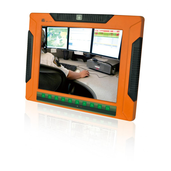
Figure 1-1: UPC-V315-QM77 Panel PC The fanless UPC-V315-QM77 is Intel® Core™ i3-3217UE/i7-3517UE processor powered panel PC with a rich variety of functions and peripherals. The UPC-V315-QM77 panel PC is designed for easy and simplified integration into various vehicle applications. An Intel® mobile QM77 express chipset ensures optimal memory, graphics, and peripheral I/O support. -
Page 15: Model Variations
1.4.1 Fro n t P a n e l The front side of the UPC-V315-QM77 is a flat panel TFT LCD screen surrounded by an aluminum frame. At the top of the front panel features one 2.0 megapixel webcam that... -
Page 16: Led Indicators
Audio mute LED Sensors Ambient light sensor Infrared remote control sensor Figure 1-2: Front View 1.4.1.1 LED In d ic a to rs The LED indicators on the front panel of the UPC-V315-QM77 are shown below. P a g e 4... -
Page 17: Figure 1-3: Led Indicators
UP C-V315-QM77 P a ne l P C Figure 1-3: LED Indicators The descriptions of each LED indicator are listed below. LED Indicator Description Power 1 Pulsing Orange: Power 1 is the main power and is in standby mode Solid Orange: Power 1 is the second power and is in standby mode Solid Blue: Power 1 is providing power to the system Power 2 Pulsing Orange: Power 2 is the main power and is in standby mode... -
Page 18: Bottom Panel
CPU. 1.4.2 Bo tto m P a n e l The following is a list of the bottom panel peripheral device connectors on the UPC-V315-QM77. 1 x 9 V ~ 36 V DC power input terminal block (Power I) ... -
Page 19: Side Panels
UP C-V315-QM77 P a ne l P C 1 x ACC on/off switch 1 x AT/ATX power mode switch 1 x Clear CMOS switch 1 x Reset button Figure 1-4: Bottom View 1.4.3 S id e P a n e ls The left side panel of the panel PC provides access to the SSD dive bay. -
Page 20: Rear Panel
1.4.5 Fra m e (Fu n c tio n Ke ys ) An aluminum frame surrounds the TFT LCD screen. The aluminum frame of the UPC-V315-QM77 contains several function keys that control audio volume, LCD brightness and some other system components. -
Page 21: Figure 1-8: Function Key Locations
UP C-V315-QM77 P a ne l P C Figure 1-8: Function Key Locations The following table describes the function of these function keys. Buttons Function Buttons Function Function LCD on/off Audio volume down Mute audio Audio volume up Enable/Disable webcam Brightness up Brightness down Power on/off... -
Page 22: Dimensions
UP C-V315-QM77 P a ne l P C 1.5 Dim e n s io n s The dimensions of the UPC-V315-QM77 are shown in Figure 1-9 and listed below. Figure 1-9: UPC-V315-QM77 Dimensions (mm) P a g e 10... -
Page 23: Specifications
UP C-V315-QM77 P a ne l P C 1.6 Sp e c ific a tio n s The technical specifications for the UPC-V315-QM77 system are listed in Table 1-3. Specification UPC-V315-QM77 Display LCD Size 15” Max. Resolution 1024(W) x 768(H) Brightness (cd/m²) - Page 24 UP C-V315-QM77 P a ne l P C System Audio AMP 3W + 3W (Internal Speaker) Camera 2M Mega Pixels Connectivity Wireless IEEE 802.11a/b/g/n 3T3R module (WIFI-RT5393-DB-R10) Drive Bay HDD Driver Bay 1 x 2.5” SATA SSD mSATA CD-ROM Driver Bay Expansion Slot 1 x PCIe Mini Card System Cooling...
-
Page 25: Table 1-3: System Specifications
UP C-V315-QM77 P a ne l P C Power Adapter 90 W; 63040-010090-020-RS Requirement Power1:9V~36V(+/-0.3V) Power2:10.5V~36V(+/-0.3V) I/O Ports and Switches 3 x RS-232 (RJ-45) 1 x RS-422/485 (RJ-45) 1 x CAN-BUS 1 x VGA 1 x HDMI port 2 x GbE LAN 2 x USB 2.0 2 x USB 3.0 1 x Reset button... -
Page 26: Unpacking
UP C-V315-QM77 P a ne l P C Chapter Un p a c kin g P a g e 14... -
Page 27: Unpacking
UP C-V315-QM77 P a ne l P C 2.1 Un pa c kin g To unpack the panel PC, follow the steps below: WARNING! The front side LCD screen has a protective plastic cover stuck to the screen. Only remove the plastic cover after the panel PC has been properly installed. -
Page 28: Packing List
UP C-V315-QM77 P a ne l P C 2.2 P a c kin g Lis t The UPC-V315-QM77 panel PC is shipped with the following components: Qu a n tity Ite m Im a g e UPC-V315-QM77 panel PC Power adapter... - Page 29 UP C-V315-QM77 P a ne l P C VESA mount screw (M4) (P/N: 44005-040082-RS) Mounting bracket (side panels) (P/N: 41003-0382C2-00-RS) Screw driver (P/N: 45019-001004-00) One Key Recover CD Utility CD If any of these items are missing or damaged, contact the distributor or sales representative immediately.
-
Page 30: Installation
UP C-V315-QM77 P a ne l P C Chapter In s ta lla tio n P a g e 18... -
Page 31: Anti - Static Precautions
Electrostatic discharge (ESD) can cause serious damage to electronic components, including the UPC-V315-QM77. Dry climates are especially susceptible to ESD. It is therefore critical that whenever the UPC-V315-QM77 is accessed internally, or any other electrical component is handled, the following anti-static precautions are strictly adhered ... -
Page 32: Preinstalled Components
Webcam CAUTION: The UPC-V315-QM77 is an IP 65 compliant panel PC. A user cannot open the rear cover and install any components inside the UPC-V315-QM77. Doing so may compromise the system’s waterproof performance. To install components in the system, please contact the system vendor, reseller or an IEI sales person directly. -
Page 33: Figure 3-1: Remove The Ssd Drive Bay Access Panel
UP C-V315-QM77 P a ne l P C NOTE: Please use the screw driver that comes with the UPC-V315-QM77 to remove the screws on the chassis. Figure 3-1: Remove the SSD Drive Bay Access Panel S te p 3: Insert the SSD into the bracket as shown. -
Page 34: Figure 3-3: Securing The Ssd
UP C-V315-QM77 P a ne l P C Figure 3-3: Securing the SSD S te p 5: Install the SSD. Correctly align the SSD bracket with the system and insert the SSD bracket into the system. Figure 3-4: SSD Installation Reinstall the SSD drive bay access panel. -
Page 35: Mounting The System
Figure 3-5: VESA Mount Retention Screw Holes To enhance the stability, the user can use the mounting brackets, which are shipped with the UPC-V315-QM77 and can be attached on both side panels. An additional mounting device is required for the mounting brackets. -
Page 36: Wall Mounting
Figure 3-6: Mounting Brackets (Side Panels) NOTE: When mounting the UPC-V315-QM77 on a vehicle, it is recommended to use the M8 mounting screws on the real panel. A special mounting bracket is required for M8 mounting screw. Please contact IEI for more information. -
Page 37: Figure 3-7: Wall-Mounting Bracket
UP C-V315-QM77 P a ne l P C Figure 3-7: Wall-mounting Bracket S te p 6: Insert the four monitor mounting screws provided in the wall mounting kit into the four screw holes on the real panel of the flat panel PC and tighten until the screw shank is secured against the rear panel (Figure 3-8). -
Page 38: Figure 3-8: Chassis Support Screws
UP C-V315-QM77 P a ne l P C Figure 3-8: Chassis Support Screws NOTE: In the diagram below the bracket is already installed on the wall. S te p 9: Secure the panel PC by fastening the retention screw of the wall-mounting bracket. -
Page 39: Bottom Panel Connectors
3.6 Bo tto m P a n e l Co n n e c to rs The bottom panel of the UPC-V315-QM77 contains I/O connectors, switches and a reset button. These connectors are protected by an I/O cover. Detailed descriptions of the connectors can be found in the subsections below. -
Page 40: Figure 3-10: I/O Cover Retention Screws
Figure 3-10: I/O Cover Retention Screws S te p 2: Connect the cable from the external peripheral device to the corresponding connector of the UPC-V315-QM77 (Figure 3-11). Figure 3-11: External Peripheral Device Connection Take out a rubber gasket from the I/O cover (Figure 3-12). -
Page 41: Acc Mode Selection
3.6.3 AT/ATX P owe r Mo d e S e le c tio n The UPC-V315-QM77 supports both AT and ATX power modes. The setting can be made through the AT/ATX power mode switch on the bottom panel as shown below. -
Page 42: Audio Connectors
3.6.6 HDMI Co n n e c to r The HDMI connector transmits a digital signal to compatible HDMI display devices such as a TV or computer screen. To connect the HDMI cable to the UPC-V315-QM77, follow the steps below. -
Page 43: Figure 3-18: Hdmi Connection
UP C-V315-QM77 P a ne l P C Figure 3-18: HDMI Connection S te p 3: Insert the HDMI connector. Gently insert the HDMI connector. The connector should engage with a gentle push. If the connector does not insert easily, check again that the connector is aligned correctly, and that the connector is being inserted with the right way up. -
Page 44: Lan Connector
UP C-V315-QM77 P a ne l P C 3.6.7 LAN Co n n e c to r To connect the UPC-V315-QM77 to a network through the RJ-45 LAN connector, follow the steps below. S te p 1: Locate the RJ-45 connector. The location of the RJ-45 connectors is shown in Figure 1-4. -
Page 45: Power Input, 3-Pin Terminal Block
UP C-V315-QM77 P a ne l P C The pinouts of the RJ-45 LAN connector is shown below. Description Description MDI0+ MDI0- MDI1+ MDI1- MDI2+ MDI2- MDI3+ MDI3- Table 3-2: LAN Pinouts The RJ-45 Ethernet connector has two status LEDs, one green and one yellow. See Figure 3-20. -
Page 46: Rs-232 Serial Port
UP C-V315-QM77 P a ne l P C Figure 3-22: Power Input Connector 3.6.10 RJ -45 RS -232 S e ria l P o rt RS-232 serial port devices can be attached to the RJ-45 RS-232 serial ports on the bottom panel. -
Page 47: Figure 3-25: Rj-45 Rs-232 Serial Device Connection
Figure 1-4. Insert the RJ-45 connector. Insert the RJ-45 connector on the RJ-45 to DB-9 S te p 2: COM port cable to the RJ-45 RS-232 connector on the UPC-V315-QM77. See Figure 3-25. Figure 3-25: RJ-45 RS-232 Serial Device Connection Insert the serial connector. -
Page 48: Rs-422/485 Serial Port
UP C-V315-QM77 P a ne l P C 3.6.11 RJ -45 RS -422/485 S e ria l P o rt A RS-422/485 serial port device can be connected to the RS-422/485 serial port on the bottom panel. The pinouts of the RS-422/485 serial port is shown below. Figure 3-26: RJ-45 RS-422/485 Serial Port Pinout Location Description Description... -
Page 49: Usb Connectors
RS-422/485 connector is shown in Figure 1-4. Insert the RJ-45 connector. Insert the RJ-45 connector on the RJ-45 to DB-9 S te p 2: COM port cable to the RJ-45 RS-422/485 connector on the UPC-V315-QM77. See Figure 3-25. Figure 3-28: RJ-45 RS-422/485 Serial Device Connection Insert the serial connector. -
Page 50: Figure 3-29: Usb Device Connection
UP C-V315-QM77 P a ne l P C Figure 3-29: USB Device Connection Insert the device connector. Once aligned, gently insert the USB device S te p 3: connector into the on-board connector. The pinouts of the USB ports are shown below. Description Description USB_PN0... -
Page 51: Vga Connector
Figure 3-30: VGA Connector Description Description GREEN BLUE VCC / NC DDC DAT HSYNC VSYNC DDCCLK Table 3-10: VGA Connector Pinouts To connect the UPC-V315-QM77 to a monitor that accepts VGA video input, follow the steps below, P a g e 39... -
Page 52: Figure 3-31: Vga Connector
Once the connectors are properly aligned with the S te p 3: insert the male connector from the VGA screen into the female connector on the UPC-V315-QM77. See Figure 3-31. Figure 3-31: VGA Connector CAUTION: It is suggested that not to open the rear cover and replace any components. -
Page 53: Redundant Power
UP C-V315-QM77 P a ne l P C 3.7 Re d u n d a n t P owe r The UPC-V315-QM77 is a system that supports redundant power. The redundant power input increases the reliability of the system while preventing data loss and system corruption from sudden power failure. -
Page 54: Acc On
In ACC On mode, the Power 1 connector must connect to the ACC on signal to be able to control system power. The ACC On mode is designed for vehicle applications. When the UPC-V315-QM77 is in ACC On mode, the main power input is the Power 1 connector and the backup power is from the Power 2 connector. -
Page 55: Switch To Backup Power
UP C-V315-QM77 P a ne l P C 3.7.1.2 S witc h to Ba c ku p P owe r During operation, system power will switch from Power 1 to Power 2 automatically when the following situations occur: Power 1 < 9V and Power 2 > 10.5V ... -
Page 56: Acc Off
Press these two buttons for six seconds to turn off the system. 3.7.2 ACC OFF When the UPC-V315-QM77 is in ACC Off mode, the main power input is the Power 2 connector and the backup power is from the Power 1 connector. 3.7.2.1 Bo o t-u p When both power connectors are connected to the power source with over 9 V, the two power LEDs on the front panel turn on. -
Page 57: Switch To Backup Power
UP C-V315-QM77 P a ne l P C Figure 3-37: ACC Off: AT Mode Figure 3-38: ACC Off: ATX Mode 3.7.2.2 S witc h to Ba c ku p P owe r During operation, system power switches from Power 2 to Power 1 automatically when the following situations occur: ... -
Page 58: Shutdown
UP C-V315-QM77 P a ne l P C 3.7.2.3 S h u td own The system will shutdown in the following situations: Power 2 < 10.5V and Power 1 < 9V Press buttons for 6 seconds The following flow diagram shows the system shutdown process and the LED statuses. Figure 3-40: ACC Off: Shutdown NOTE: The power LED turns off when the power cable is unplugged from the... -
Page 59: Remote Control
UP C-V315-QM77 P a ne l P C 3.8 Re m o te Co n tro l The UPC-V315-QM77 comes with a remote control for easy configuration. Figure 3-41 shows the remote control and its function keys. Figure 3-41: Remote Control ... -
Page 60: Bios
UP C-V315-QM77 P a ne l P C Chapter BIOS P a g e 48... -
Page 61: Introduction
UP C-V315-QM77 P a ne l P C 4.1 In tro d u c tio n The BIOS is programmed onto the BIOS chip. The BIOS setup program allows changes to certain system settings. This chapter outlines the options that can be changed. 4.1.1 Sta rtin g S e tu p The UEFI BIOS is activated when the computer is turned on. -
Page 62: Getting Help
UP C-V315-QM77 P a ne l P C Ke y Fu n c tio n Esc key Main Menu – Quit and not save changes into CMOS Status Page Setup Menu and Option Page Setup Menu -- Exit current page and return to Main Menu General help, only for Status Page Setup Menu and Option Page Setup Menu Load previous values... -
Page 63: Main
UP C-V315-QM77 P a ne l P C 4.2 Ma in The Main BIOS menu (BIOS Menu 1) appears when the BIOS Setup program is entered. The Main menu gives an overview of the basic system information. Aptio Setup Utility – Copyright (C) 2011 American Megatrends, Inc. Main Advanced Chipset... -
Page 64: Advanced
UP C-V315-QM77 P a ne l P C S ys te m Ove rvie w The system overview lists a brief summary of the BIOS. The fields in system overview cannot be changed. The items shown in the system overview include: ... -
Page 65: Acpi Settings
UP C-V315-QM77 P a ne l P C Aptio Setup Utility – Copyright (C) 2011 American Megatrends, Inc. Main Advanced Chipset Boot Security Save & Exit > ACPI Settings System ACPI Parameters > RTC Wake Settings > CPU Configuration > SATA Configuration >... -
Page 66: Rtc Wake Settings
UP C-V315-QM77 P a ne l P C ACP I S le e p Sta te [S 1 (CP U Sto p Clo c k)] Use the ACPI Sleep State option to specify the sleep state the system enters when it is not being used. -
Page 67: Cpu Configuration
UP C-V315-QM77 P a ne l P C Wa ke s ys te m with Fixe d Tim e [Dis a b le d ] Use the Wake system with Fixed Time option to enable or disable the system wake on alarm event. - Page 68 UP C-V315-QM77 P a ne l P C Aptio Setup Utility – Copyright (C) 2011 American Megatrends, Inc. Advanced CPU Configuration Enabled for Windows XP and Linux (OS optimized Intel(R) Core(TM) i3-3217UE CPU @ 1.60GHz for Hyper-Threading CPU Signature 306a9 Technology) and Disabled Microcode Patch for other OS (OS not...
-
Page 69: Sata Configuration
UP C-V315-QM77 P a ne l P C 4.3.4 S ATA Co n fig u ra tio n Use the SATA Configuration menu (BIOS Menu 6) to change and/or set the configuration of the SATA devices installed in the system. Aptio Setup Utility –... -
Page 70: Usb Configuration
UP C-V315-QM77 P a ne l P C Aptio Setup Utility – Copyright (C) 2011 American Megatrends, Inc. Advanced Intel(R) Rapid Start Technology [Disabled] --------------------- : Select Screen ↑ ↓: Select Item Enter: Select +/-: Change Opt. General Help Previous Values Optimized Defaults Save &... -
Page 71: F81866 Super Io Configuration
UP C-V315-QM77 P a ne l P C US B De vic e s The USB Devices field lists the USB devices that are enabled on the system Le g a c y US B S u p p o rt [En a b le d ] Use the Legacy USB Support BIOS option to enable USB mouse and USB keyboard support. -
Page 72: Serial Port N Configuration
UP C-V315-QM77 P a ne l P C 4.3.7.1 S e ria l P o rt n Co n fig u ra tio n Use the Serial Port n Configuration menu (BIOS Menu 10) to configure the serial port n. Aptio Setup Utility –... - Page 73 UP C-V315-QM77 P a ne l P C Serial Port I/O port address is 3F8h and the interrupt IO=3F8h; IRQ=3, 4 address is IRQ3, 4 IO=2F8h; Serial Port I/O port address is 2F8h and the interrupt address is IRQ3, 4 IRQ=3, 4 4.3.7.1.2 S e ria l P o rt 2 Co n fig u ra tio n ...
- Page 74 UP C-V315-QM77 P a ne l P C Enable the serial port Enabled EFAULT Ch a n g e S e ttin g s [Au to ] Use the Change Settings option to change the serial port IO port address and interrupt address.
-
Page 75: H/W Monitor
UP C-V315-QM77 P a ne l P C Serial Port I/O port address is 2E0h and the interrupt IO=2E0h; IRQ=5, 7 address is IRQ5, 7 IO=2E8h; Serial Port I/O port address is 2E8h and the interrupt address is IRQ5, 7 IRQ=5, 7 ... -
Page 76: Serial Port Console Redirection
UP C-V315-QM77 P a ne l P C System Temperature Voltages: V_CORE V_5S V_12S V_1.5V VSB5V VCC3V VSB3V 4.3.9 S e ria l P o rt Co n s o le Re d ire c tio n The Serial Port Console Redirection menu (BIOS Menu 12) allows the console redirection options to be configured. - Page 77 UP C-V315-QM77 P a ne l P C Enabled the console redirection function Enabled Te rm in a l Typ e [ANS I] Use the Terminal Type option to specify the remote terminal type. VT100 The target terminal type is VT100 ...
-
Page 78: Iei Feature
UP C-V315-QM77 P a ne l P C No parity bit is sent with the data bits. None EFAULT Even The parity bit is 0 if the number of ones in the data bits is even. The parity bit is 0 if the number of ones in the data bits is odd. - Page 79 UP C-V315-QM77 P a ne l P C Aptio Setup Utility – Copyright (C) 2011 American Megatrends, Inc. Advanced iEi Feature Auto Recovery Function Reboot and recover Auto Recovery Function [Disabled] system automatically within 10 min, when OS crashes. Please install Auto Recovery API service before enabling this function.
-
Page 80: Chipset
UP C-V315-QM77 P a ne l P C 4.4 Ch ips e t Use the Chipset menu (BIOS Menu 14) to access the PCH IO and System Agent (SA) configuration menus. WARNING! Setting the wrong values for the Chipset BIOS selections in the Chipset BIOS menu may cause the system to malfunction. -
Page 81: Pch-Io Configuration
UP C-V315-QM77 P a ne l P C 4.4.1 P CH-IO Co n fig u ra tio n Use the PCH-IO Configuration menu (BIOS Menu 15) to configure the PCH parameters. Aptio Setup Utility – Copyright (C) 2011 American Megatrends, Inc. Chipset Auto Power Button Status [Disabled (AT)]... -
Page 82: Pch Azalia Configuration
UP C-V315-QM77 P a ne l P C Disables auto dimming function Disabled EFAULT P o we r S a vin g Fu n c tio n [Dis a b le d ] Use the Power Saving Function BIOS option to enable or disable the power saving function. -
Page 83: System Agent (Sa) Configuration
UP C-V315-QM77 P a ne l P C Aza lia in te rn a l HDMI c o d e c [En a b le d ] Use the Azalia internal HDMI codec option to enable or disable the internal HDMI codec for High Definition Audio. - Page 84 UP C-V315-QM77 P a ne l P C Aptio Setup Utility – Copyright (C) 2011 American Megatrends, Inc. Chipset Graphics Configuration Select DVMT 5.0 Pre-Allocated (Fixed) DVMT Pre-Allocated [256M] Graphics Memory size DVMT Total Gfx Mem [MAX] used by the Internal >...
- Page 85 UP C-V315-QM77 P a ne l P C 4.4.2.1.1 LCD Co n tro l Aptio Setup Utility – Copyright (C) 2011 American Megatrends, Inc. Chipset LCD Control Select the Video Device which will be activated Primary IGFX Boot Display [VBIOS Default] during POST.
-
Page 86: Nb Pcie Configuration
UP C-V315-QM77 P a ne l P C 800x600 LVDS 1024x768 LVDS1 1280x1024 LVDS 1400x1050(RB) LVDS1 1400x1050 LVDS2 1600x1200 LVDS 1366x768 LVDS 1680x1050 LVDS 1920x1200 LVDS 1440x900 LVDS 1600x1200 LVDS ... -
Page 87: Memory Configuration
UP C-V315-QM77 P a ne l P C Auto Default Gen1 Gen2 Gen3 4.4.2.3 Me m o ry Co n fig u ra tio n Use the Memory Configuration submenu (BIOS Menu 21) to view memory information. Aptio Setup Utility –... -
Page 88: Boot
UP C-V315-QM77 P a ne l P C 4.5 Bo o t Use the Boot menu (BIOS Menu 22) to configure system boot options. Aptio Setup Utility – Copyright (C) 2011 American Megatrends, Inc. Main Advanced Chipset Boot Security Save & Exit Boot Configuration Select the keyboard Bootup NumLock State... - Page 89 UP C-V315-QM77 P a ne l P C Qu ie t Bo o t [En a b le d ] Use the Quiet Boot BIOS option to select the screen display when the system boots. Normal POST messages displayed Disabled ...
-
Page 90: Security
UP C-V315-QM77 P a ne l P C 4.6 S e c u rity Use the Security menu (BIOS Menu 23) to set system and user passwords. Aptio Setup Utility – Copyright (C) 2011 American Megatrends, Inc. Main Advanced Chipset Boot Security Save &... -
Page 91: Save & Exit
UP C-V315-QM77 P a ne l P C 4.7 S a ve & Exit Use the Safe & Exit menu (BIOS Menu 24) to load default BIOS values, optimal failsafe values and to save configuration changes. Aptio Setup Utility – Copyright (C) 2011 American Megatrends, Inc. Main Advanced Chipset... - Page 92 UP C-V315-QM77 P a ne l P C S a ve a s Us e r De fa u lts Use the Save as User Defaults option to save the changes done so far as user defaults. Re s to re Us e r De fa u lts Use the Restore User Defaults option to restore the user defaults to all the setup options.
-
Page 93: A Bios Menu Options
UP C-V315-QM77 P a ne l P C Appendix BIOS Me n u Op tio n s P a g e 81... - Page 94 UP C-V315-QM77 P a ne l P C System Overview .........................52 System Date [xx/xx/xx] ......................52 System Time [xx:xx:xx] .......................52 ACPI Sleep State [S1 (CPU Stop Clock)] ................54 Wake system with Fixed Time [Disabled] ................55 Hyper-threading [Enabled] ....................56 ...
- Page 95 UP C-V315-QM77 P a ne l P C DVMT Total Gfx Mem [MAX] ....................72 Primary IGFX Boot Display [VBIOS] ..................73 LCD Panel Type [VBIOS] .....................73 PEG0 – Gen X [Auto] ......................74 Bootup NumLock State [On] ....................76 ...
-
Page 96: B One Key Recovery
UP C-V315-QM77 P a ne l P C Ap p e n d ix On e Ke y Re c o ve ry P a g e 84... -
Page 97: One Key Recovery Introduction
UP C-V315-QM77 P a ne l P C B.1 On e Ke y Re c o ve ry In tro d u c tio n The IEI one key recovery is an easy-to-use front end for the Norton Ghost system backup and recovery tool. -
Page 98: System Requirement
UP C-V315-QM77 P a ne l P C After completing the five initial setup procedures as described above, users can access the recovery tool by pressing <F3> while booting up the system. The detailed information of each function is described in Section B.5. NOTE: The initial setup procedures for Linux system are described in Section B.3. -
Page 99: Supported Operating System
UP C-V315-QM77 P a ne l P C partitions. Please take the following table as a reference when calculating the size of the partition. OS Image after Ghost Compression Ratio Windows® 7 7 GB 5 GB Windows® XPE 776 MB 560 MB Windows®... -
Page 100: Setup Procedure For Windows
UP C-V315-QM77 P a ne l P C Ubuntu 8.10 (Intrepid) Ubuntu 7.10 (Gutsy) Ubuntu 6.10 (Edgy) Debian 5.0 (Lenny) Debian 4.0 (Etch) SuSe 11.2 SuSe 10.3 NOTE: Installing unsupported OS versions may cause the recovery tool to fail. B.2 S e tu p P ro c e d u re fo r Win d ows Prior to using the recovery tool to backup or restore, a few setup procedures are required. -
Page 101: Hardware And Bios Setup
UP C-V315-QM77 P a ne l P C B.2.1 Ha rdwa re a n d BIOS S e tu p Make sure the system is powered off and unplugged. S te p 1: Install a hard drive or SSD in the system. An unformatted and unpartitioned disk S te p 2: is recommended. -
Page 102: Figure B-2: Launching The Recovery Tool
UP C-V315-QM77 P a ne l P C Figure B-2: Launching the Recovery Tool S te p 3: The recovery tool setup menu is shown as below. Figure B-3: Recovery Tool Setup Menu S te p 4: Press <6> then <Enter>. P a g e 90... -
Page 103: Figure B-4: Command Prompt
UP C-V315-QM77 P a ne l P C Figure B-4: Command Prompt S te p 5: The command prompt window appears. Type the following commands (marked in red) to create two partitions. One is for the OS installation; the other is for saving recovery files and images which will be an invisible partition. -
Page 104: Figure B-5: Partition Creation Commands
UP C-V315-QM77 P a ne l P C Figure B-5: Partition Creation Commands P a g e 92... -
Page 105: Install Operating System, Drivers And Applications
UP C-V315-QM77 P a ne l P C NOTE: Use the following commands to check if the partitions were created successfully. S te p 6: Press any key to exit the recovery tool and automatically reboot the system. Please continue to the following procedure: Build the Recovery Partition.S t e p 0 : B.2.3 In s ta ll Op e ra tin g S ys te m , Drive rs a n d Ap p lic a tio n s Install the operating system onto the unlabelled partition. -
Page 106: Building The Recovery Partition
UP C-V315-QM77 P a ne l P C B.2.4 Bu ild in g th e Re c o ve ry P a rtitio n Put the recover CD in the optical drive. S te p 1: Start the system. S te p 2: S te p 3: Boot the system from the recovery CD. -
Page 107: Figure B-8: Building The Recovery Partition
UP C-V315-QM77 P a ne l P C S te p 5: The Symantec Ghost window appears and starts configuring the system to build a recovery partition. In this process the partition created for recovery files in Section B.2.2 is hidden and the recovery tool is saved in this partition. Figure B-8: Building the Recovery Partition After completing the system configuration, press any key in the following window S te p 6:... -
Page 108: Create Factory Default Image
UP C-V315-QM77 P a ne l P C B.2.5 Cre a te Fa c to ry De fa u lt Im a g e NOTE: Before creating the factory default image, please configure the system to a factory default environment, including driver and application installations. -
Page 109: Figure B-12: About Symantec Ghost Window
UP C-V315-QM77 P a ne l P C Figure B-12: About Symantec Ghost Window Use mouse to navigate to the option shown below (Figure B-13). S te p 4: Figure B-13: Symantec Ghost Path S te p 5: Select the local source drive (Drive 1) as shown in Figure B-14. Then click OK. P a g e 97... -
Page 110: Figure B-14: Select A Local Source Drive
UP C-V315-QM77 P a ne l P C Figure B-14: Select a Local Source Drive S te p 6: Select a source partition (Part 1) from basic drive as shown in Figure B-15. Then click OK. Figure B-15: Select a Source Partition from Basic Drive Select 1.2: [Recovery] NTFS drive and enter a file name called S te p 7: (Figure B-16). -
Page 111: Figure B-16: File Name To Copy Image To
UP C-V315-QM77 P a ne l P C Figure B-16: File Name to Copy Image to When the Compress Image screen in Figure B-17 prompts, click High to make S te p 8: the image file smaller. Figure B-17: Compress Image P a g e 99... -
Page 112: Figure B-18: Image Creation Confirmation
UP C-V315-QM77 P a ne l P C The Proceed with partition image creation window appears, click Yes to S te p 9: continue. Figure B-18: Image Creation Confirmation The Symantec Ghost starts to create the factory default image (Figure B-19). S te p 10: Figure B-19: Image Creation Complete When the image creation completes, a screen prompts as shown in Figure B-20. -
Page 113: Auto Recovery Setup Procedure
UP C-V315-QM77 P a ne l P C S te p 12: The recovery tool main menu window is shown as below. Press any key to reboot the system. S t e p 0 : Figure B-21: Press Any Key to Continue B.3 Au to Re c o ve ry S e tu p P ro c e d u re The auto recovery function allows a system to automatically restore from the factory default image after encountering a Blue Screen of Death (BSoD) or a hang for around 10... -
Page 114: Figure B-22: Auto Recovery Utility
UP C-V315-QM77 P a ne l P C Figure B-22: Auto Recovery Utility Reboot the system from the recovery CD. When prompted, press any key to S te p 3: boot from the recovery CD. It will take a while to launch the recovery tool. Please be patient! Figure B-23: Launching the Recovery Tool S te p 4:... -
Page 115: Figure B-25: Building The Auto Recovery Partition
UP C-V315-QM77 P a ne l P C S te p 5: The Symantec Ghost window appears and starts configuring the system to build an auto recovery partition. In this process the partition created for recovery files in Section B.2.2 is hidden and the auto recovery tool is saved in this partition. Figure B-25: Building the Auto Recovery Partition After completing the system configuration, the following message prompts to S te p 6:... -
Page 116: Figure B-27: Image Creation Complete
UP C-V315-QM77 P a ne l P C The Symantec Ghost starts to create the factory default image (Figure B-27). S te p 7: Figure B-27: Image Creation Complete S te p 8: After completing the system configuration, press any key in the following window to restart the system. -
Page 117: Setup Procedure For Linux
UP C-V315-QM77 P a ne l P C BIOS SETUP UTILITY Main Advanced PCIPNP Boot Security Chipset Exit iEi Feature Auto Recovery Function [Enabled] Recover from PXE [Disabled] Select Screen ↑ ↓ Select Item Enter Go to SubScreen General Help Save and Exit Exit... -
Page 118: Figure B-29: Partitions For Linux
UP C-V315-QM77 P a ne l P C Install Linux operating system. Make sure to install GRUB (v0.97 or earlier) S te p 2: MBR type and Ext3 partition type. Leave enough space on the hard drive to create the recover partition later. NOTE: If the Linux OS is not installed with GRUB (v0.97 or earlier) and Ext3, the Symantec Ghost may not function properly. -
Page 119: Figure B-30: Manual Recovery Environment For Linux
UP C-V315-QM77 P a ne l P C DISKPART>create part pri size= DISKPART>assign letter=N DISKPART>exit system32>format N: /fs:ntfs /q /v:Recovery /y system32>exit Build the recovery partition. Press any key to boot from the recovery CD. It will S te p 4: take a while to launch the recovery tool. -
Page 120: Figure B-31: Access Menu.lst In Linux (Text Mode)
UP C-V315-QM77 P a ne l P C Figure B-31: Access menu.lst in Linux (Text Mode) Modify the menu.lst as shown below. S te p 6: The recovery tool menu appears. (Figure B-32) S te p 7: Figure B-32: Recovery Tool Menu Create a factory default image. -
Page 121: Recovery Tool Functions
UP C-V315-QM77 P a ne l P C B.5 Re c o ve ry To o l Fu n c tio n s After completing the initial setup procedures as described above, users can access the recovery tool by pressing <F3> while booting up the system. However, if the setup procedure in Section B.3 has been completed and the auto recovery function is enabled, the system will automatically restore from the factory default image without pressing the F3 key. -
Page 122: Factory Restore
UP C-V315-QM77 P a ne l P C WARNING: All data in the system will be deleted during the system recovery. Please backup the system files before restoring the system (either Factory Restore or Restore Backup). B.5.1 Fa c to ry Re s to re To restore the factory default image, please follow the steps below. -
Page 123: Backup System
UP C-V315-QM77 P a ne l P C Figure B-35: Recovery Complete Window B.5.2 Ba c ku p S ys te m To backup the system, please follow the steps below. Type <2> and press <Enter> in the main menu. S te p 1: The Symantec Ghost window appears and starts to backup the system. -
Page 124: Restore Your Last Backup
UP C-V315-QM77 P a ne l P C Figure B-37: System Backup Complete Window B.5.3 Re s to re Yo u r La s t Ba c ku p To restore the last system backup, please follow the steps below. Type <3>... -
Page 125: Manual
UP C-V315-QM77 P a ne l P C Figure B-39: Restore System Backup Complete Window B.5.4 Ma n u a l To restore the last system backup, please follow the steps below. Type <4> and press <Enter> in the main menu. S te p 1: The Symantec Ghost window appears. -
Page 126: Restore Systems From A Linux Server Through Lan
UP C-V315-QM77 P a ne l P C B.6 Re s to re S ys te m s fro m a Lin u x S e rve r thro u g h LAN The One Key Recovery allows a client system to automatically restore to a factory default image saved in a Linux system (the server) through LAN connectivity after encountering a Blue Screen of Death (BSoD) or a hang for around 10 minutes. -
Page 127: Configure Dhcp Server Settings
UP C-V315-QM77 P a ne l P C B.6.1 Co n fig u re DHCP S e rve r S e ttin g s Install the DHCP S te p 1: #yum install dhcp (CentOS, commands marked in red) #apt-get install dhcp3-server (Debian, commands marked in blue) Confirm the operating system default settings: dhcpd.conf. -
Page 128: Configure Tftp Settings
UP C-V315-QM77 P a ne l P C filename “pxelinux.0”; B.6.2 Co n fig u re TFTP S e ttin g s S te p 1: Install the tftp, httpd and syslinux. #yum install tftp-server httpd syslinux (CentOS) #apt-get install tftpd-hpa xinetd syslinux (Debian) S te p 2: Enable the TFTP server by editing the “/etc/xinetd.d/tftp”... -
Page 129: Configure One Key Recovery Server Settings
UP C-V315-QM77 P a ne l P C Debian Replace the TFTP settings from “inetd” to “xinetd” and annotate the “inetd” by adding “#”. #vi /etc/inetd.conf Modify: #tftp dgram udp wait root /usr/sbin..(as shown below) #vi /etc/xinetd.d/tftp B.6.3 Co n fig u re On e Ke y Re c o ve ry S e rve r S e ttin g s Copy the Utility/RECOVERYR10.TAR.BZ2 package from the One Key S te p 1: Recovery CD to the system (server side). -
Page 130: Start The Dhcp, Tftp And Http
UP C-V315-QM77 P a ne l P C B.6.4 Sta rt th e DHCP, TFTP a n d HTTP Start the DHCP, TFTP and HTTP. For example: CentOS #service xinetd restart #service httpd restart #service dhcpd restart Debian #/etc/init.d/xinetd reload #/etc/init.d/xinetd restart #/etc/init.d/dhcp3-server restart B.6.5 Cre a te S ha re d Dire c to ry... -
Page 131: Setup A Client System For Auto Recovery
UP C-V315-QM77 P a ne l P C Modify: [image] comment = One Key Recovery path = /share/image browseable = yes writable = yes public = yes create mask = 0644 directory mask = 0755 S te p 4: Edit “/etc/samba/smb.conf” for your environment. For example: Modify the hostname S te p 5: #vi /etc/hostname... - Page 132 UP C-V315-QM77 P a ne l P C Continue to configure the Boot Option Priorities BIOS option of the client S te p 2: system: Boot Option #1 remain the default setting to boot from the original OS. Boot Option #2 select the boot from LAN option. Save changes and exit BIOS menu.
- Page 133 UP C-V315-QM77 P a ne l P C NOTE: A firewall or a SELinux is not in use in the whole setup process. If there is a firewall or a SELinux protecting the system, modify the configuration information to accommodate them. P a g e 121...
-
Page 134: Other Information
UP C-V315-QM77 P a ne l P C B.7 Oth e r In fo rm a tio n B.7.1 Us in g AHCI Mo d e o r ALi M5283 / VIA VT6421A Co n tro lle r When the system uses AHCI mode or some specific SATA controllers such as ALi M5283 or VIA VT6421A, the SATA RAID/AHCI driver must be installed before using one key recovery. - Page 135 UP C-V315-QM77 P a ne l P C When the following window appears, press <S> to select “Specify Additional S te p 5: Device”. In the following window, select a SATA controller mode used in the system. Then S te p 6: press <Enter>.
-
Page 136: System Memory Requirement
UP C-V315-QM77 P a ne l P C S te p 7: After pressing <Enter>, the system will get into the recovery tool setup menu. Continue to follow the setup procedure from Step 4 in Section B.2.2 Create Partitions to finish the whole setup process. S t e p 0 : B.7.2 S ys te m Me m o ry Re q u ire m e n t To be able to access the recovery tool by pressing <F3>... -
Page 137: C Safety Precautions
UP C-V315-QM77 P a ne l P C Appendix S a fe ty P re c a u tio n s P a g e 125... -
Page 138: Safety Precautions
UP C-V315-QM77 P a ne l P C WARNING: The precautions outlined in this chapter should be strictly followed. Failure to follow these precautions may result in permanent damage to the UPC series. C.1 S a fe ty P re c a u tio n s Please follow the safety precautions outlined in the sections that follow: C.1.1 Ge n e ra l S a fe ty P re c a u tio n s Please ensure the following safety precautions are adhered to at all times. -
Page 139: Anti-Static Precautions
UP C-V315-QM77 P a ne l P C C.1.2 An ti-s ta tic P re c a u tio n s WARNING: Failure to take ESD precautions during the installation of the UPC series may result in permanent damage to the UPC series and severe injury to the user. -
Page 140: Maintenance And Cleaning Precautions
UP C-V315-QM77 P a ne l P C Outside the European Union - If you wish to dispose of used electrical and electronic products outside the European Union, please contact your local authority so as to comply with the correct disposal method. ... -
Page 141: Cleaning Tools
UP C-V315-QM77 P a ne l P C C.2.2 Cle a n in g To o ls Some components in the UPC series may only be cleaned using a product specifically designed for the purpose. In such case, the product will be explicitly mentioned in the cleaning tips. -
Page 142: D Hazardous Materials Disclosure
UP C-V315-QM77 P a ne l P C Appendix Ha za rd o u s Ma te ria ls Dis c lo s u re P a g e 130... -
Page 143: Hazardous Material Disclosure Table For Ipb Products Certified As R Ohs Compliant Under 2002/95/Ec Without Mercury
UP C-V315-QM77 P a ne l P C D.1 Ha za rd o u s Ma te ria l Dis c lo s ure Ta b le fo r IP B P ro d u c ts Ce rtifie d a s Ro HS Co m p lia n t Un d e r 2002/95/EC With o u t Me rc u ry The details provided in this appendix are to ensure that the product is compliant with the Peoples Republic of China (China) RoHS standards. - Page 144 UP C-V315-QM77 P a ne l P C Part Name Toxic or Hazardous Substances and Elements Lead Mercury Cadmium Hexavalent Polybrominated Polybrominated (Pb) (Hg) (Cd) Chromium Biphenyls Diphenyl Ethers (CR(VI)) (PBB) (PBDE) Housing Display Printed Circuit Board Metal Fasteners Cable Assembly Fan Assembly Power Supply Assemblies...
- Page 145 UP C-V315-QM77 P a ne l P C 此附件旨在确保本产品符合中国 RoHS 标准。以下表格标示此产品中某有毒物质的含量符 合中国 RoHS 标准规定的限量要求。 本产品上会附有”环境友好使用期限”的标签,此期限是估算这些物质”不会有泄漏或突变”的 年限。本 产品可能包含有较短的环境友好使用期限的可替换元件,像是电池或灯管,这些元 件将会单独标示出来。 部件名称 有毒有害物质或元素 铅 汞 镉 六价铬 多溴联苯 多溴二苯醚 (Pb) (Hg) (Cd) (CR(VI)) (PBB) (PBDE) 壳体 显示 印刷电路板 金属螺帽 电缆组装 风扇组装 电力供应组装 电池 O: 表示该有毒有害物质在该部件所有物质材料中的含量均在...
Need help?
Do you have a question about the UPC-V315-QM77 and is the answer not in the manual?
Questions and answers