Advertisement
Quick Links
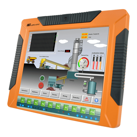
UPC-V312-D525 Panel PC
IEI Technology Corp.
MODEL:
UPC-V312-D525
Panel PC with Touch Screen and Intel® Atom™ CPU,
GbE, Wireless, GPS, RFID, USB, Audio,
RS-232/422/485, RoHS Compliant, IP 65 Protection
Rev. 1.02 – 23 August, 2012
UPC-V312-D525 Panel PC
User Manual
Page i
Advertisement

Related Manuals for IEI Technology 210UPC-V312


Summary of Contents for IEI Technology 210UPC-V312
- Page 1 UPC-V312-D525 Panel PC UPC-V312-D525 Panel PC IEI Technology Corp. MODEL: UPC-V312-D525 Panel PC with Touch Screen and Intel® Atom™ CPU, GbE, Wireless, GPS, RFID, USB, Audio, RS-232/422/485, RoHS Compliant, IP 65 Protection User Manual Page i Rev. 1.02 – 23 August, 2012...
- Page 2 UPC-V312-D525 Panel PC Revision Date Version Changes 23 August, 2012 1.02 Replaced IEI MiniDOM support with mSATA support 8 December, 2011 1.01 Updated Table 1-4: System Specifications Updated Section 2.2: Packing List Updated Section 3.5: Mounting the System 23 September, 2011 1.00 Initial release Page ii...
- Page 3 UPC-V312-D525 Panel PC Copyright COPYRIGHT NOTICE The information in this document is subject to change without prior notice in order to improve reliability, design and function and does not represent a commitment on the part of the manufacturer. In no event will the manufacturer be liable for direct, indirect, special, incidental, or consequential damages arising out of the use or inability to use the product or documentation, even if advised of the possibility of such damages.
- Page 4 UPC-V312-D525 Panel PC WARNING This device complies with Part 15 of the FCC Rules. Operation is subject to the following two conditions: (1) this device may not cause harmful interference, and(2) this device must accept any interference received, including interference that may cause undesired operation. NOTE: This equipment has been tested and found to comply with the limits for a Class B digital device, pursuant to part 15 of the FCC Rules.
- Page 5 UPC-V312-D525 Panel PC Table of Contents 1 INTRODUCTION......................1 1.1 O ........................2 VERVIEW 1.2 S ....................3 YSTEM ARIATIONS 1.3 F ........................3 EATURES 1.4 E ....................4 XTERNAL VERVIEW 1.4.1 Front Panel ......................4 1.4.1.1 LED Indicators.................... 5 1.4.2 Bottom Panel......................
- Page 6 UPC-V312-D525 Panel PC 3.6.2 ACC Mode Selection ..................32 3.6.3 AT/ATX Power Mode Selection................ 32 3.6.4 Audio Connectors..................... 33 3.6.5 CAN-bus Terminal Block.................. 33 3.6.6 LAN Connector ....................33 3.6.7 Power Input 1, 3-pin Terminal Block............... 35 3.6.8 Power Input 2, DIN Connector................ 35 3.6.9 RJ-45 RS-232 Serial Port.................
- Page 7 UPC-V312-D525 Panel PC 4.3.5.1 Serial Port n Configuration ............... 59 4.3.6 H/W Monitor ....................64 4.3.7 Serial Port Console Redirection ..............65 4.3.7.1 Console Redirection Settings..............66 4.3.8 IEI Feature ....................... 68 4.4 C ........................68 HIPSET 4.4.1 Host Bridge Configuration ................69 4.4.2 South Bridge Configuration................
- Page 8 UPC-V312-D525 Panel PC B.2.5 Create Factory Default Image............... 120 B.3 A ..............125 ECOVERY ETUP ROCEDURE B.4 S ................129 ETUP ROCEDURE FOR INUX B.5 R ................133 ECOVERY UNCTIONS B.5.1 Factory Restore ..................... 134 B.5.2 Backup System ....................135 B.5.3 Restore Your Last Backup................
- Page 9 UPC-V312-D525 Panel PC List of Figures Figure 1-1: UPC-V312-D525 Panel PC...................2 Figure 1-2: Front View ........................5 Figure 1-3: LED Indicators......................5 Figure 1-4: Bottom View ........................8 Figure 1-5: Left Side View......................8 Figure 1-6: Left Side View......................9 Figure 1-7: Rear View ........................9 Figure 1-8: Function Key Locations ...................10 Figure 1-9: UPC-V312-D525 Dimensions (mm)................11 Figure 3-1: Remove the CF Card Slot Panel ................22...
- Page 10 UPC-V312-D525 Panel PC Figure 3-27: RJ-45 RS-232 Serial Device Connection...............36 Figure 3-28: RS-422/485 Serial Port ....................37 Figure 3-29: RS-422/485 Cable ....................37 Figure 3-30: RS-422/485 Serial Port (DB-9) ................38 Figure 3-31: USB Device Connection ..................39 Figure 3-32: VGA Connector .......................40 Figure 3-33: VGA Connector .......................41 Figure 3-34: Power Connectors ....................42 Figure 3-35: ACC On: AT Mode ....................43 Figure 3-36: ACC On: ATX Mode....................43...
- Page 11 UPC-V312-D525 Panel PC Figure 5-19: Audio Driver Installation..................91 Figure 5-20: AC’97 Driver Installation Complete ...............91 Figure 5-21: Touch Screen Driver Welcome Screen ..............92 Figure 5-22: Touch Screen Driver License Agreement.............93 Figure 5-23: Touch Screen Driver Choose Install Location .............93 Figure 5-24: Touch Screen Driver Installation Screen..............94 Figure 5-25: Touch Screen Driver Update Complete ..............94 Figure 5-26: PenMount Monitor Icon ..................95 Figure 5-27: PenMount Monitor Popup Menu................95...
- Page 12 UPC-V312-D525 Panel PC Figure B-15: Select a Source Partition from Basic Drive ............122 Figure B-16: File Name to Copy Image to ................123 Figure B-17: Compress Image....................123 Figure B-18: Image Creation Confirmation ................124 Figure B-19: Image Creation Complete ................... 124 Figure B-20: Image Creation Complete ...................
- Page 13 UPC-V312-D525 Panel PC List of Tables Table 1-1: System Variations......................3 Table 1-2: LED Indicators ......................6 Table 1-3: Function Keys ......................10 Table 1-4: System Specifications....................14 Table 3-1: LAN Pinouts ........................33 Table 3-2: RJ-45 Ethernet Connector LEDs ................34 Table 3-3: RJ-45 RS-232 Serial Port Pinouts ................36 Table 3-4: RS-422/485 Serial Port Pinouts .................37 Table 3-5: RS-422/485 Serial Port Pinouts .................38 Table 3-6: USB Port Pinouts......................39...
- Page 15 UPC-V312-D525 Panel PC Chapter Introduction Page 1...
- Page 16 UPC-V312-D525 Panel PC 1.1 Overview Figure 1-1: UPC-V312-D525 Panel PC The fanless UPC-V312-D525 is Intel® Atom™ D525 powered panel PC with a rich variety of functions and peripherals. The UPC-V312-D525 panel PC is designed for easy and simplified integration into various vehicle applications. An Intel®...
- Page 17 UPC-V312-D525 Panel PC 1.2 System Variations The part numbers and system variations are listed below. Part Numbers RFID Reader Intel® Atom™ D525 UPC-V312-D525/R/1G-R10 UPC-V312-D525/R-EM/1G-R10 Intel® Atom™ D525 EM card reader UPC-V312-D525/R-MF/1G-R10 Intel® Atom™ D525 Mifare card reader Table 1-1: System Variations 1.3 Features The UPC-V312-D525 series features the following: 12.1'' 600nits 1024 x 768 LCD with LED backlight...
- Page 18 UPC-V312-D525 Panel PC 1.4 External Overview The panel PC is a rectangular cubic structure that comprises of a screen, rear panel, top panel, bottom panel and two side panels (left and right). An aluminum frame surrounds the front screen. The rear panel provides screw holes for a wall-mounting bracket, and an arm mounting interface.
- Page 19 UPC-V312-D525 Panel PC Figure 1-2: Front View 1.4.1.1 LED Indicators The LED indicators on the front panel of the UPC-V312-D525 are shown below. Figure 1-3: LED Indicators The descriptions of each LED indicator are listed below. LED Indicator Description Power 1 Pulsing Orange: Power 1 is the main power and is in standby mode Solid Orange: Power 1 is the second power and is in standby mode Page 5...
- Page 20 UPC-V312-D525 Panel PC Solid Blue: Power 1 is providing power to the system Power 2 Pulsing Orange: Power 2 is the main power and is in standby mode Solid Orange: Power 2 is the second power and is in standby mode Solid Blue: Power 2 is providing power to the system AT/ATX Power Mode Shows the power mode status.
- Page 21 UPC-V312-D525 Panel PC CAUTION: If the CPU temperature alert LED shows in red, the user must lower the environment temperature or close some running applications to cool down the CPU. 1.4.2 Bottom Panel The following is a list of the bottom panel peripheral device connectors on the UPC-V312-D525.
- Page 22 UPC-V312-D525 Panel PC Figure 1-4: Bottom View 1.4.3 Left Side Panel The left side panel of the panel PC provides access to the CF card slot. ( F igure 1-5). Figure 1-5: Left Side View Page 8...
Need help?
Do you have a question about the 210UPC-V312 and is the answer not in the manual?
Questions and answers