Table of Contents
Advertisement
Quick Links
Advertisement
Chapters
Table of Contents

Related Manuals for IEI Technology AFL3-12C-ULT3


Summary of Contents for IEI Technology AFL3-12C-ULT3
- Page 1 AFL3-12C-ULT3 Panel PC MODEL: AFL3-12C-ULT3 Flat Bezel Panel PC with Intel® Core™ i5-6300U / Celeron® 3855U CPU, Touchscreen, Four USB Ports, Dual GbE LAN, RS-232/422/485, HDMI, Wi-Fi 802.11a/b/g/n/ac and RoHS User Manual User Manual Page I Rev. 1.00 - May 7, 2018...
- Page 2 AFL3-12C-ULT3 Panel PC Revision Date Version Changes May 7, 2018 1.00 Initial release Page II...
- Page 3 AFL3-12C-ULT3 Panel PC Safety Instructions Warning! Read the user manual before connecting the system to the power source. Vorsicht! Bitte lesen Sie die Bedienungsanleitung, bevor Sie das System an eine Stromquelle anschließen. Attention! Avant de brancher le système à la source d'alimentation, consultez le mode d'emploi.
- Page 4 AFL3-12C-ULT3 Panel PC Warning! Use only the adapter and power cord approved for this system. Use of another type of adapter may risk fire or explosion. Please refer to the user manual for the power adapter specifications. Vorsicht! Nur zugelassene Netzteile und Netzkabel dürfen verwendet werden. Die Benutzung von anderen Netzteilen kann einen Brand oder eine Explosion zur Folge haben.
- Page 5 AFL3-12C-ULT3 Panel PC Copyright COPYRIGHT NOTICE The information in this document is subject to change without prior notice in order to improve reliability, design and function and does not represent a commitment on the part of the manufacturer. In no event will the manufacturer be liable for direct, indirect, special, incidental, or consequential damages arising out of the use or inability to use the product or documentation, even if advised of the possibility of such damages.
- Page 6 AFL3-12C-ULT3 Panel PC Manual Conventions WARNING Warnings appear where overlooked details may cause damage to the equipment or result in personal injury. Warnings should be taken seriously. CAUTION Cautionary messages should be heeded to help reduce the chance of losing data or damaging the product.
-
Page 7: Table Of Contents
AFL3-12C-ULT3 Panel PC Table of Contents 1 INTRODUCTION ......................1 1.1 O ........................2 VERVIEW 1.2 M ....................3 ODEL ARIATIONS 1.3 F ........................3 EATURES 1.4 F ......................4 RONT ANEL 1.5 B ......................5 OTTOM ANEL 1.6 R ....................... - Page 8 AFL3-12C-ULT3 Panel PC 3.9.1 Wall Mounting ....................26 3.9.2 Panel Mounting ....................30 3.9.3 Cabinet and Rack Installation ................. 33 3.9.4 Arm Mounting ....................36 3.9.5 Stand Mounting ....................38 3.10 P ................... 39 OWERING N THE YSTEM 3.11 R ....................
- Page 9 AFL3-12C-ULT3 Panel PC 4.4.1 System Agent (SA) Configuration ..............67 4.4.1.1 Graphics Configuration ................68 4.4.1.1.1 LCD Control ..................69 4.4.1.2 Memory Configuration ................70 4.4.2 PCH-IO Configuration ..................71 4.4.2.1 PCI Express Configuration ............... 72 4.4.2.2 HD Audio Configuration ................73 4.5 S...
- Page 10 AFL3-12C-ULT3 Panel PC 6.2.11 USB Connector (RFID_USB1)............... 93 6.2.12 USB Connector (TOUCH_USB1) ..............94 6.2.13 USB Power Connector (USB_HUB_P1) ............94 6.2.1 U72 Firmware Programming Connector (JP1) ..........94 6.2.1 Debug Connector (DBG_PORT1) ..............95 6.2.1 Debug Connector, EC (LPT_DB1) ..............95 6.2.1 SPI Flash Connector (JSPI1) ................
- Page 11 AFL3-12C-ULT3 Panel PC List of Figures Figure 1-1: AFL3-12C-ULT3 Flat Bezel Panel PC ................. 2 Figure 1-2: Front View ........................4 Figure 1-3: Bottom Panel ....................... 5 Figure 1-4: Rear View ........................5 Figure 1-5: Side View........................6 Figure 1-6: Dimensions (mm) ......................9 Figure 3-1: Back Cover Retention Screws .................
- Page 12 AFL3-12C-ULT3 Panel PC Figure 3-26: IEI Resource Download Center ................41 Figure 5-1: SO-DIMM module Location ..................82 Figure 5-2: SO-DIMM Installation ....................82 Figure 6-1: Main Board Layout Diagram ..................85 Page XII...
- Page 13 AFL3-12C-ULT3 Panel PC List of Tables Table 1-1: Model Variations ......................3 Table 1-2: System Specifications ....................8 Table 3-1: RS-232 Serial Port (COM1) Pinouts ................24 Table 3-2: RS-232/422/485 Serial Port (COM2) Pinouts ............25 Table 6-1: Peripheral Interface Connectors ................87 Table 6-2: Audio Connector (AUDIO_OUT1) Pinouts ..............
- Page 14 AFL3-12C-ULT3 Panel PC Table 6-28: HDMI Connector (HDMI1) Pinouts ................98 Table 6-29: Power Connector (PWR1) Pinouts ................98 Table 6-30: RS-232 RJ-45 Serial Port (COM1) Pinouts .............. 98 Table 6-31: RS-232/422/485 DB-9 Serial Port (COM2) Pinouts ..........99 Table 6-32: USB 3.0 Connectors (USB_CON12) Pinouts ............99 Table 6-33: USB 2.0 Connectors (USB2_CON1) Pinouts ............100...
- Page 15 AFL3-12C-ULT3 Panel PC List of BIOS Menus BIOS Menu 1: Main ........................48 BIOS Menu 2: Advanced ......................49 BIOS Menu 3: ACPI Settings ....................... 50 BIOS Menu 4: Super IO Configuration ..................51 BIOS Menu 5: Serial Port n Configuration ................. 51 BIOS Menu 6: Hardware Monitor ....................
-
Page 17: Introduction
AFL3-12C-ULT3 Panel PC Chapter Introduction Page 1... -
Page 18: Overview
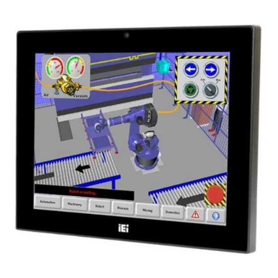
AFL3-12C-ULT3 Panel PC 1.1 Overview Figure 1-1: AFL3-12C-ULT3 Flat Bezel Panel PC ® ® ® The AFL3-12C-ULT3 series is a quad-core Intel Core™ i5-6300U or Intel Celeron 3855U powered flat bezel touchscreen panel PC with a rich variety of functions and peripherals. -
Page 19: Model Variations
AFL3-12C-ULT3 Panel PC 1.2 Model Variations There are several models in the AFL3-12C-ULT3 series. The model numbers and model variations are listed below. Model Processor ® ® AFL3-12C-ULT3-C/PC/4G Intel Celeron 3855U (2M cache, 1.60 GHz) ® AFL3-12C-ULT3-i5/PC/4G Intel Core™ i5-6300U (3M cache, up to 3.00 GHz) Table 1-1: Model Variations 1.3 Features... -
Page 20: Front Panel
AFL3-12C-ULT3 Panel PC 1.4 Front Panel The front side of the AFL3-12C-ULT3 is a flat-bezel panel with a TFT LCD screen surrounded by a PC/ABS plastic frame (Figure 1-2). Figure 1-2: Front View There is a power LED indicator located on the front panel. The status descriptions of the power LED indicator are listed below. -
Page 21: Bottom Panel
AFL3-12C-ULT3 Panel PC 1.5 Bottom Panel The bottom panel of the AFL3-12C-ULT3 has the following connectors and switches. Figure 1-3: Bottom Panel 1.6 Rear Panel The rear panel has two speakers and retention screw holes that support VESA mounting. The rear panel also has several retention screw holes for installing the optional barcode scanner and magnetic stripe card reader. -
Page 22: Side Panel
The right side panel has one E-Window that supports a variety of IEI modules to provide additional connector interface. Figure 1-5: Side View 1.8 System Specifications The technical specifications for the AFL3-12C-ULT3 systems are listed in Table 1-2. Specification AFL3-12C-ULT3 LCD Size 12.1"... - Page 23 AFL3-12C-ULT3 Panel PC ® ® ® CPU (SoC) Intel Core™ i5-6300U or Intel Celeron 3855U Memory One 260-pin 2133 MHz single-channel DDR4 SO-DIMM slot preinstalled with 4 GB SDRAM (system max. 8 GB) ® Ethernet Two Intel I211 PCIe GbE controllers...
-
Page 24: Table 1-2: System Specifications
AFL3-12C-ULT3 Panel PC Operating Temperature -20ºC ~ 50ºC (with air flow) Storage Temperature -20ºC ~ 60ºC Humidity 10% ~ 95% (non-condensing) Power Supply 96 W power adapter Input: 100 V ~ 240 V AC, 50 Hz ~ 60 Hz Output: 12 V DC, 8 A... -
Page 25: Dimensions
AFL3-12C-ULT3 Panel PC 1.9 Dimensions The following sections list the dimensions of the AFL3-12C-ULT3. Figure 1-6: Dimensions (mm) Page 9... -
Page 26: Unpacking
AFL3-12C-ULT3 Panel PC Chapter Unpacking Page 10... -
Page 27: Unpacking
If any of the components listed in the checklist below are missing, do not proceed with the installation. Contact the IEI reseller or vendor the AFL3-12C-ULT3 was purchased from or contact an IEI sales representative directly by sending an email to sales@ieiworld.com. - Page 28 AFL3-12C-ULT3 Panel PC The AFL3-12C-ULT3 flat bezel panel PC is shipped with the following components: Quantity Item Image AFL3-12C-ULT3 panel PC 96 W power adapter Power cord RJ-45 to DB-9 COM port cable Screws (M4*6) for VESA mounting Screws (M3*4) for HDD installation...
-
Page 29: Optional Items
AFL3-12C-ULT3 Panel PC 2.3 Optional Items The following are optional components which may be separately purchased: Item and Part Number Image VESA 100 wall mount kit (P/N: AFLWK-19B) Panel mounting kit (P/N: AFL3PK-08A-R10) Rack mounting kit (P/N: AFL3RK-12A-R10) (P/N: ARM-11-RS) - Page 30 AFL3-12C-ULT3 Panel PC Item and Part Number Image Stand for VESA 100 (P/N: STAND-A12-RS) Stand for VESA 75/VESA 100 (P/N: STAND-C12-R10) LCD monitor stand with adjustable hinge (P/N: VSTAND-A12) Magnetic card reader (P/N: AFL3P-W10MSR-U-R10) Barcode scanner (P/N: AFL3-2D-R11) If any of these items are missing or damaged, contact the distributor or sales representative immediately.
-
Page 31: Installation
AFL3-12C-ULT3 Panel PC Chapter Installation Page 15... -
Page 32: Anti-Static Precautions
AFL3-12C-ULT3 and severe injury to the user. Electrostatic discharge (ESD) can cause serious damage to electronic components, including the AFL3-12C-ULT3. Dry climates are especially susceptible to ESD. It is therefore critical that whenever the AFL3-12C-ULT3 is accessed internally, or any other electrical component is handled, the following anti-static precautions are strictly adhered ... -
Page 33: Installation And Configuration Steps
Mount the flat bezel panel PC. Step 0: 3.4 Removing the Back Covers To access the AFL3-12C-ULT3 internally the plastic back cover and the internal aluminum cover must be removed. To remove the covers, please follow the steps below. Step 1: Remove 12 retention screws from the back cover. -
Page 34: Msata Module Installation
See Figure 3-2 for detail. Figure 3-2: Aluminum Cover Retention Screws Step 4: Lift the aluminum cover off the AFL3-12C-ULT3. A thermal pad is attached under the center of the aluminum cover. Thus, more strength is required when lifting the aluminum cover. -
Page 35: Figure 3-3: Msata Module Slot Location
AFL3-12C-ULT3 Panel PC Figure 3-3: mSATA Module Slot Location Step 3: Remove the retention screw as shown in Figure 3-4. Figure 3-4: Removing the Retention Screw and Standoff Page 19... -
Page 36: Figure 3-5: Installing An Msata Module
AFL3-12C-ULT3 Panel PC Step 4: Line up the notch on the mSATA module with the notch on the connector. Slide the PCIe Mini card into the socket at an angle of about 20º (Figure 3-5). Figure 3-5: Installing an mSATA Module Step 5: Secure the mSATA module with the retention screw. -
Page 37: Hdd Installation
AFL3-12C-ULT3 Panel PC Step 6: Re-install the aluminum cover and the plastic back cover. Step 0: NOTE: To install a half-size mSATA module, remove both the retention screw and standoff of the PCIe Mini card slot, and install the standoff into the screw hole for the half-size card. -
Page 38: Figure 3-8: Hdd Retention Screws
(Figure 3-8). Figure 3-8: HDD Retention Screws Step 4: Install the HDD into the AFL3-12C-ULT3 by aligning the retention screw holes in the HDD brackets with the retention screw holes on the chassis. Insert the four retention screws. Step 5: Connect the SATA cable to the rear of HDD from the motherboard. -
Page 39: Serial Port Configuration And Connection
The RS-232 port (COM1) is a RJ-45 serial device connector on the bottom panel. The COM1 port connects to a cable with a standard D-sub 9 connector at the other end (cable included). Follow the steps below to connect a serial device to the AFL3-12C-ULT3 panel Step 1: Locate the RJ-45 connector. -
Page 40: Serial Port Pinouts
Table 3-1: RS-232 Serial Port (COM1) Pinouts 3.7.2 RS-232/422/485 Serial Port Connection The bottom panel of the AFL3-12C-ULT3 has one D-sub 9 male connector (COM2) for RS-232/422/485 connection. The serial communication mode selection can be made through the BIOS options. Please refer to Section 4.3.2.1.2 for detail information. The pinouts of the D-sub 9 connector are listed below. -
Page 41: At/Atx Mode Selection
Table 3-2: RS-232/422/485 Serial Port (COM2) Pinouts 3.8 AT/ATX Mode Selection AT or ATX power mode can be used on the AFL3-12C-ULT3. The selection is made through an AT/ATX switch located on the bottom panel (Figure 3-11). Figure 3-11: AT/ATX Switch Location 3.8.1 AT Power Mode... -
Page 42: Atx Power Mode
Manufacturing shop flow 3.8.2 ATX Power Mode With the ATX mode selected, the AFL3-12C-ULT3 panel PC goes in a standby mode when it is turned off. The panel PC can be easily turned on via network or a power switch in standby mode. -
Page 43: Figure 3-12: Wall-Mounting Bracket
AFL3-12C-ULT3 Panel PC Step 5: Secure the mounting-bracket to the wall by inserting the retention screws into the four pilot holes and tightening them (Figure 3-12). Figure 3-12: Wall-mounting Bracket Step 6: Insert the four monitor mounting screws provided in the wall mount kit into the four screw holes on the real panel of the flat bezel panel PC and tighten until the screw shank is secured against the rear panel (Figure 3-13). - Page 44 AFL3-12C-ULT3 Panel PC WARNING: Please use the M4 screws provided in the wall mount kit for the rear panel. If the screw is missing, the thread depth of the replacement screw should be not more than 4 mm. Step 7: Align the mounting screws on the monitor rear panel with the mounting holes on the bracket.
-
Page 45: Figure 3-13: Chassis Support Screws
AFL3-12C-ULT3 Panel PC Figure 3-13: Chassis Support Screws Step 9: Secure the panel PC by fastening the retention screw of the wall-mounting bracket (Figure 3-14). Figure 3-14: Secure the Panel PC Page 29... -
Page 46: Panel Mounting
AFL3-12C-ULT3 Panel PC 3.9.2 Panel Mounting To mount the AFL3-12C-ULT3 flat bezel panel PC into a panel, please follow the steps below. Step 1: Select the position on the panel to mount the panel PC. Step 2: Cut out a section corresponding to the size shown below. The size must be smaller than the outer edge. -
Page 47: Figure 3-16: Panel Mounting Kit Installation
AFL3-12C-ULT3 Panel PC Step 5: Repeat Step 4 to install the other three screws into the sides of the two panel mounting brackets. Figure 3-16: Panel Mounting Kit Installation Step 6: Align the panel mounting bracket screw holes with the VESA mounting holes on the rear of the panel PC. -
Page 48: Figure 3-17: Securing Panel Mounting Brackets
AFL3-12C-ULT3 Panel PC Figure 3-17: Securing Panel Mounting Brackets NOTE: The panel mounting kit described in this section is an optional item. To purchase it, please contact an IEI sales representative. Page 32... -
Page 49: Cabinet And Rack Installation
AFL3-12C-ULT3 Panel PC 3.9.3 Cabinet and Rack Installation The AFL3-12C-ULT3 flat bezel panel PC can be installed into a cabinet or rack. The installation procedures are similar to the panel mounting installation. To do this, please follow the steps below:... -
Page 50: Figure 3-18: Rack Mounting Kit Installation
AFL3-12C-ULT3 Panel PC Figure 3-18: Rack Mounting Kit Installation Step 4: Align the rack mounting bracket screw holes with the VESA mounting holes on the rear of the panel PC. Step 5: Secure the two rack mounting brackets to the rear of the panel PC by inserting the four retention screws into the VESA mounting holes and tightening them (Figure 3-19). -
Page 51: Figure 3-19: Securing Rack Mounting Brackets
AFL3-12C-ULT3 Panel PC Figure 3-19: Securing Rack Mounting Brackets Step 6: Slide the panel PC with the attached rack/cabinet bracket into a rack or cabinet (Figure 3-20). Figure 3-20: Install into a Rack/Cabinet Page 35... -
Page 52: Arm Mounting
When purchasing the arm please ensure that it is VESA compliant and that the arm has a 75 mm or a 100 mm interface pad. If the mounting arm is not VESA compliant it cannot be used to support the AFL3-12C-ULT3 flat bezel panel PC. -
Page 53: Figure 3-21: Arm Mounting Retention Screw Holes
AFL3-12C-ULT3 Panel PC Figure 3-21: Arm Mounting Retention Screw Holes Step 4: Secure the AFL3-12C-ULT3 to the interface pad by inserting four retention screws through the mounting arm interface pad and into the AFL3-12C-ULT3.S t e p 0 : Figure 3-22: Arm Mounting... -
Page 54: Stand Mounting
To mount the AFL3-12C-ULT3 using the stand mounting kit, please follow the steps below. Step 1: Locate the screw holes on the rear of the AFL3-12C-ULT3. This is where the bracket will be attached. Step 2: Align the bracket with the screw holes. -
Page 55: Powering On The System
Connect the power cord to the power adapter. Connect the other end of the power cord to a power source. Step 2: Connect the power adapter to the power connector of the AFL3-12C-ULT3. Step 3: Locate the power button on the I/O panel. -
Page 56: Reset The System
AFL3-12C-ULT3 Panel PC WARNING! Ensure to connect the power cord to a socket-outlet with earthing connection. 3.11 Reset the System The reset button enables user to reboot the system when the system is turned on. The reset button location is shown in Figure 3-25. Press the reset button to reboot the system. -
Page 57: Software Installation
AFL3-12C-ULT3 Panel PC 3.12 Software Installation All the drivers for the AFL3-12C-ULT3 are available on IEI Resource Download Center (https://download.ieiworld.com). Type AFL3-12C-ULT3 and press Enter to find all the relevant software, utilities, and documentation. Figure 3-26: IEI Resource Download Center IEI provides the following drivers for Windows 7, Windows 8 and Windows 10 operating systems. -
Page 58: Driver Download
AFL3-12C-ULT3 Panel PC 3.13 Driver Download To download drivers from IEI Resource Download Center, follow the steps below. Step 1: Go to https://download.ieiworld.com. Type AFL3-12C-ULT3AFL3-12C-ULT3AFL3-12C-ULT3 and press Enter. Step 2: All product-related software, utilities, and documentation will be listed. You can choose Driver to filter the result. -
Page 59: Installing Windows 7 From Usb 3.0 Drives
The Windows 7 USB 3.0 Creator Utility automates the steps to update a Windows 7 installation image so that it contains USB 3.0 drivers. To install Windows 7 from a USB drive onto the AFL3-12C-ULT3, please follow the steps described below. Step 1: Create a USB flash drive installer. - Page 60 AFL3-12C-ULT3 Panel PC Step 2: Download and unzip the Windows 7 USB 3.0 Creator utility to a temporary folder on the Admin system. Step 3: Connect the USB device containing the Windows 7 image to the Admin system. Step 4: Right-click the file “Installer_Creator.exe”...
-
Page 61: Bios Setup
AFL3-12C-ULT3 Panel PC Chapter BIOS Setup Page 45... -
Page 62: Introduction
AFL3-12C-ULT3 Panel PC 4.1 Introduction The BIOS is programmed onto the BIOS chip. The BIOS setup program allows changes to certain system settings. This chapter outlines the options that can be changed. NOTE: Some of the BIOS options may vary throughout the life cycle of the product and are subject to change without prior notice. -
Page 63: Getting Help
AFL3-12C-ULT3 Panel PC Function Decrease the numeric value or make changes F1 key General help, only for Status Page Setup Menu and Option Page Setup Menu F2 key Load previous values. F3 key Load optimized defaults F4 key Save changes and Exit BIOS Esc key Main Menu –... -
Page 64: Main
AFL3-12C-ULT3 Panel PC 4.2 Main The Main BIOS menu (BIOS Menu 1) appears when the BIOS Setup program is entered. Aptio Setup Utility – Copyright (C) 2018 American Megatrends, Inc. Main Advanced Chipset Security Boot Save & Exit BIOS Information... -
Page 65: Advanced
AFL3-12C-ULT3 Panel PC The System Overview field also has two user configurable fields: System Date [xx/xx/xx] Use the System Date option to set the system date. Manually enter the day, month and year. System Time [xx:xx:xx] Use the System Time option to set the system time. Manually enter the hours, minutes and seconds. -
Page 66: Acpi Settings
AFL3-12C-ULT3 Panel PC 4.3.1 ACPI Settings The ACPI Settings menu (BIOS Menu 3) configures the Advanced Configuration and Power Interface (ACPI) options. Aptio Setup Utility – Copyright (C) 2018 American Megatrends, Inc. Advanced ACPI Settings Select the highest ACPI sleep state the system... -
Page 67: Super Io Configuration
AFL3-12C-ULT3 Panel PC 4.3.2 Super IO Configuration Use the Super IO Configuration menu (BIOS Menu 4) to set or change the configurations for the serial ports. Aptio Setup Utility – Copyright (C) 2018 American Megatrends, Inc. Advanced F81866 Super IO Configuration... -
Page 68: Serial Port 1 Configuration
AFL3-12C-ULT3 Panel PC 4.3.2.1.1 Serial Port 1 Configuration Serial Port [Enabled] Use the Serial Port option to enable or disable the serial port. Disabled Disable the serial port Enable the serial port Enabled EFAULT Change Settings [Auto] Use the Change Settings option to change the serial port IO port address and interrupt address. -
Page 69: Serial Port 2 Configuration
AFL3-12C-ULT3 Panel PC 4.3.2.1.2 Serial Port 2 Configuration Serial Port [Enabled] Use the Serial Port option to enable or disable the serial port. Disabled Disable the serial port Enable the serial port Enabled EFAULT Change Settings [Auto] Use the Change Settings option to change the serial port IO port address and interrupt address. -
Page 70: Hardware Monitor
AFL3-12C-ULT3 Panel PC Transfer Mode [RS232] Use the Transfer Mode option to select the Serial Port 3 signaling mode. Serial Port 3 signaling mode is RS-422 RS422 Serial Port 3 signaling mode is RS-232 RS232 EFAULT ... -
Page 71: Iwdd H/W Monitor
AFL3-12C-ULT3 Panel PC 4.3.2 iWDD H/W Monitor The iWDD H/W Monitor menu (BIOS Menu 7) displays CPU temperature and system voltages. Aptio Setup Utility – Copyright (C) 2018 American Megatrends, Inc. Advanced PC Health Status CPU temperature :+34 °C CPU_CORE :+0.897 V... -
Page 72: Rtc Wake Settings
AFL3-12C-ULT3 Panel PC 4.3.3 RTC Wake Settings The RTC Wake Settings menu (BIOS Menu 8) configures RTC wake event. Aptio Setup Utility – Copyright (C) 2018 American Megatrends, Inc. Advanced Wake system with Fixed Time [Disabled] Enable or disable System wake on alarm event. -
Page 73: Serial Port Console Redirection
AFL3-12C-ULT3 Panel PC Wake up second After setting the alarm, the computer turns itself on from a suspend state when the alarm goes off. 4.3.4 Serial Port Console Redirection The Serial Port Console Redirection menu (BIOS Menu 9) allows the console redirection options to be configured. -
Page 74: Legacy Console Redirection Settings
AFL3-12C-ULT3 Panel PC 4.3.4.1 Legacy Console Redirection Settings The Legacy Console Redirection Settings menu (BIOS Menu 10) allows the legacy console redirection options to be configured. Aptio Setup Utility – Copyright (C) 2018 American Megatrends, Inc. Advanced Select a COM port to... -
Page 75: Console Redirection Settings
AFL3-12C-ULT3 Panel PC 4.3.4.2 Console Redirection Settings The Console Redirection Settings menu (BIOS Menu 11) allows the console redirection options to be configured. The option is active when Console Redirection option is enabled. Aptio Setup Utility – Copyright (C) 2018 American Megatrends, Inc. -
Page 76: Bits Per Second [115200]
AFL3-12C-ULT3 Panel PC Bits per second [115200] Use the Bits per second option to specify the serial port transmission speed. The speed must match the other side. Long or noisy lines may require lower speeds. 9600 Sets the serial port transmission speed at 9600. -
Page 77: Cpu Configuration
AFL3-12C-ULT3 Panel PC Stop Bits [1] Use the Stop Bits option to specify the number of stop bits used to indicate the end of a serial data packet. Communication with slow devices may require more than 1 stop bit. -
Page 78: Hyper Threading Function [Enabled]
AFL3-12C-ULT3 Panel PC Hyper Threading Function [Enabled] Use the Hyper Threading function to enable or disable the CPU hyper threading function. Disables the use of hyper threading technology Disabled Enables the use of hyper threading technology Enabled EFAULT ... -
Page 79: Sata Configuration
AFL3-12C-ULT3 Panel PC CPU C State [Disabled] Use the CPU C State option to enable or disable CPU C state. Disables CPU C state. Disabled EFAULT Enables CPU C state. Enabled 4.3.6 SATA Configuration Use the SATA Configuration menu (BIOS Menu 13) to change and/or set the configuration of the SATA devices installed in the system. -
Page 80: Sata Mode Selection [Ahci]
AFL3-12C-ULT3 Panel PC SATA Mode Selection [AHCI] Use the SATA Mode Selection option to configure SATA devices as AHCI devices. Configures SATA devices as AHCI device. AHCI EFAULT Configures SATA devices as RAID device. RAID NOTE: Before accessing the RAID configuration utility, ensure to set the Option ROM Messages BIOS option in the Boot menu to Force BIOS. -
Page 81: Usb Configuration
AFL3-12C-ULT3 Panel PC 4.3.7 USB Configuration Use the USB Configuration menu (BIOS Menu 14) to read USB configuration information and configure the USB settings. Aptio Setup Utility – Copyright (C) 2018 American Megatrends, Inc. Advanced USB Configuration Enables Legacy USB support. -
Page 82: Iei Feature
AFL3-12C-ULT3 Panel PC Enabled Legacy USB support enabled EFAULT Legacy USB support disabled Disabled Auto Legacy USB support disabled if no USB devices are connected 4.3.8 IEI Feature Use the IEI Feature menu (BIOS Menu 15) to configure One Key Recovery function. -
Page 83: Chipset
AFL3-12C-ULT3 Panel PC 4.4 Chipset Use the Chipset menu (BIOS Menu 16) to configure the system chipset. Aptio Setup Utility – Copyright (C) 2018 American Megatrends, Inc. Main Advanced Chipset Security Boot Save & Exit > System Agent (SA) Configuration System Agent (SA) >... -
Page 84: Graphics Configuration
AFL3-12C-ULT3 Panel PC VT-d [Disabled] Use the VT-d option to enable or disable VT-d support. Disable VT-d support. Disabled EFAULT Enable VT-d support. Enabled 4.4.1.1 Graphics Configuration Use the Graphics Configuration menu (BIOS Menu 18) to configure the graphics settings. -
Page 85: Lcd Control
AFL3-12C-ULT3 Panel PC 256M EFAULT 512M DVMT Total Gfx Mem [MAX] Use the DVMT Total Gfx Mem option to select DVMT 5.0 total graphic memory size used by the internal graphics device. The following options are available: ... -
Page 86: Memory Configuration
AFL3-12C-ULT3 Panel PC Primary IGFX Boot Display [VBIOS Default] Use the Primary IGFX Boot Display option to select the display device used by the system when it boots. VBIOS Default EFAULT HDMI1 LVDS 4.4.1.2 Memory Configuration Use the Memory Configuration submenu (BIOS Menu 20) to display the memory information. -
Page 87: Pch-Io Configuration
AFL3-12C-ULT3 Panel PC 4.4.2 PCH-IO Configuration Use the PCH-IO Configuration menu (BIOS Menu 21) to configure the PCH-IO chipset. Aptio Setup Utility – Copyright (C) 2018 American Megatrends, Inc. Chipset Auto Power Button Status [Disable (ATX)] Select AC power state when... -
Page 88: Pci Express Configuration
AFL3-12C-ULT3 Panel PC USB Power SW [+5V DUAL] Use the USB Power SW BIOS option to configure whether to provide power to the four external USB connectors when the system is in S3/S4 sleep state. This option is valid only when the above Power Saving Function (ERP) BIOS option is disabled. -
Page 89: Hd Audio Configuration
AFL3-12C-ULT3 Panel PC Gen 2 Gen 3 Detect Non-Compliance Device [Disabled] Use the Detect Non-Compliance Device option to enable or disable detecting if a non-compliance PCI Express device is connected to the PCI Express slot. Disabled... -
Page 90: Security
AFL3-12C-ULT3 Panel PC HD Audio [Enabled] Use the HD Audio BIOS option to enable or disable the High Definition Audio controller. The High Definition Audio controller is disabled. Disabled The High Definition Audio controller is enabled. Enabled EFAULT 4.5 Security... -
Page 91: Boot
AFL3-12C-ULT3 Panel PC 4.6 Boot Use the Boot menu (BIOS Menu 25) to configure system boot options. Aptio Setup Utility – Copyright (C) 2018 American Megatrends, Inc. Main Advanced Chipset Security Boot Save & Exit Boot Configuration Select the keyboard... -
Page 92: Quiet Boot [Enabled]
AFL3-12C-ULT3 Panel PC Quiet Boot [Enabled] Use the Quiet Boot BIOS option to select the screen display when the system boots. Normal POST messages displayed Disabled OEM Logo displayed instead of POST messages Enabled EFAULT UEFI Boot [Disabled] Use the UEFI Boot option to enable or disable to boot from the UEFI devices. -
Page 93: Save & Exit
AFL3-12C-ULT3 Panel PC 4.7 Save & Exit Use the Save & Exit menu (BIOS Menu 26) to load default BIOS values, optimal failsafe values and to save configuration changes. Aptio Setup Utility – Copyright (C) 2018 American Megatrends, Inc. Main... -
Page 94: Save As User Defaults
AFL3-12C-ULT3 Panel PC Save as User Defaults Use the Save as User Defaults option to save the changes done so far as user defaults. Restore User Defaults Use the Restore User Defaults option to restore the user defaults to all the setup options. -
Page 95: System Maintenance
AFL3-12C-ULT3 Panel PC Chapter System Maintenance Page 79... -
Page 96: System Maintenance Introduction
AFL3-12C-ULT3 Panel PC 5.1 System Maintenance Introduction If the components of the AFL3-12C-ULT3 fail they must be replaced. Please contact the system reseller or vendor to purchase the replacement parts. Back cover removal instructions for the AFL3-12C-ULT3 are described below. -
Page 97: Turn Off The Power
Before any maintenance procedures are carried out on the system, make sure the system is turned off. 5.4 SO-DIMM Module Replacement The AFL3-12C-ULT3 has one SO-DIMM module installed. To replace the SO-DIMM module, follow the instructions below. Step 1: Follow all anti-static procedures. See Section 5.2. -
Page 98: Figure 5-1: So-Dimm Module Location
AFL3-12C-ULT3 Panel PC Figure 5-1: SO-DIMM module Location Step 5: Remove the DDR4 memory module by pulling both the spring retainer clips outward from the socket. Step 6: Grasp the DDR4 memory module by the edges and carefully pull it out of the socket. - Page 99 AFL3-12C-ULT3 Panel PC Step 9: Reinstall the internal aluminum cover and the plastic back cover using the previously removed retention screws. Step 0: WARNING: Failing to reinstall the cover may result in permanent damage to the system. Please make sure all coverings are properly installed.
-
Page 100: Interface Connectors
AFL3-12C-ULT3 Panel PC Chapter Interface Connectors Page 84... -
Page 101: Peripheral Interface Connectors
AFL3-12C-ULT3 Panel PC 6.1 Peripheral Interface Connectors The connector locations of the motherboard are shown in Figure 6-1 and Figure 6-2. The Pin 1 locations of the on-board connectors are also indicated in the diagram below. The connector pinouts for these connectors are listed in the following sections. -
Page 102: Internal Peripheral Connectors
AFL3-12C-ULT3 Panel PC 6.2 Internal Peripheral Connectors Internal peripheral connectors are found on the motherboard and are only accessible when the motherboard is outside of the chassis. The table below shows a list of the peripheral interface connectors on the motherboard. Pinouts of these connectors can be found in the following sections. -
Page 103: Audio Connector (Audio_Out1)
AFL3-12C-ULT3 Panel PC Connector Type Label Front Side USB connectors 4-pin wafer HUB_USB1 CAM_USB1 RFID_USB1 TOUCH_USB1 USB power connector 2-pin wafer USB_HUB_P1 U72 firmware programming connector 9-pin wafer Solder Side Debug connector 12-pin wafer DBG_PORT1 Debug connector - EC 20-pin LPC... -
Page 104: Audio Out Connector (Audio_Out_R1)
AFL3-12C-ULT3 Panel PC 6.2.1 Audio Out Connector (AUDIO_OUT_R1) PIN NO. DESCRIPTION SPK_OUT_P_R SPK_OUT_N_R Table 6-4: Audio Out Connector (AUDIO_OUT_R1) Pinouts 6.2.2 Battery Connector (BAT1) PIN NO. DESCRIPTION VBATT Table 6-5: Battery Connector (BAT1) Pinouts CAUTION: – risk of explosion if the battery is replaced by an incorrect type;... -
Page 105: Digital I/O Connector (Dio1)
AFL3-12C-ULT3 Panel PC 6.2.3 Digital I/O Connector (DIO1) PIN NO. DESCRIPTION PIN NO. DESCRIPTION DOUT3 DOUT2 DOUT1 DOUT0 DIN3 DIN2 DIN1 DIN0 Table 6-6: Digital I/O Connector (DIO1) Pinouts 6.2.1 Fan Connector (CPU/FAN1) PIN NO. -
Page 106: Lvds Connector (Lvds1)
AFL3-12C-ULT3 Panel PC 6.2.3 LVDS Connector (LVDS1) PIN NO. DESCRIPTION PIN NO. DESCRIPTION BKL_POWER BKL_POWER A3P_L A3M_L CLK1P_L CLK1M_L A2P_L A2M_L A1P_L A1M_L A0P_L A0M_L VCC_LCD VCC_LCD Table 6-9: LVDS Connector (LVDS1) Pinouts 6.2.4 Microphone Connector (DMIC1) PIN NO. DESCRIPTION... -
Page 107: Pcie Mini Connector, Full-Size/Half-Size (M_Pcie1)
AFL3-12C-ULT3 Panel PC 6.2.5 PCIe Mini Connector, Full-Size/Half-size (M_PCIE1) PIN NO. DESCRIPTION PIN NO. DESCRIPTION PCIE_WAKE# VCC3 1.5V VCC3 CLK- CLK+ PCIRST# VCC3 PCIRST# PERN(SATA_RX1+) 3VDual PERP(SATA_RX1-) 1.5V SMBCLK PETN SMBDATA PETP USBD- USBD+ VCC3 VCC3 1.5V MSATA_SEL# VCC3 Table 6-11: PCIe Mini Connector (M_PCIE1) Pinouts... -
Page 108: Power Button Connector (Pwr_Btn1)
AFL3-12C-ULT3 Panel PC 6.2.6 Power Button Connector (PWR_BTN1) PIN NO. DESCRIPTION PWR_BTN+ Table 6-12: Power Button Connector (PWR_BTN1) Pinouts 6.2.7 Power LED Connector (PW_LED1) PIN NO. DESCRIPTION PW_LED +5V SUS PW LED +5V Table 6-13: Power LED Connector (PW_LED1) Pinouts 6.2.8 SATA Connector (SATA1) -
Page 109: Usb Connector (Hub_Usb1)
AFL3-12C-ULT3 Panel PC 6.2.9 USB Connector (HUB_USB1) PIN NO. DESCRIPTION USB_DATA- USB_DATA+ Table 6-15: USB Connector (HUB_USB1) Pinouts 6.2.10 USB Connector (CAM_USB1) PIN NO. DESCRIPTION USB_DATA- USB_DATA+ Table 6-16: USB Connector (CAM_USB1) Pinouts 6.2.11 USB Connector (RFID_USB1) PIN NO. DESCRIPTION... -
Page 110: Usb Connector (Touch_Usb1)
AFL3-12C-ULT3 Panel PC 6.2.12 USB Connector (TOUCH_USB1) PIN NO. DESCRIPTION USB_DATA- USB_DATA+ Table 6-18: USB Connector (TOUCH_USB1) Pinouts 6.2.13 USB Power Connector (USB_HUB_P1) PIN NO. DESCRIPTION +V5A Table 6-19: USB Power Connector (USB_USB_P1) Pinouts 6.2.1 U72 Firmware Programming Connector (JP1) PIN NO. -
Page 111: Debug Connector (Dbg_Port1)
AFL3-12C-ULT3 Panel PC 6.2.1 Debug Connector (DBG_PORT1) PIN NO. DESCRIPTION PIN NO. DESCRIPTION +V5S +V3.3S INT_SERIRQ LPC_AD3 LPC_AD2 LPC_AD1 LPC_AD0 FRAME# PLT_RST# PLT_CLK Table 6-21: Debug Connector (DBG_PORT1) Pinouts 6.2.1 Debug Connector, EC (LPT_DB1) PIN NO. DESCRIPTION PIN NO. DESCRIPTION... -
Page 112: Spi Flash Connector, Ec (Jspi2)
AFL3-12C-ULT3 Panel PC SPI_CLK_N SPI_SI_N Table 6-23: SPI Flash Connector (JSPI1) Pinouts 6.2.1 SPI Flash Connector, EC (JSPI2) PIN NO. DESCRIPTION +V3.3M_SPI_CON_EC SPI_CS#0_CN_EC SPI_SO_SW_EC SPI_CLK_SW_EC SPI_SI_SW_EC Table 6-24: EC SPI Flash Connector (JSPI2) Pinouts 6.2.2 Touch Panel Connector (TOUCH1) DESCRIPTION PIN NO. -
Page 113: External Interface Panel Connectors
AFL3-12C-ULT3 Panel PC 6.3 External Interface Panel Connectors The table below lists the rear panel connectors on the AFL3MB-ULT3 motherboard. Pinouts of these connectors can be found in the following sections. Connector Type Label Ethernet connectors RJ-45 LAN1, LAN2 HDMI connector... -
Page 114: Hdmi Connector (Hdmi1)
AFL3-12C-ULT3 Panel PC 6.3.2 HDMI Connector (HDMI1) PIN NO. DESCRIPTION PIN NO. DESCRIPTION HDMI_DATA2+ HDMI_CLK# HDMI_DATA2#- HDMI_DATA1+ HDMI_SCL HDMI_DATA1#- HDMI_SDA HDMI_DATA0+ +5VCC HDMI_DATA0#- HDMI_HPD HDMI_CLK+ Table 6-28: HDMI Connector (HDMI1) Pinouts 6.3.3 Power Connector (PWR1) Table 6-29: Power Connector (PWR1) Pinouts 6.3.1 RS-232 RJ-45 Serial Port (COM1) -
Page 115: Rs-232/422/485 Db-9 Serial Port (Com2)
AFL3-12C-ULT3 Panel PC 6.3.2 RS-232/422/485 DB-9 Serial Port (COM2) PIN NO. RS-232 RS-422 RS-485 TXD422- TXD485- TXD422+ TXD485+ SOUT RXD422+ RXD422- Table 6-31: RS-232/422/485 DB-9 Serial Port (COM2) Pinouts 6.3.3 USB 3.0 Connectors (USB3_CON1) PIN NO. DESCRIPTION PIN NO. DESCRIPTION... -
Page 116: Usb 2.0 Connectors (Usb2_Con1)
DATA1- DATA0+ DATA1+ Table 6-33: USB 2.0 Connectors (USB2_CON1) Pinouts 6.4 Preconfigured Jumper Settings CAUTION: The following jumpers are preconfigured for the AFL3-12C-ULT3. Users should not change these jumpers (Table 6-34). Jumper Name Type Label LVDS voltage selection 6-pin header... -
Page 117: Lvds Panel Voltage Selection Jumper (J_Vlvds1)
AFL3-12C-ULT3 Panel PC 6.4.1 LVDS Panel Voltage Selection Jumper (J_VLVDS1) Description Short 1-2 +3.3 V Short 3-4 +5 V (Default) Short 5-6 +12 V Table 6-35: LVDS Voltage Selection Jumper (J_VLVDS1) Settings 6.4.2 LVDS Panel Resolution Selection Jumper (SW1) * ON=0, OFF=1; Single=S, Dual=D... -
Page 118: Flash Descriptor Security Override Jumper
AFL3-12C-ULT3 Panel PC 6.4.3 Flash Descriptor Security Override Jumper The Flash Descriptor Security Override jumper (ME_FLASH1) allows to enable or disable the ME firmware update. Setting Description Open Disabled (default) Short Enabled Table 6-37: Flash Descriptor Security Override Jumper Settings To update the ME firmware, please follow the steps below. -
Page 119: A Regulatory Compliance
AFL3-12C-ULT3 Panel PC Appendix Regulatory Compliance Page 103... - Page 120 AFL3-12C-ULT3 Panel PC DECLARATION OF CONFORMITY This equipment is in conformity with the following EU directives: EMC Directive (2004/108/EC, 2014/30/EU) Low-Voltage Directive (2006/95/EC, 2014/35/EU) RoHS II Directive (2011/65/EU, 2015/863/EU) If the user modifies and/or install other devices in the equipment, the CE conformity declaration may no longer apply.
- Page 121 AFL3-12C-ULT3 Panel PC Español [Spanish] IEI Integration Corp declara que el equipo cumple con los requisitos esenciales y cualesquiera otras disposiciones aplicables o exigibles de la Directiva 2014/53/EU. Ελληνική [Greek] IEI Integration Corp ΔΗΛΩΝΕΙ ΟΤΙ ΕΞΟΠΛΙΣΜΟΣ ΣΥΜΜΟΡΦΩΝΕΤΑΙ ΠΡΟΣ ΤΙΣ ΟΥΣΙΩΔΕΙΣ ΑΠΑΙΤΗΣΕΙΣ ΚΑΙ ΤΙΣ ΛΟΙΠΕΣ ΣΧΕΤΙΚΕΣ ΔΙΑΤΑΞΕΙΣ ΤΗΣ ΟΔΗΓΙΑΣ...
- Page 122 AFL3-12C-ULT3 Panel PC Româna [Romanian] IEI Integration Corp declară că acest echipament este in conformitate cu cerinţele esenţiale şi cu celelalte prevederi relevante ale Directivei 2014/53/EU. Slovensko [Slovenian] IEI Integration Corp izjavlja, da je ta opreme v skladu z bistvenimi zahtevami in ostalimi relevantnimi določili direktive 2014/53/EU.
- Page 123 AFL3-12C-ULT3 Panel PC FCC WARNING This equipment complies with Part 15 of the FCC Rules. Operation is subject to the following two conditions: This device may not cause harmful interference, and This device must accept any interference received, including interference that may cause undesired operation.
- Page 124 AFL3-12C-ULT3 Panel PC CHINA ROHS The label on the product indicates the estimated “Environmentally Friendly Use Period” (EFUP). This is an estimate of the number of years that these substances would “not leak undergo abrupt change.” This product contain replaceable sub-assemblies/components which have a shorter EFUP such as batteries and lamps.
-
Page 125: B Safety Precautions
AFL3-12C-ULT3 Panel PC Appendix Safety Precautions Page 109... -
Page 126: Safety Precautions
Electric shocks can occur if the AFL3-12C-ULT3 chassis is opened when it is running. To avoid risk of electric shock, this device must only be connected to a supply mains with protective earth. -
Page 127: Anti-Static Precautions
Electrostatic discharge (ESD) can cause serious damage to electronic components, including the AFL3-12C-ULT3. Dry climates are especially susceptible to ESD. It is therefore critical that whenever the AFL3-12C-ULT3 is opened and any of the electrical components are handled, the following anti-static precautions are strictly adhered to. -
Page 128: Product Disposal
AFL3-12C-ULT3 Panel PC B.1.3 Product Disposal CAUTION: Risk of explosion if battery is replaced by an incorrect type. Only certified engineers should replace the on-board battery. Dispose of used batteries according to instructions and local regulations. Outside the European Union–If you wish to dispose of used electrical and electronic products outside the European Union, please contact your local authority so as to comply with the correct disposal method. -
Page 129: Maintenance And Cleaning Precautions
Some components in the AFL3-12C-ULT3 may only be cleaned using a product specifically designed for the purpose. In such case, the product will be explicitly mentioned in the cleaning tips. Below is a list of items to use when cleaning the AFL3-12C-ULT3. ... - Page 130 AFL3-12C-ULT3 Panel PC Water or rubbing alcohol–A cloth moistened with water or rubbing alcohol can be used to clean the device. Using solvents–The use of solvents is not recommended when cleaning the device as they may damage the plastic parts.
-
Page 131: Cbios Menu Options
AFL3-12C-ULT3 Panel PC Appendix BIOS Menu Options Page 115... - Page 132 AFL3-12C-ULT3 Panel PC System Date [xx/xx/xx] ......................49 System Time [xx:xx:xx] ....................... 49 ACPI Sleep State [S3 (Suspend to RAM)] ................50 Serial Port [Enabled] ......................52 Change Settings [Auto] ....................... 52 Serial Port [Enabled] ......................53 Change Settings [Auto] ....................... 53 Transfer Mode [RS232] ......................
- Page 133 AFL3-12C-ULT3 Panel PC Detect Non-Compliance Device [Disabled] ............... 73 HD Audio [Enabled] ......................74 Administrator Password ..................... 74 User Password ........................74 Bootup NumLock State [On] ....................75 Quiet Boot [Enabled] ......................76 UEFI Boot [Disabled] ......................76 Launch PXE OpROM [Disabled] ..................76 Option ROM Messages [Force BIOS] .................
-
Page 134: D Watchdog Timer
AFL3-12C-ULT3 Panel PC Appendix Watchdog Timer Page 118... - Page 135 AFL3-12C-ULT3 Panel PC NOTE: The following discussion applies to DOS. Contact IEI support or visit the IEI website for drivers for other operating systems. The Watchdog Timer is a hardware-based timer that attempts to restart the system when it stops working. The system may stop working because of external EMI or software bugs.
- Page 136 AFL3-12C-ULT3 Panel PC NOTE: The Watchdog Timer is activated through software. The software application that activates the Watchdog Timer must also deactivate it when closed. If the Watchdog Timer is not deactivated, the system will automatically restart after the Timer has finished its countdown.
-
Page 137: E Hazardous Materials Disclosure
AFL3-12C-ULT3 Panel PC Appendix Hazardous Materials Disclosure Page 121... - Page 138 AFL3-12C-ULT3 Panel PC The details provided in this appendix are to ensure that the product is compliant with the Peoples Republic of China (China) RoHS standards. The table below acknowledges the presences of small quantities of certain materials in the product, and is applicable to China RoHS only.
- Page 139 AFL3-12C-ULT3 Panel PC 此附件旨在确保本产品符合中国 RoHS 标准。以下表格标示此产品中某有毒物质的含量符 合中国 RoHS 标准规定的限量要求。 本产品上会附有”环境友好使用期限”的标签,此期限是估算这些物质”不会有泄漏或突变”的 年限。本产品可能包含有较短的环境友好使用期限的可替换元件,像是电池或灯管,这些元 件将会单独标示出来。 部件名称 有毒有害物质或元素 铅 汞 镉 六价铬 多溴联苯 多溴二苯 醚 (Pb) (Hg) (Cd) (CR(VI)) (PBB) (PBDE) 壳体 显示 印刷电路板 金属螺帽 电缆组装 风扇组装 电力供应组装 电池 O: 表示该有毒有害物质在该部件所有物质材料中的含量均在 SJ/T 11363-2006 (现由 GB/T 26572-2011 取代) 标准规定的限量要求以下。...
Need help?
Do you have a question about the AFL3-12C-ULT3 and is the answer not in the manual?
Questions and answers