Table of Contents

Related Manuals for Moxa Technologies ToughNet TN-4500A Series


Summary of Contents for Moxa Technologies ToughNet TN-4500A Series
- Page 1 TN-4500A Series (HW 1.x, 2.x) Quick Installation Guide Moxa ToughNet Switch Version 3.1, June 2023 Technical Support Contact Information www.moxa.com/support 2023 Moxa Inc. All rights reserved. P/N: 1802045000014 *1802045000014*...
-
Page 2: Package Checklist
Overview The ToughNet TN-4500A Series M12 managed Ethernet switches are designed for industrial applications in harsh environments. The TN series switches use M12 connectors to ensure tight, robust connections, and guarantee reliable operation against environmental disturbances, such as vibration and shock. The wide 24 to 110 VDC dual power inputs increases the reliability of your communications. - Page 3 Hardware Version Appearance The appearance of different TN-4500A Series hardware versions may not be similar. For example, the shape and positions of LEDs on the TN- 4516A hardware version 3.x are different from previous hardware versions. Secondly, the trenches on the front side are removed for hardware version 3.x.
-
Page 4: Recommended Optional Accessories
• 802.3ad, LACP for optimum bandwidth utilization • TACACS+, SNMPv3, IEEE 802.1X, HTTPS, and SSH to enhance network security • SNMP v1/v2c/v3 for different levels of network management • RMON for efficient network monitoring and proactive capability • Bandwidth management prevents unpredictable network status •... - Page 5 • M12X-8PMM-IP67-HTG: Field-installable M12 X-coded crimp type, slim design connector, 8-pin male, IP67-rated • A-CAP-M12F-M-PP: Metal cap for M12 female connector • A-CAP-M12M-M: Metal cap for M12 male connector • A-PLG-WPM23-01-IP67: M23 cable connector, 6-pin female, crimp type • ABC-01-M12: Configuration backup and restoration tool with M12 connector for managed Ethernet switches and wireless APs/Bridges/Clients, 0 to 60°C operating temperature ATTENTION...
- Page 6 • TN-4528A PoE models: Ports 1 to 16, ports G1 to G4 • TN-4528A 2GTXBP and ODC models: Ports 1 to 16, ports G3 and TN-4516A Non-PoE Models Panel Layouts 1. Model name 2. Screw holes for panel mounting kit 3.
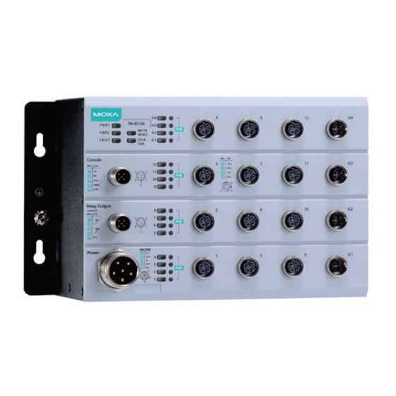
- Page 7 TN-4516A PoE Models Panel Layouts 1. Model name 2. Screw holes for panel mounting kit 3. Console port 4. Grounding screw 5. Relay output port 6. Power input voltage range indicator 7. Power input port (male 6-pin shielded M23 connector) 8.
- Page 8 TN-4516A Fiber Models Panel Layouts 1. Model name 2. Screw holes for panel mounting kit 3. Console port 4. Grounding screw 5. Relay output port 6. Power input voltage range indicator 7. Power input port (male 6-pin shielded M23 connector) 8.
- Page 9 TN-4524A PoE Models Panel Layouts 1. Model name 2. Screw holes for panel mounting kit 3. Console port 4. Grounding screw 5. Relay output port 6. Power input voltage range indicator 7. Power input port (male 6-pin shielded M23 connector) 8.
- Page 10 TN-4528A PoE Models Panel Layouts 1. Model name 2. Screw holes for panel mounting kit 3. Console port 4. Grounding screw 5. Relay output port 6. Power input voltage range indicator 7. Power input port (male 6-pin shielded M23 connector) 8.
- Page 11 TN-4528A Fiber Models Panel Layouts 1. Model name 2. Screw holes for panel mounting kit 3. Console port 4. Grounding screw 5. Relay output port 6. Power input voltage range indicator 7. Power input port (male 6-pin shielded M23 connector) 8.
-
Page 12: Mounting Dimensions (Unit = Mm)
ATTENTION Exposed connectors when not in use must be tightly covered with protective caps (an optional accessory) to ensure IP42- rated protection. Mounting Dimensions (unit = mm) TN-4516A Non-PoE Models - 12 -... - Page 13 TN-4516A PoE Models - 13 -...
- Page 14 TN-4516A Fiber Models - 14 -...
- Page 15 TN-4524A PoE Models TN-4528A PoE Models - 15 -...
-
Page 16: Panel/Wall Mounting
TN-4528A Fiber Models Panel/Wall Mounting STEP 1: Mounting the TN-4500A to a wall requires 4 screws. Use the ToughNet switch as a guide to mark the correct position of the 4 screws. STEP 2: Use the 4 screws in the panel mounting kit. -
Page 17: Wiring Requirements
NOTE To provide greater protection against vibration and shock, use screws with a shaft diameter between 6.0 mm and 7.0 mm, and fix the ToughNet switch onto the wall directly using the large opening of the keyhole-shaped apertures. NOTE The TN-4500A Series switches have passed IP42 certification. To achieve IP42 protection, only use upright panel or wall mounting installation. -
Page 18: Grounding The Toughnet Switch
ATTENTION Safety First! Be sure to disconnect the power cord before installing and/or wiring your Moxa switch. This device has UL 61010-2-201 approval. Use copper conductors only, 75°C, and tighten to 4.5 pound-inches. For use in pollution degree 2 environments. ATTENTION Safety First! Observe all electrical codes dictating the maximum current... -
Page 19: Connecting The Power Supplies
Connecting the Power Supplies The ToughNet TN-4500A Series switches support dual power inputs— power input 1 and power input 2. The M23 6-pin male connector on the TN-4500A Series switches' front panel is used for the dual power inputs. -
Page 20: Connecting The Relay Outputs
ATTENTION Do not power on the TN-4500A Series before connecting the M23 connector. Connecting the Relay Outputs Each TN-4500A Series switch has two sets of relay outputs—relay output 1 and relay output 2. The M12 A-coded 5-pin male connector on the TN-4500A Series’... - Page 21 Housing: shield Pinouts for the 10/100/1000BaseT(X) M12 (8-pin) Port PoE Pinout D-coded X-coded Pin 1, 3 (TD+, TD-) Pin 1, 2 (DA+, DA-) Pin 2, 4 (RD+, RD-) Pin 3, 4 (DB+, DB-) Pinouts for the 1000BaseLSX Q-ODC® Gigabit Fiber port Connecting Procedure Rotate to find the keying Push the connector to...
- Page 22 CAUTION Use of controls, adjustments, or the performance of procedures other than those specified herein may result in hazardous radiation exposure. - Complies with FDA performance standards for laser products except for conformance with IEC 60825-1 Ed. 3., as described in Laser Notice No.
- Page 23 M12 (4-pin, M) to RJ45 (8-pin) Straight-through Cable Wiring M12 (8-pin, M) to M12 (8-pin, M) Cross-over Cable Wiring M12 (8-pin, M) to M12 (8-pin, M) Straight-through Cable Wiring - 23 -...
- Page 24 M12 (8-pin, M) to RJ45 (8-pin) Cross-over Cable Wiring M12 (8-pin, M) to RJ45 (8-pin) Straight-through Cable Wiring ATTENTION The protective cover must be fixed properly to ensure IP42 protection. Use a torque wrench set to a torque of 4 kgf-m when tightening the screws.
-
Page 25: Led Indicators
the relay circuit and the transmission line from Switch A to B and the transmission line from Switch B to C will interconnect automatically. The bypass relay function helps the network recover from single-node failures in a linear topology. With the maximum segment length of category 5 twisted-pair cable being 100 meters, cable length must be considered when designing a network that utilizes this function. - Page 26 Color State Description or it is the Chain Head of this Turbo Chain and the Turbo Chain is broken. The TN switch is neither the Master of this Turbo Ring, nor the Head of this Turbo Chain. The coupling function is enabled to form a back-up path in this Turbo Ring, or it is the Tail of this Turbo Chain.
Need help?
Do you have a question about the ToughNet TN-4500A Series and is the answer not in the manual?
Questions and answers