
Related Manuals for Moxa Technologies ToughNet TN-G4500 Series


Summary of Contents for Moxa Technologies ToughNet TN-G4500 Series
- Page 1 TN-G4500 Series Quick Installation Guide Moxa ToughNet Switch Version 2.2, October 2021 Technical Support Contact Information www.moxa.com/support 2021 Moxa Inc. All rights reserved. P/N: 1802045160023 *1802045160023*...
-
Page 2: Package Checklist
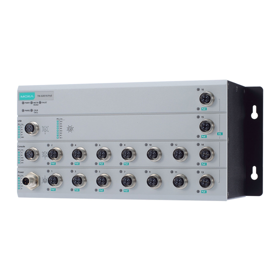
Overview The ToughNet TN-G4500 Series of M12 managed Ethernet switches are designed for railway applications, including rolling stock and wayside installations. The switches use M12 and other circular connectors to ensure tight, robust connections, and guarantee reliable operation in industrial environments where vibration and shock are commonplace. -
Page 3: Recommended Optional Accessories
• EtherNet/IP and Modbus/TCP industrial Ethernet protocols supported • Port-based VLAN, IEEE 802.1Q VLAN, and GVRP to ease network planning • QoS (IEEE 802.1p/1Q and ToS/DiffServ) allows real-time traffic classification and prioritization • IEEE 802.3ad, LACP for optimum bandwidth utilization •... -
Page 4: Panel Layouts
Panel Layouts 1. PWR1 LED: for power input 1 2. MSTR/HEAD LED: for ring master or chain head 3. FAULT LED 4. 10/100/1000BaseT(X) port (M12 X-coded 8-pin female connector) 5. 10/100/1000BaseT(X) port LED 6. 10G BaseT(X) port LED 7. 10G BaseT(X) port (M12 X-coded 8-pin female connector) 8. -
Page 5: Mounting Dimensions (Unit = Mm)
Mounting Dimensions (unit = mm) Panel/Wall Mounting STEP 1: Mounting the TN-G4500 to a wall requires 4 screws. Use the ToughNet switch as a guide to mark the correct positions of the 4 screws. STEP 2: Use the 4 screws in the panel mounting kit. -
Page 6: Wiring Requirements
NOTE Before tightening the screws into the wall, make sure the screw head and shaft size are suitable by inserting the screw through one of the keyhole-shaped apertures of the ToughNet switch. STEP 3: Once the screws are fixed in the wall, hang the ToughNet switch on the 4 screws through the large opening of the keyhole- shaped apertures, and then slide the switch downwards. -
Page 7: Connecting The Power Supplies
Connecting the Power Supplies The ToughNet TN-G4500 Series switches support dual power inputs— power input 1 and power input 2. The M12 K-coded 5-pin male connector on the TN-G4500 Series switches' front panel is used for the dual power inputs. -
Page 8: Connecting The Serial Port
Pinouts for the power input port V1– V2– Description Usage Connect “PWR1 Live / DC +” to the positive (+) PWR1 / DC + terminal when using a DC power source. Connect “PWR1 Neutral / DC –” to the negative PWR1 / DC –... -
Page 9: Connecting The Data Lines
Connecting the USB Storage Port The TN-G4500 Series has a M12 A-coded 5-pin female connector. Users can either use an adapter or the ABC-02-P-USB-M12 to connect to a PC or to import configuration files to the device. Connecting the Data Lines Ethernet Port Connection The TN-G4500 Series has 12 10/100/1000BaseT(X) Ethernet ports (M12 X-coded 8-pin female connector) and 4 10G BaseT(X) Ethernet... - Page 10 M12 (8-pin, M) to M12 (8-pin, M) Cross-Over Cable Wiring M12 (8-pin, M) to M12 (8-pin, M) Straight-Trough Cable Wiring M12 (8-pin, M) to RJ45 (8-pin) Cross-Over Cable Wiring - 10 -...
-
Page 11: Led Indicators
M12 (8-pin, M) to RJ45 (8-pin) Straight-Trough Cable Wiring LED Indicators Several LED indicators are located on the ToughNet switch’s front panel. The function of each LED is described in the table below. Color State Description System LEDs Power is being supplied to power input PWR1. - Page 12 Color State Description path in this Turbo Ring, or it is the Tail of this Turbo Chain. Blinking When Turbo Chain is down. When the TN switch disables the coupling function of Turbo Ring, or it is not the Tail of the Turbo Chain. FAULT + Rotate Blinking When ABC-02 is importing or...
Need help?
Do you have a question about the ToughNet TN-G4500 Series and is the answer not in the manual?
Questions and answers