Table of Contents
Advertisement
Available languages
Available languages
Quick Links
Advertisement
Chapters
Table of Contents

Subscribe to Our Youtube Channel
Related Manuals for PROEL DREAMLIGHT 250 ECLIPSE WASH


Summary of Contents for PROEL DREAMLIGHT 250 ECLIPSE WASH
- Page 1 DREAMLIGHT 250 ECLIPSE WASH PLML250E...
-
Page 2: Table Of Contents
INDICE INTRODUZIONE ............... 2 CARATTERISTICHE..............2 NORME DI SICUREZZA............4 CONDIZIONI OPERATIVE............5 INSTALLAZIONE / SOSTITUZIONE LAMPADA ....6 REGOLAZIONE LAMPADA ............ 8 INSTALLAZIONE............... 9 CONNESSIONE DMX.............10 CONNESSIONE ALLA RETE DI ALIMENTAZIONE..11 FUNZIONI CANALI..............12 INDIRIZZAMENTO ..............14 FUNZIONI MENU DISPLAY..........14 CARATTERISTICHE TECNICHE..........17 PULIZIA E MANUTENZIONE ..........18 SOSTITUZIONE FUSIBILE.............18 Tutte le specifiche riportate nel presente manuale sono soggette a variazioni... -
Page 3: Introduzione
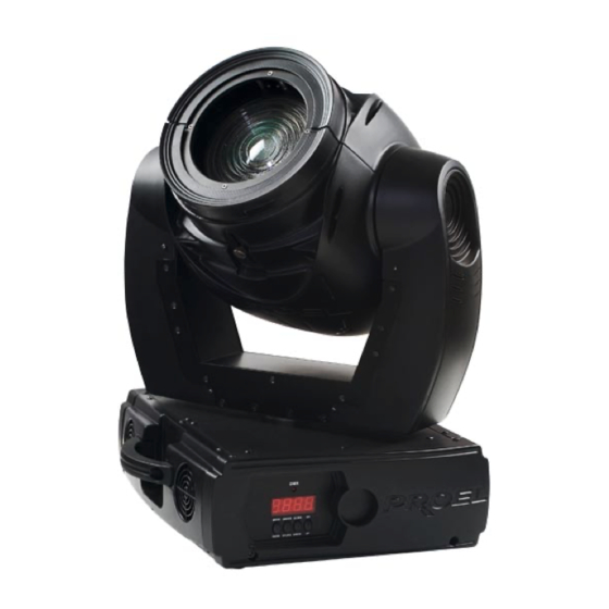
ATTENZIONE TENERE QUESTO APPARECCHIO LONTANO DA PIOGGIA E UMIDITÀ. SCOLLEGARE IL CAVO DALLA RETE DI ALIMENTAZIONE PRIMA DI APRIRE IL COPERCHIO. PER LA VOSTRA SICUREZZA, LEGGERE ATTENTAMENTE QUESTO MANUALE PRIMA DI ACCENDERE L’APPARECCHIO PER LA PRIMA VOLTA. Chiunque si occupi dell’installazione, uso e manutenzione di questo apparecchio deve: - essere una persona qualificata - seguire le istruzioni riportate sul presente manuale. - Page 4 1: Guida dello zoom manuale 2: Testa mobile 3: Coperchio portalampada 4: Maniglia per la movimentazione 5: Display LED...
-
Page 5: Norme Di Sicurezza
NORME DI SICUREZZA ATTENZIONE: PRESTARE PARTICOLARE ATTENZIONE ALLE OPERAZIONI DA EFFETTUARE. CON L’ALTA TENSIONE POTRESTE SUBIRE PERICOLOSI SHOCK ELETTRICI TOCCANDO I CAVI. Questo apparecchio ha lasciato i nostri stabilimenti in condizioni assolutamente perfette. Per mantenerle tali e per effettuare operazioni in sicurezza, è importante che l’utente segua le istruzioni di sicurezza e gli avvertimenti riportati in questo manuale utente. -
Page 6: Condizioni Operative
RISCHI PER LA SALUTE: non guardare mai direttamente all’interno della sorgente di luce, persone sensibili potrebbero avere uno shock epilettico. Non accendere e spegnere in ristretti intervalli di tempo perché ciò riduce il tempo di vita della lampada considerate che danni causati da modifiche manuali all’apparecchio non sono soggetti a garanzia. -
Page 7: Installazione / Sostituzione Lampada
Fissare sempre l’apparecchio con un’adeguata fune di sicurezza. Fissare tale fune tramite il corretto punto di fissaggio al di sotto della base e non tramite le maniglie di trasporto. Mettere in funzione l’apparecchio solo dopo essersi assicurati che la scocca esterna sia saldamente chiusa e tutte le viti siano correttamente serrate. - Page 8 Utilizzare lampade HSR250/MSR250 o equivalenti, rispettandone le specifiche del costruttore. ATTENZIONE: la lampada deve essere sostituita quando è danneggiata o deformata a causa del calore. Durante il normale funzionamento, la lampada raggiunge temperature superiori a 600°C. Prima di sostituire la lampada, scollegare l’alimentazione e attendere che la stessa si raffreddi (circa 10 min.) Durante l’installazione della nuova lampada non toccare il bulbo in vetro con le mani nude.
-
Page 9: Regolazione Lampada
PROCEDIMENTO Svitare le viti di fissaggio (X, Y, Z) del coperchio del portalampada con un giravite a croce e rimuovere tale coperchio. Inserire la lampada nuova nel portalampada facendo attenzione a non avere un contatto diretto del bulbo con le dita. Riavvitare il coperchio del porta lampada. -
Page 10: Installazione
Se l’impronta è più luminosa intorno al bordo rispetto al centro, o la luminosità è bassa, la lampada è troppo vicina al fondo della parabola. Spingere la lampada girando le tre viti in senso antiorario ¼ di giro alla volta fino a quando la luminosità... -
Page 11: Connessione Dmx
ATTENZIONE: proiettore potrebbe provocare gravi danni in caso di caduta. In presenza di qualsiasi dubbio riguardante la sicurezza della possibile installazione, non installare il proiettore. RISCHIO INCENDIO: momento dell’installazione del proiettore assicurarsi che non ci siano superfici infiammabili a distanza inferiore a 1 m ATTENZIONE: Usare 2 ganci appropriati per fissare l’apparecchio ad una truss. -
Page 12: Connessione Alla Rete Di Alimentazione
SCHEMA DI CONNESSIONE DEI CAVI DMX: DMX-input DMX-output spina XLR presa XLR Utilizzando centraline DMX con questo schema per i connettori, è possibile connettere l’uscita DMX della centralina all’ingresso DMX del primo proiettore della catena DMX. Se si desidera connettere una centralina DMX con un altro tipo di uscita XLR (es. -
Page 13: Funzioni Canali
Cavo Simbolo marrone fase neutro giallo/verde terra La terra deve essere connessa. Il proiettore non deve essere connesso ad un dimmer-pack. FUNZIONI CANALI. CANALE 1: MOVIMENTO ORIZZONTALE (PAN). Portare su il relativo slider per muovere orizzontalmente la testa (PAN). La testa può essere ruotata di 530° e può essere fermata in qualsiasi posizione intermedia desiderata. - Page 14 CANALE 7: RUOTA COLORI. La ruota colori è composta dai seguente colori Bianco Rosso Giallo Viola Verde Arancione Rosa Blu scuro Filtro temperatura 6200 K Rainbow CANALE 8: FROST. Tramite il canale 8 è possibile dare un effetto Frost al fascio luminoso oppure deformare la forma del fascio con una forma lineare con la possibilità...
-
Page 15: Indirizzamento
CANALE 13: DIMMER. Questo canale regola linearmente l’apertura delle palette dello shutter dal blackout totale all’apertura completa dello shutter. INDIRIZZAMENTO Il Pannello di controllo sul lato anteriore del PLML250E vi permette di assegnare all’apparecchio l’indirizzo DMX dal quale l’apparecchio risponderà al controllore. - Page 16 Tramite questa funzione è possibile invertire il verso di rotazione del movimento TILT Reverse TILT Reverse TILT Reverse TILT Reverse MODE MODE MODE MODE del TILT. Per attivare la modalità , premere il tasto ENTER ENTER ENTER ENTER posizionarsi alla voce .
- Page 17 Note: Dopo avere acceso il proiettore, lo stesso controllerà automaticamente se sta ricevendo i dati dal DMX o no. Se non ci sono dati in input sul display inizierà a lampeggiare “A001” cioè l’indirizzo attualmente settato. Questa situazione avviene se: Il connettore DMX in ingresso al proiettore o il connettore in uscita dalla centralina non sono connessi, oppure la centralina è...
-
Page 18: Caratteristiche Tecniche
CARATTERISTICHE TECNICHE 230V / 50Hz Alimentazione (120V / 60Hz) Potenza assorbita 300 W Canali DMX Connessione DMX XLR 3 poli Lunghezza 380 mm Larghezza 315mm Altezza 510 mm Peso netto 30 kg Massima temperatura ambiente 40 °C Massima temperatura dell’apparecchio 90 °C Distanza minima... -
Page 19: Pulizia E Manutenzione
- Rimuovere il vecchio fusibile dall’alloggiamento - Inserire il nuovo fusibile - Riposizionare il coperchio nell’alloggiamento USARE SEMPRE RICAMBI ORIGINALI PROEL. Se il cavo di alimentazione presenta segni di usura o danni, deve essere sostituito con un cavo nuovo disponibile presso il vostro rivenditore. - Page 20 CONTENTS INTRODUCTION ..............20 FEATURES ................20 SAFETY INSTRUCTIONS ............22 OPERATING CONDITION.............23 LAMP INSTALLATION / REPLACEMENT ......24 LAMP ADJUSTMENT.............25 RIGGING ...................26 DMX-CONNECTION ..............27 CONNECTION WITH THE MAINS........28 CHANNELS CONTROL............29 ADDRESSING ................31 DISPLAY FUNCTION..............31 TECHNICAL SPECIFICATIONS ..........33 CLEANING AND MAINTENANCE........34 FUSE REPLACING..............34...
-
Page 21: Introduction
CAUTION KEEP THIS DEVICE AWAY FROM RAIN AND MOISTURE! UNPLUG MAINS LEAD BEFORE OPENING THE HOUSING! FOR YOUR OWN SAFETY, PLEASE READ THIS USER MANUAL CAREFULLY BEFORE YOU INITIAL START - UP! Every person involved with the installation, operation and maintenance of this device have to: Be qualified Follow the instructions of this manual... - Page 22 1: Driving line for manual zoom 2: Moving head 3: Lamp’s cover 4: Handle for handling operation 5: LED Display...
-
Page 23: Safety Instructions
SAFETY INSTRUCTIONS CAUTION: BE CAREFUL WITH YOUR OPERATIONS. WITH A DANGEROUS VOLTAGE YOU CAN SUFFER A DANGEROUS ELECTRIC SHOCK WHEN TOUCHING THE WIRES. This device has left our premises in absolutely perfect condition. In order to maintain this condition and to ensure a safe operation, it is absolutely necessary for the user to follow the safety instructions and warning notes written in this user manual. -
Page 24: Operating Condition
HEALTH HAZARD: Never look directly into the light source, as sensitive persons may suffer an epileptic shock (especially meant for epileptics)! Do not switch the device on and off in short intervals as this would reduce the lamp’s life. Please consider that damages caused by manual modifications to the device are not subject to warranty. -
Page 25: Lamp Installation / Replacement
The lamp must never be ignited if the objective-lens or any housing-cover is open, as discharge lamps may explode and emit a high ultraviolet radiation, which may cause burns. The maximum ambient temperature (T = 40°C) must never be exceeded. CAUTION: The lens has to be replaced when it is obviously damaged, so that its function is impaired, e. -
Page 26: Lamp Adjustment
During the installation do not touch the glass bulb bare-handed. Please follow the lamp manufacturer’s notes. Do not install lamps with a higher wattage. Lamps with a higher wattage generate temperatures that the device was not designed for. Damages caused by non observance are not subject to warranty. -
Page 27: Rigging
RIGGING DANGER TO LIFE: Please consider the respective national norms during the installation. The installation must only be carried out by an authorized dealer. The installation must always be secured with a secondary safety attachment, e.g. an appropriate catch net. This secondary safety attachment must be constructed in a way that no part of the installation can fall down if the main attachment fails. -
Page 28: Dmx-Connection
DANGER OF FIRE: when installing the device, make sure there is no highly- inflammable material (decoration articles, etc.) within a distance of min. 1 m. CAUTION! Use 2 appropriate clamps to rig the fixture on the truss. Screw one clamp each via a M12 screw and nut onto the omega holders. -
Page 29: Connection With The Mains
DIAGRAM OF THE XLR-CONNECTION: DMX-output DMX-input XLR socket XLR socket If you are using the recommended controllers, you can connect the DMX-output of the controller directly with the DMX-input of the first fixture in the DMX-chain. If you wish to connect DMX controllers with other XLR-outputs, you need to use adapter-cables. -
Page 30: Channels Control
Cable International brown live blue neutral yellow earth green The earth has to be connected. Lighting effects must not be connected to dimming-packs. CHANNELS CONTROL CHANNEL 1 - HORIZONTAL MOVEMENT (PAN). Move up the first slider to move head horizontally (PAN). - Page 31 CHANNEL 7 - COLOR WHEEL. White Yellow Purple Green Orange Blue Pink Deep blue 6200 K filter Rainbow CHANNEL 8 – FROST The 8 slider controls the shape of the light beam. You can create a frost effect or give a linear shape to the light beam. Beam shaper allows to index the degree of the rotation within 180°.
-
Page 32: Addressing
CHANNEL 13 – DIMMER This channel controls the aperture of the shutter. You can control linearly the opening movement from total black to total open. ADDRESSING The Control Board on the front side of the PLML250E allows you to assign the DMX fixture address, which is defined as the first channel from which the PLML250E will respond to the controller. - Page 33 DEMO OPERATION The PLML250E moving head works also without a connection to an external controller. Press the MODE MODE MODE MODE button and select to enter into the Demo Operation mode. Press UP UP button and when the display shows .
-
Page 34: Technical Specifications
TECHNICAL SPECIFICATIONS 230V / 50Hz Power supply (117V / 60Hz) Power consumption 300 W DMX channels DMX connector 3-pole XLR Length 380 mm Width 315 mm Height 510 mm Net weight 30 kg Maximum ambient temperature 40 °C Maximum housing temperature 90 °C Minimum distance... -
Page 35: Cleaning And Maintenance
CLEANING AND MAINTENANCE CAUTION: Disconnect from mains before starting maintenance operation! It is absolutely essential that the fixture is kept clean and that dust, dirt and smoke-fluid residues must not build up on or within the fixture. Otherwise, the fixture‘s light-output will be significantly reduced. Regular cleaning will not only ensure the maximum light-output, but will also allow the fixture to function reliably throughout its life. - Page 36 PERSONALITY TAB CHANNEL DMX VALUE FUNCTION 0-255 TILT 0-255 tilt PAN FINE 0-255 pan 16bit TILT FINE 0-255 tilt 16bit 0-249 pan/tilt speed (from fast to slow) PAN/TILT SPEED 250-252 max speed 253-255 blackout during the movement RESET 200-210 reset 0-12 white 13-25...
Need help?
Do you have a question about the DREAMLIGHT 250 ECLIPSE WASH and is the answer not in the manual?
Questions and answers