ZyXEL Communications VMG Series User Manual
Rsl router
Hide thumbs
Also See for VMG Series:
- User manual (434 pages) ,
- User manual (520 pages) ,
- User manual (424 pages)

Related Manuals for ZyXEL Communications VMG Series


Summary of Contents for ZyXEL Communications VMG Series
- Page 1 User’s Guide VMG/XMG Series DSL Router Default Login Details Version 5.13 Edition 2, 10/2018 LAN IP Address http://192.168.1.1 admin Login Password See the device label Copyright © 2018 Zyxel Communications Corporation...
- Page 2 IMPORTANT! READ CAREFULLY BEFORE USE. KEEP THIS GUIDE FOR FUTURE REFERENCE. This is a User’s Guide for a series of products. Not all products support all features. Screenshots and graphics in this book may differ slightly from what you see due to differences in your product firmware or your computer operating system.
-
Page 3: Table Of Contents
Contents Overview Contents Overview User’s Guide ............................16 Introducing the Zyxel Device ......................17 The Web Configurator ......................... 34 Quick Start ............................. 42 Tutorials ..............................48 Technical Reference ........................80 Connection Status Screens ......................... 81 Broadband ............................93 Wireless ..............................121 Home Networking ..........................151 Routing .............................. - Page 4 Contents Overview SNMP ..............................320 Time Settings ............................323 E-mail Notification ..........................325 Log Setting ............................327 Firmware Upgrade ..........................331 Backup Restore ........................... 334 Diagnostic ............................337 Troubleshooting ..........................343 Appendices .............................349 VMG/XMG Series User’s Guide...
-
Page 5: Table Of Contents
Table of Contents Table of Contents Contents Overview ..........................3 Table of Contents ..........................5 Part I: User’s Guide..................16 Chapter 1 Introducing the Zyxel Device ......................17 1.1 Overview ............................17 1.1.1 Internet Access ........................18 1.1.2 G.fast ............................18 1.1.3 Ethernet WAN ........................19 1.1.4 Triple Play .......................... - Page 6 Table of Contents 3.4.1 Internet Status ........................43 3.4.2 Successful Internet Connection ..................44 3.4.3 Unsuccessful Internet Connection ..................44 3.4.4 Incorrect Internet Information ..................... 45 3.4.5 Encapsulation ........................45 3.4.6 Internet Information Input ....................46 3.5 Quick Start Setup-Wireless ......................46 3.6 Quick Start Setup-Finish ........................
- Page 7 Table of Contents 5.1.3 The Wi-Fi Settings Screen ...................... 84 5.1.4 The Guest Wi-Fi Settings Screen ................... 86 5.1.5 The LAN Screen ........................88 5.1.6 The Parental Control Screen ....................89 Chapter 6 Broadband............................93 6.1 Overview ............................93 6.1.1 What You Can Do in this Chapter ..................93 6.1.2 What You Need to Know .....................
- Page 8 Table of Contents Chapter 8 Home Networking ..........................151 8.1 Home Networking Overview ....................... 151 8.1.1 What You Can Do in this Chapter ..................151 8.1.2 What You Need To Know ....................152 8.1.3 Before You Begin ......................... 153 8.2 The LAN Setup Screen ........................ 153 8.3 The LAN Static DHCP Screen .....................
- Page 9 Table of Contents 10.7 The QoS Policer Setup Screen ....................188 10.7.1 Add/Edit a QoS Policer ....................189 10.8 Technical Reference ........................190 Chapter 11 Network Address Translation (NAT) ....................195 11.1 NAT Overview ..........................195 11.1.1 What You Can Do in this Chapter ................... 195 11.1.2 What You Need To Know ....................
- Page 10 Table of Contents 14.2 The Vlan Group Screen ......................220 14.2.1 Add/Edit a VLAN Group ....................221 Chapter 15 Interface Grouping ..........................222 15.1 Interface Grouping Overview ....................222 15.1.1 What You Can Do in this Chapter ................... 222 15.2 The Interface Grouping Screen ....................222 15.2.1 Interface Group Configuration ..................
- Page 11 Table of Contents Chapter 20 Parental Control ..........................246 20.1 Parental Control Overview ....................... 246 20.2 The Parental Control Screen ..................... 246 20.2.1 Add/Edit a Parental Control Profile ................247 Chapter 21 Scheduler Rule ..........................252 21.1 Scheduler Rule Overview ......................252 21.2 The Scheduler Rule Screen ......................
- Page 12 Table of Contents Chapter 24 Log ..............................291 24.1 Log Overview ..........................291 24.1.1 What You Can Do in this Chapter ................... 291 24.1.2 What You Need To Know ....................291 24.2 The System Log Screen ......................292 24.3 The Security Log Screen ......................292 Chapter 25 Traffic Status .............................294 25.1 Traffic Status Overview ......................
- Page 13 Table of Contents 31.1 WLAN Station Status Overview ....................309 Chapter 32 Cellular Statistics ..........................311 32.1 Cellular Statistics Overview ....................... 311 32.2 The Cellular Statistics Screen ..................... 311 Chapter 33 System...............................313 33.1 System Overview ........................313 33.2 The System Screen ........................313 Chapter 34 User Account............................314 34.1 User Account Overview ......................
- Page 14 Table of Contents 39.1 Logs Setting Overview ....................... 327 39.2 The Log Settings Screen ......................327 39.2.1 Example E-mail Log ......................329 Chapter 40 Firmware Upgrade ...........................331 40.1 Firmware Upgrade Overview ....................331 40.2 The Firmware Screen ........................331 Chapter 41 Backup Restore ..........................334 41.1 Backup Restore Overview ......................
- Page 15 Table of Contents Appendix E Legal Information ....................... 381 Index ..............................389 VMG/XMG Series User’s Guide...
-
Page 16: User's Guide
User’s Guide... -
Page 17: Introducing The Zyxel Device
H A P T E R Introducing the Zyxel Device 1.1 Overview The Zyxel Device is a wireless VDSL router and Gigabit Ethernet gateway. Zyxel Device refers to these models as outlined below. • VMG1312-B10D • XMG3927-B50A • VMG3312-T20A • VMG3927-Bx0A •... -
Page 18: Internet Access
Chapter 1 Introducing the Zyxel Device 1.1.1 Internet Access Your Zyxel Device provides shared Internet access by connecting the DSL port to the DSL or MODEM jack on a splitter or your telephone jack. You can have multiple WAN services over one ADSL or VDSL. The Zyxel Device cannot work in ADSL and VDSL mode at the same time. -
Page 19: Ethernet Wan
Chapter 1 Introducing the Zyxel Device G.FAST is the acronym for Fast Access to Subscriber Terminals, and the letter G stands for the ITU-T G series of recommendations. G.fast is a technology providing gigabit speeds over traditional copper twisted-pair wires. G.fast applies Fiber-To-The-distribution point (FTTdp) structure, which reuses the deployed copper wire for the final meters. -
Page 20: Wan Priority
Chapter 1 Introducing the Zyxel Device Figure 4 Triple Play Example 1.1.5 WAN Priority The WAN connection priority is as follows: Ethernet WAN G.fast/DSL Cellular WAN (3G/4G) Section 1.1.7 on page 21 for more information about Cellular backup. 1.1.6 Wireless Access The Zyxel Device is a wireless Access Point (AP) for IEEE 802.11b/g/n/a/ac wireless clients, such as notebook computers, iPads, smartphones, etc. -
Page 21: Zyxel Device's Usb Support
Chapter 1 Introducing the Zyxel Device 1.1.7 Zyxel Device’s USB Support The USB port of the Zyxel Device is used for cellular WAN backup, file-sharing, and media server. Cellular WAN (3G/4G) Backup Connect a supported cellular USB dongle with an active SIM card to the USB port. This adds a second WAN interface and allows the Zyxel Device to wirelessly access the Internet via a cellular network. -
Page 22: Voip Features
Chapter 1 Introducing the Zyxel Device Media Server You can also use the Zyxel Device as a media server. This lets anyone on your network play video, music, and photos from a USB device (B) connected to the Zyxel Device’s USB port (without having to copy them to another computer). -
Page 23: Good Habits For Managing The Zyxel Device
Chapter 1 Introducing the Zyxel Device 1.3 Good Habits for Managing the Zyxel Device Do the following things regularly to make the Zyxel Device more secure and to manage the Zyxel Device more effectively. • Change the password. Use a password that’s not easy to guess and that consists of different types of characters, such as numbers and letters. -
Page 24: Leds (Lights)
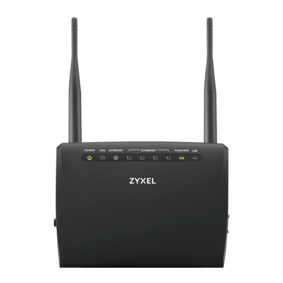
Chapter 1 Introducing the Zyxel Device 1.5 LEDs (Lights) None of the LEDs are on if the Zyxel Device is not receiving power. Table 4 VMG1312-B10D LED Descriptions COLOR STATUS DESCRIPTION POWER Green The Zyxel Device is receiving power and ready for use. Blinking The Zyxel Device is self-testing. - Page 25 Chapter 1 Introducing the Zyxel Device Table 5 VMG3312-T20A LED Descriptions (continued) COLOR STATUS DESCRIPTION ETHERNET1~4 Green The Zyxel Device has a successful 10/100 Mbps Ethernet connection with a device on the Local Area Network (LAN). Blinking The Zyxel Device is sending or receiving data to/from the LAN at 10/100 Mbps.
- Page 26 Chapter 1 Introducing the Zyxel Device Table 6 VMG3625-T20A LED Descriptions (continued) COLOR STATUS DESCRIPTION Green The VDSL line is up. Blinking The Zyxel Device is initializing the VDSL line. The DSL line is down. Orange The ADSL line is up. Slow The Zyxel Device is detecting carrier signals.
- Page 27 Chapter 1 Introducing the Zyxel Device Table 7 VMG3925-B10B LED Descriptions (continued) COLOR STATUS DESCRIPTION Green The VDSL line is up. Blinking The Zyxel Device is initializing the VDSL line. Orange The ADSL line is up. Blinking The Zyxel Device is initializing the ADSL line. The DSL line is down.
- Page 28 Chapter 1 Introducing the Zyxel Device Table 8 VMG3925-B10C LED Descriptions COLOR STATUS DESCRIPTION Power Green The Zyxel Device is receiving power and ready for use. Blinking The Zyxel Device is self-testing. The Zyxel Device detected an error while self-testing, or there is a device malfunction.
- Page 29 Chapter 1 Introducing the Zyxel Device Table 8 VMG3925-B10C LED Descriptions (continued) COLOR STATUS DESCRIPTION Green The Zyxel Device recognizes a USB connection through the USB1 slot. Blinking The Zyxel Device is sending/receiving data to /from the USB device connected to it. The Zyxel Device does not detect a USB connection through the USB1 slot.
- Page 30 Chapter 1 Introducing the Zyxel Device Table 10 VMG8823-BX0B LED Descriptions COLOR STATUS DESCRIPTION Power Green The Zyxel Device is receiving power and ready for use. Blinking The Zyxel Device is self-testing. The Zyxel Device detected an error while self-testing, or there is a device malfunction.
- Page 31 Chapter 1 Introducing the Zyxel Device Table 10 VMG8823-BX0B LED Descriptions (continued) COLOR STATUS DESCRIPTION Phone1, Green A SIP account is registered for the phone port. Phone2 Blinking A telephone connected to the phone port has its receiver off of the hook or there is an incoming call.
-
Page 32: Using The Wlan And Wps Buttons
Chapter 1 Introducing the Zyxel Device Table 11 VMG8924-B10D LED Descriptions (continued) COLOR STATUS DESCRIPTION LAN1~4 Green The Zyxel Device has a successful 10/100/1000 Mbps Ethernet connection with a device on the Local Area Network (LAN). Blinking The Zyxel Device is sending or receiving data to/from the LAN at 10/100/ 1000 Mbps. -
Page 33: The Reset Button
Chapter 1 Introducing the Zyxel Device See the following table to see how long you need to press the WLAN and WPS buttons on the Zyxel Device. Table 12 WLAN and WPA Buttons MODEL WLAN BUTTON WPS BUTTON VMG1312-B10D One second Two seconds VMG3312-T20A More than two seconds... -
Page 34: The Web Configurator
H A P T E R The Web Configurator 2.1 Overview The web configurator is an HTML-based management interface that allows easy setup and Zyxel Device management via Internet browser. Use Internet Explorer 8.0 and later versions or Mozilla Firefox 3 and later versions or Safari 2.0 and later versions. - Page 35 Chapter 2 The Web Configurator The following screen displays when you log into the web configurator for the first time. Enter a new password, retype it to confirm, and click Change password. If you prefer to use the default password, click Skip.
-
Page 36: Web Configurator Layout
Chapter 2 The Web Configurator 2.2 Web Configurator Layout Figure 13 Screen Layout As illustrated above, the main screen is divided into these parts: • A - Settings Icon (Navigation Panel & Side Bar) • B - Widget Icon • C - Main Window 2.2.1 Settings Icon Click this icon ( to see the side bar and navigation panel. - Page 37 Chapter 2 The Web Configurator The icons provide the following functions. Table 14 Web Configurator Icons in the Title Bar ICON DESCRIPTION Wizard: Click this icon to open screens where you can configure the Zyxel Device’s time zone Internet access, and wireless settings. See Chapter 3 on page 42 for more information about the Wizard screens.
- Page 38 Chapter 2 The Web Configurator Table 15 Navigation Panel Summary (continued) LINK FUNCTION Wireless General Use this screen to configure the wireless LAN settings and WLAN authentication/security settings. Guest/More AP Use this screen to configure multiple BSSs on the Zyxel Device. Use this screen to block or allow wireless traffic from wireless devices of Authentication certain SSIDs and MAC addresses to the Zyxel Device.
- Page 39 Chapter 2 The Web Configurator Table 15 Navigation Panel Summary (continued) LINK FUNCTION DNS Entry Use this screen to view and configure DNS routes. Dynamic DNS Use this screen to allow a static hostname alias for a dynamic IP address. IGMP/MLD IGMP/MLD Use this screen to configure multicast settings (IGMP for IPv4 and MLD for...
- Page 40 Chapter 2 The Web Configurator Table 15 Navigation Panel Summary (continued) LINK FUNCTION System Log Use this screen to view the status of events that occurred to the Zyxel Device. You can export or e-mail the logs. Security Log Use this screen to view all security related events. You can select level and category of the security events in their proper drop-down list window.
-
Page 41: Widget Icon
Chapter 2 The Web Configurator Table 15 Navigation Panel Summary (continued) LINK FUNCTION Email E-mail Use this screen to configure up to two mail servers and sender addresses Notification Notification on the Zyxel Device. Log Setting Log Setting Use this screen to change your Zyxel Device’s log settings. Firmware Firmware Use this screen to upload firmware to your Zyxel Device. -
Page 42: Quick Start
H A P T E R Quick Start 3.1 Overview Use the Wizard screens to configure the Zyxel Device’s time zone, basic Internet access, and wireless settings. Note: See the technical reference chapters (starting on Chapter 4 on page 48) for background information on the features in this chapter. -
Page 43: Internet
Chapter 3 Quick Start Figure 15 Wizard - Time Zone 3.4 Internet Connect an Ethernet cable, a DSL cable, or a USB dongle for Internet access. See Section 1.1.5 on page for more information about WAN priority. The Zyxel Device will check the Internet status automatically, and determine your connection type. -
Page 44: Successful Internet Connection
Chapter 3 Quick Start Figure 17 Wizard - Internet Check 3.4.2 Successful Internet Connection The Zyxel Device has Internet access. Figure 18 Wizard - Successful WAN Connection 3.4.3 Unsuccessful Internet Connection The Zyxel Device didn’t detect a WAN connection. Connect an Ethernet cable, a DSL cable, or a USB dongle for Internet access if you haven’t connected any. -
Page 45: Incorrect Internet Information
Chapter 3 Quick Start Figure 19 Wizard - WAN Connection is Down 3.4.4 Incorrect Internet Information The Internet connection information is incorrect. Click Next to configure the Internet settings. Figure 20 Wizard - Incorrect Internet Information 3.4.5 Encapsulation Select the encapsulation type your ISP uses. VMG/XMG Series User’s Guide... -
Page 46: Internet Information Input
Chapter 3 Quick Start Figure 21 Wizard - Incorrect Internet Information 3.4.6 Internet Information Input Enter your Internet connection information if you select PPPoE as the encapsulation method. Click Next. Figure 22 Wizard - Internet Connection Information 3.5 Quick Start Setup-Wireless Turn the wireless LAN on or off. -
Page 47: Quick Start Setup-Finish
Chapter 3 Quick Start Figure 23 Wizard - Wireless 3.6 Quick Start Setup-Finish Your Zyxel Device saves your settings and attempts to connect to the Internet. VMG/XMG Series User’s Guide... -
Page 48: Tutorials
H A P T E R Tutorials 4.1 Overview This chapter shows you how to use the Zyxel Device’s various features. • Setting Up an ADSL PPPoE Connection, see page 48 • Setting Up a Secure Wireless Network, see page 51 •... - Page 49 Chapter 4 Tutorials In this example, the DSL connection has the following information. General Name MyDSLConnection Type ADSL over ATM Connection Mode Routing Encapsulation PPPoE IPv6/IPv4 Mode IPv4 ATM PVC Configuration VPI/VCI 36/48 Encapsulation Mode LLC/SNAP-Bridging Service Category UBR without PCR Account Information PPP User Name 1234@DSL-Ex.com...
- Page 50 Chapter 4 Tutorials You should see a summary of your new DSL connection setup in the Broadband screen as follows. VMG/XMG Series User’s Guide...
-
Page 51: Setting Up A Secure Wireless Network
Chapter 4 Tutorials Try to connect to a website to see if you have correctly set up your Internet connection. Be sure to contact your service provider for any information you need to configure the WAN screens. 4.3 Setting Up a Secure Wireless Network Thomas wants to set up a wireless network so that he can use his notebook to access the Internet. - Page 52 Chapter 4 Tutorials Click Network Setting > Wireless to open the General screen. Select More Secure as the security level and WPA2-PSK as the security mode. Configure the screen using the provided parameters (see page 51). Click Apply. VMG/XMG Series User’s Guide...
- Page 53 Chapter 4 Tutorials Go to the Wireless > Others screen and select 802.11b/g/n Mixed in the 802.11 Mode field. Click Apply. VMG/XMG Series User’s Guide...
-
Page 54: Using Wps
Chapter 4 Tutorials Thomas can now use the WPS feature to establish a wireless connection between his notebook and the Zyxel Device (see Section 4.3.2 on page 54). He can also use the notebook’s wireless client to search for the Zyxel Device (see Section 4.3.3 on page 58). - Page 55 Chapter 4 Tutorials Note: Your Zyxel Device has a WPS button located on its side panel as well as a WPS button in its configuration utility. Both buttons have exactly the same function: you can use one or the other. Note: It doesn’t matter which button is pressed first.
- Page 56 Chapter 4 Tutorials Figure 24 Example WPS Process: PBC Method Wireless Client WITHIN 2 MINUTES SECURITY INFO COMMUNICATION Example WPS Process: PBC Method PIN Configuration When you use the PIN configuration method, you need to check the client’s PIN number and use the Zyxel Device’s configuration interface.
- Page 57 Chapter 4 Tutorials Enter the PIN number of the wireless client and click the Register button. Activate WPS function on the wireless client utility screen within two minutes. The Zyxel Device authenticates the wireless client and sends the proper configuration settings to the wireless client.
-
Page 58: Without Wps
Chapter 4 Tutorials Figure 25 Example WPS Process: PIN Method Wireless Client Enter WPS PIN from other device: START WITHIN 2 MINUTES Authentication by PIN SECURITY INFO COMMUNICATION Example WPS Process: PIN Method 4.3.3 Without WPS Use the wireless adapter’s utility installed on the notebook to search for the “Example” SSID. Then enter the “DoNotStealMyWirelessNetwork”... -
Page 59: Setting Up Multiple Wireless Groups
Chapter 4 Tutorials 4.4 Setting Up Multiple Wireless Groups Company A wants to create different wireless network groups for different types of users as shown in the following figure. Each group has its own SSID and security mode. • Employees in Company A will use a general Company wireless network group. •... - Page 60 Chapter 4 Tutorials Click Network Setting > Wireless > Guest/More AP to open the following screen. Click the Edit icon to configure the second wireless network group. VMG/XMG Series User’s Guide...
- Page 61 Chapter 4 Tutorials Configure the screen using the provided parameters and click Apply. In the Guest/More AP screen, click the Edit icon to configure the third wireless network group. Configure the screen using the provided parameters and click Apply. VMG/XMG Series User’s Guide...
- Page 62 Chapter 4 Tutorials Check the status of VIP and Guest in the Guest/More AP screen. The yellow bulbs signify that the SSIDs are active and ready for wireless access. VMG/XMG Series User’s Guide...
-
Page 63: Using The File Sharing Feature
Chapter 4 Tutorials 4.5 Using the File Sharing Feature In this section you can: • Set up file sharing of your USB device from the Zyxel Device. • Access the shared files of your USB device from a computer. 4.5.1 Set Up File Sharing To set up file sharing you need to connect your USB device, enable file sharing and set up your share(s). - Page 64 Chapter 4 Tutorials Click Add New Share in the File Sharing screen to add a new share. Select your USB device from the Volume drop-down list box. Click Browse to browse through all the files on your USB device. Select the folder that you want to add as a share.
-
Page 65: Access Your Shared Files From A Computer
Chapter 4 Tutorials After you create a new user account, the screen should look like the following. 4.5.2 Access Your Shared Files From a Computer You can use Windows Explorer to access the file storage devices connected to the Zyxel Device. Note: The examples in this User’s Guide show you how to use Microsoft’s Windows 7 to browse your shared files. -
Page 66: Configuring The Zyxel Device
Chapter 4 Tutorials Before you begin, connect the USB storage device containing the media files you want to play to the USB port of your Zyxel Device. 4.6.1 Configuring the Zyxel Device To use your Zyxel Device as a media server, click Network Setting > USB Service > Media Server. Enable Media Server, select an interface on which you want to enable the media server function, enter the path clients use to access the media files on a USB storage device connected to the Zyxel Device, and click Apply. - Page 67 Chapter 4 Tutorials If you cannot see the Zyxel Device in the left panel as shown above, go to Organize > Manage Libraries > Music/Videos/Pictures/Recorded TV > Add > \\192.168.1.1\BobShare. (Select the folder containing the media you wish to upload to Windows Media Player.) In the right panel, you should see a list of files available in the USB storage device.
-
Page 68: Using A Digital Media Adapter
Chapter 4 Tutorials 4.6.3 Using a Digital Media Adapter This section shows you how you can use the Zyxel Device with a Zyxel DMA-2500 to play media files stored in the USB storage device in your TV screen. Note: For this tutorial, your DMA-2500 should already be set up with the TV according to the instructions in the DMA-2500 Quick Start Guide. -
Page 69: Configuring Static Route For Routing To Another Network
Chapter 4 Tutorials The screen shows you the list of available media files in the USB storage device. Select the file you want to open and push the Play button in the remote control. 4.7 Configuring Static Route for Routing to Another Network In order to extend your Intranet and control traffic flowing directions, you may connect a router to the Zyxel Device’s LAN. - Page 70 Chapter 4 Tutorials You need to specify a static routing rule on the Zyxel Device to specify R as the router in charge of forwarding traffic to N2. In this case, the Zyxel Device routes traffic from A to R and then R routes the traffic to B.
- Page 71 Chapter 4 Tutorials Table 16 IP Settings in this Tutorial DEVICE / COMPUTER IP ADDRESS 192.168.1.34 R’s N1 192.168.1.253 R’s N2 192.168.10.2 192.168.10.33 To configure a static route to route traffic from N1 to N2: Log into the Zyxel Device’s Web Configurator in advanced mode. Click Network Setting >...
-
Page 72: Configuring Qos Queue And Class Setup
Chapter 4 Tutorials Click OK. Now B should be able to receive traffic from A. You may need to additionally configure B’s firewall settings to allow specific traffic to pass through. 4.8 Configuring QoS Queue and Class Setup This section contains tutorials on how you can configure the QoS screen. Let’s say you are a team leader of a small sales branch office. - Page 73 Chapter 4 Tutorials QoS Example 10,000 kbps Your computer IP=192.168.1.23 and/or MAC=AA:FF:AA:FF:AA:FF A colleague’s computer Email traffic: Highest priority Other traffic: Automatic classifier Click Network Setting > QoS > General and click the QoS button to enable. When the switch turns blue ), the function is enabled.
- Page 74 Chapter 4 Tutorials Tutorial: Advanced > QoS > Queue Setup Click Network > QoS > Classification Setup > Add new Classification to create a new class. Select Enable in the Active field and follow the settings as shown in the screen below. VMG/XMG Series User’s Guide...
- Page 75 Chapter 4 Tutorials Tutorial: Advanced > QoS > Class Setup VMG/XMG Series User’s Guide...
-
Page 76: Access The Zyxel Device Using Ddns
Chapter 4 Tutorials Class Name Give a class name to this traffic, such as E-mail in this example. From Interface This is the interface from which the traffic will be coming from. Select LAN1 for this example. Ether Type Select IP to identify the traffic source by its IP address or MAC address. IP Address Type the IP address of your computer - 192.168.1.23. -
Page 77: Configuring Ddns On Your Zyxel Device
Chapter 4 Tutorials Add a new DDNS host name. This tutorial uses the following settings as an example. • Hostname: zyxelrouter.dyndns.org • Service Type: Host with IP address • IP Address: Enter the WAN IP address that your Zyxel Device is currently using. You can find the IP address on the Zyxel Device’s Web Configurator Status page. -
Page 78: Configuring The Mac Address Filter
Chapter 4 Tutorials 4.10 Configuring the MAC Address Filter Thomas noticed that his daughter Josephine spends too much time surfing the web and downloading media files. He decided to prevent Josephine from accessing the Internet so that she can concentrate on preparing for her final exams. -
Page 79: Access Your Shared Files From A Computer
Chapter 4 Tutorials 4.11 Access Your Shared Files From a Computer Here is how to use an FTP program to access a file storage device connected to the Zyxel Device’s USB port. Note: This example uses the FileZilla FTP program to browse your shared files. In FileZilla enter the IP address of the Zyxel Device (the default is 192.168.1.1), your account’s user name and password and port 21 and click Quickconnect. -
Page 80: Technical Reference
Technical Reference... -
Page 81: Connection Status Screens
H A P T E R Connection Status Screens 5.1 The Connection Status Screen After you log into the Web Configurator, the Connection Status screen appears. You can configure basic Internet access, wireless settings, and parental control settings in this screen. It also shows the network status of the Zyxel Device and computers/devices connected to it. -
Page 82: The System Info Screen
Chapter 5 Connection Status Screens Figure 28 Connectivity: Edit 5.1.2 The System Info Screen Use this screen to view the basic system information of the Zyxel Device. Figure 29 System Info Click the Arrow icon ( ) to view the more information on the status of your firewall and interfaces (WAN, LAN, and WLAN). - Page 83 Chapter 5 Connection Status Screens Figure 30 System Info: Detailed Information Each field is described in the following table. Table 17 System Info: Detailed Information LABEL DESCRIPTION Host Name This field displays the Zyxel Device system name. It is used for identification. Model Name This shows the model number of your Zyxel Device.
-
Page 84: The Wi-Fi Settings Screen
Chapter 5 Connection Status Screens Table 17 System Info: Detailed Information (continued) LABEL DESCRIPTION Encapsulation This field displays the current encapsulation method. IP Address This field displays the current IP address of the Zyxel Device in the WAN. Click the Release button to release the IP address provided by a DHCP server. IP Subnet Mask This field displays the current subnet mask in the WAN. - Page 85 Chapter 5 Connection Status Screens Figure 31 Wi-Fi Settings Click the Arrow icon ( ) to configure the SSIDs and/or passwords for your main wireless networks. Figure 32 Wi-Fi Settings: Configuration VMG/XMG Series User’s Guide...
-
Page 86: The Guest Wi-Fi Settings Screen
Chapter 5 Connection Status Screens Each field is described in the following table. Table 18 Wi-Fi Settings: Configuration LABEL DESCRIPTION Keep 2.4G and 5G Select this and the 2.4 GHz and 5 GHz wireless networks will use the same SSID. the same Note that you have to disable Zyxel MESH in the Network >... - Page 87 Chapter 5 Connection Status Screens Figure 33 Guest Wi-Fi Settings Click the Arrow icon ( ) to configure the SSIDs and/or passwords for your guest wireless networks. Figure 34 Guest Wi-Fi Settings: Configuration To assign different SSIDs for the 2.4 GHz and 5 GHz wireless networks, deselect Keep 2.4G and 5G the same in the Wi-Fi Settings screen, and the Guest Wi-Fi Settings screen will change.
-
Page 88: The Lan Screen
Chapter 5 Connection Status Screens Each field is described in the following table. Table 19 Wi-Fi Settings: Configuration LABEL DESCRIPTION WiFi Click this switch to enable or disable the 2.4 GHz and/or 5 GHz wireless networks. When the switch turns blue , the function is enabled. -
Page 89: The Parental Control Screen
Chapter 5 Connection Status Screens Figure 37 LAN Setup Each field is described in the following table. Table 20 Status Screen LABEL DESCRIPTION LAN IP Setup IP Address Enter the LAN IPv4 IP address you want to assign to your Zyxel Device in dotted decimal notation, for example, 192.168.1.1 (factory default). - Page 90 Chapter 5 Connection Status Screens Figure 38 Parental Control The Arrow icon is grayed out ( ) when the One Connect feature is enabled in the Network > Home Connectivity screen. This means you can’t configure parental control settings. If you click the grayed- out Arrow icon, the following message will appear.
- Page 91 Chapter 5 Connection Status Screens Table 21 Parental Control: Schedule (continued) LABEL DESCRIPTION Scheduled Profile This screen shows all the created profile(s). Blocked Devices The screen shows the profile devices that are not allowed to access the Internet. Click Add more Profile to create a profile. Use this screen to add a device(s) in a profile and block Internet access on the profile device(s).
- Page 92 Chapter 5 Connection Status Screens Each field is described in the following table. Table 23 Parental Control: Schedule LABEL DESCRIPTION Profile Name Enter a descriptive name for the profile. Internet Blocking Click this switch to enable or disable Internet access. When the switch turns blue , the function is enabled.
-
Page 93: Broadband
H A P T E R Broadband 6.1 Overview This chapter discusses the Zyxel Device’s Broadband screens. Use these screens to configure your Zyxel Device for Internet access. A WAN (Wide Area Network) connection is an outside connection to another network or the Internet. It connects your private networks, such as a LAN (Local Area Network) and other networks, so that a computer in one location can communicate with computers in other locations. -
Page 94: What You Need To Know
Chapter 6 Broadband Table 24 WAN Setup Overview LAYER-2 INTERFACE INTERNET CONNECTION CONNECTION DSL LINK TYPE MODE ENCAPSULATION CONNECTION SETTINGS ADSL over ATM Routing PPPoE/PPPoA ATM PVC configuration, PPP information, IPv4/IPv6 IP address, routing feature, DNS server, VLAN, QoS, and MTU IPoE/IPoA ATM PVC configuration, IPv4/IPv6 IP address, routing feature, DNS server,... - Page 95 Chapter 6 Broadband IPv6 Addressing The 128-bit IPv6 address is written as eight 16-bit hexadecimal blocks separated by colons (:). This is an example IPv6 address 2001:0db8:1a2b:0015:0000:0000:1a2f:0000. IPv6 addresses can be abbreviated in two ways: • Leading zeros in a block can be omitted. So 2001:0db8:1a2b:0015:0000:0000:1a2f:0000 can be written as 2001:db8:1a2b:15:0:0:1a2f:0.
- Page 96 Chapter 6 Broadband Figure 45 IPv6 Rapid Deployment Dual Stack Lite Use Dual Stack Lite when local network computers use IPv4 and the ISP has an IPv6 network. When the Zyxel Device has an IPv6 WAN address and you set IPv6/IPv4 Mode to IPv6 Only, you can enable Dual Stack Lite to use IPv4 computers and services.
-
Page 97: Before You Begin
Chapter 6 Broadband 6.1.3 Before You Begin You need to know your Internet access settings such as encapsulation and WAN IP address. Get this information from your ISP. 6.2 The Broadband Screen Use this screen to change your Zyxel Device’s Internet access settings. The summary table shows you the configured WAN services (connections) on the Zyxel Device. - Page 98 Chapter 6 Broadband Table 25 Network Setting > Broadband (continued) LABEL DESCRIPTION Default This shows whether the Zyxel Device use the WAN interface of this connection as the system Gateway default gateway. IPv6 This shows whether IPv6 is activated or not for this connection. IPv6 is not available when the connection uses the bridging service.
-
Page 99: Add/Edit Internet Connection
Chapter 6 Broadband 6.2.1 Add/Edit Internet Connection Click Add New WAN Interface in the Broadband screen or the Edit icon next to an existing WAN interface to configure a WAN connection. The screen varies depending on the interface type, mode, encapsulation, and IPv6/IPv4 mode you select. - Page 100 Chapter 6 Broadband Figure 48 Network Setting > Broadband > Add New WAN Interface/Edit (Routing Mode) The following table describes the labels in this screen. Table 26 Network Setting > Broadband > Add New WAN Interface/Edit (Routing Mode) LABEL DESCRIPTION General Click this switch to enable or disable the interface.
- Page 101 Chapter 6 Broadband Table 26 Network Setting > Broadband > Add New WAN Interface/Edit (Routing Mode) (continued) LABEL DESCRIPTION Mode Select Routing if your ISP give you one IP address only and you want multiple computers to share an Internet account. Encapsulation Select the method of encapsulation used by your ISP from the drop-down list box.
- Page 102 Chapter 6 Broadband Table 26 Network Setting > Broadband > Add New WAN Interface/Edit (Routing Mode) (continued) LABEL DESCRIPTION Service Select UBR Without PCR for applications that are non-time sensitive, such as e-mail. Category Select CBR (Continuous Bit Rate) to specify fixed (always-on) bandwidth for voice or data traffic. Select Non Realtime VBR (non real-time Variable Bit Rate) for connections that do not require closely controlled delay and delay variation.
- Page 103 Chapter 6 Broadband Table 26 Network Setting > Broadband > Add New WAN Interface/Edit (Routing Mode) (continued) LABEL DESCRIPTION IGMP Proxy Internet Group Multicast Protocol (IGMP) is a network-layer protocol used to establish membership in a Multicast group - it is not used to carry user data. Click this switch to have the Zyxel Device act as an IGMP proxy on this connection.
- Page 104 Chapter 6 Broadband Table 26 Network Setting > Broadband > Add New WAN Interface/Edit (Routing Mode) (continued) LABEL DESCRIPTION Use Following Select Use Following Static IPv6 DNS Address to have the Zyxel Device use the IPv6 DNS server Static IPv6 DNS addresses you configure manually.
- Page 105 Chapter 6 Broadband Figure 49 Network Setting > Broadband > Add New WAN Interface/Edit (ADSL/VDSL over PTM or Ethernet-Bridge Mode) The following table describes the fields in this screen. Table 27 Network Setting > Broadband > Add New WAN Interface/Edit (ADSL/VDSL over PTM or Ethernet-Bridge Mode) LABEL DESCRIPTION...
- Page 106 Chapter 6 Broadband Figure 50 Network Setting > Broadband > Add New WAN Interface/Edit (ADSL over ATM-Bridge Mode) The following table describes the fields in this screen. Table 28 Network Setting > Broadband > Add New WAN Interface/Edit (ADSL over ATM-Bridge Mode) LABEL DESCRIPTION General...
-
Page 107: The Cellular Backup Screen
Chapter 6 Broadband Table 28 Network Setting > Broadband > Add New WAN Interface/Edit (ADSL over ATM-Bridge Mode) LABEL DESCRIPTION Peak Cell Divide the DSL line rate (bps) by 424 (the size of an ATM cell) to find the Peak Cell Rate (PCR). This Rate [cells/s] is the maximum rate at which the sender can send cells. - Page 108 Chapter 6 Broadband The actual data rate you obtain varies depending the cellular card you use, the signal strength to the service provider’s base station, and so on. Note: Entering a wrong PIN code three times will lock the SIM card. Note: Budget control uses approximate values.
- Page 109 Chapter 6 Broadband Figure 52 Network Setting > Broadband > Cellular Backup (General & Cellular Connection Setting) VMG/XMG Series User’s Guide...
- Page 110 Chapter 6 Broadband Figure 53 Network > Broadband > Cellular Backup (Budget Setup) The following table describes the labels in this screen. Table 29 Network Setting > Broadband > Cellular Backup LABEL DESCRIPTION General Cellular Backup Click this switch to have the Zyxel Device use the cellular connection as your WAN or a backup when the wired WAN connection fails.
- Page 111 Chapter 6 Broadband Table 29 Network Setting > Broadband > Cellular Backup (continued) LABEL DESCRIPTION A PIN (Personal Identification Number) code is a key to a cellular card. Without the PIN code, you cannot use the cellular card. If your ISP enabled PIN code authentication, enter the 4-digit PIN code (0000 for example) provided by your ISP.
- Page 112 Chapter 6 Broadband Table 29 Network Setting > Broadband > Cellular Backup (continued) LABEL DESCRIPTION Enable Budget Click this switch to set a monthly limit for the user account of the installed cellular card. When the Control switch turns blue , the function is enabled.
-
Page 113: The Broadband Advanced Screen
Chapter 6 Broadband Table 29 Network Setting > Broadband > Cellular Backup (continued) LABEL DESCRIPTION Mail Select an e-mail address you have configured in Maintenance > Email Notification. The Zyxel Account Device uses the corresponding mail server to send notifications. You must have configured a mail server already in the Maintenance >... - Page 114 Chapter 6 Broadband Figure 54 Network Setting > Broadband > Advanced The following table describes the labels in this screen. Table 31 Network Setting > Broadband > Advanced LABEL DESCRIPTION DSL Capabilities PhyR US Enable or disable PhyR US (upstream) for upstream transmission to the WAN. PhyR US should be enabled if data being transmitted upstream is sensitive to noise.
-
Page 115: Technical Reference
Chapter 6 Broadband Table 31 Network Setting > Broadband > Advanced (continued) LABEL DESCRIPTION Enable or disable Seamless Rate Adaption (SRA). Select Enable to have the Zyxel Device automatically adjust the connection’s data rate according to line conditions without interrupting service. DSL Modulation PTM over ADSL: Select Enable to use PTM over ADSL. - Page 116 Chapter 6 Broadband Encapsulation Be sure to use the encapsulation method required by your ISP. The Zyxel Device can work in bridge mode or routing mode. When the Zyxel Device is in routing mode, it supports the following methods. IP over Ethernet IP over Ethernet (IPoE) is an alternative to PPPoE.
- Page 117 Chapter 6 Broadband VC-based Multiplexing In this case, by prior mutual agreement, each protocol is assigned to a specific virtual circuit; for example, VC1 carries IP, etc. VC-based multiplexing may be dominant in environments where dynamic creation of large numbers of ATM VCs is fast and economical. LLC-based Multiplexing In this case one VC carries multiple protocols with protocol identifying information being contained in each packet header.
- Page 118 Chapter 6 Broadband ATM Traffic Classes These are the basic ATM traffic classes defined by the ATM Forum Traffic Management 4.0 Specification. Constant Bit Rate (CBR) Constant Bit Rate (CBR) provides fixed bandwidth that is always available even if no data is being sent. CBR traffic is generally time-sensitive (doesn't tolerate delay).
- Page 119 Chapter 6 Broadband VLAN also increases network performance by limiting broadcasts to a smaller and more manageable logical broadcast domain. In traditional switched environments, all broadcast packets go to each and every individual port. With VLAN, all broadcasts are confined to a specific broadcast domain. Introduction to IEEE 802.1Q Tagged VLAN A tagged VLAN uses an explicit tag (VLAN ID) in the MAC header to identify the VLAN membership of a frame across bridges - they are not confined to the switch on which they were created.
- Page 120 Chapter 6 Broadband The ISP tells you the DNS server addresses, usually in the form of an information sheet, when you sign up. If your ISP gives you DNS server addresses, manually enter them in the DNS server fields. If your ISP dynamically assigns the DNS server IP addresses (along with the Zyxel Device’s WAN IP address), set the DNS server fields to get the DNS server address from the ISP.
-
Page 121: Wireless
H A P T E R Wireless 7.1 Wireless Overview This chapter describes the Zyxel Device’s Network Setting > Wireless screens. Use these screens to set up your Zyxel Device’s wireless LAN connection and security settings. 7.1.1 What You Can Do in this Chapter This section describes the Zyxel Device’s Wireless screens. -
Page 122: The Wireless General Settings Screen
Chapter 7 Wireless 7.2 The Wireless General Settings Screen Use this screen to enable the Wireless LAN, enter the SSID and select the wireless security mode. These are basic elements for starting a wireless service. It’s recommended that you select More Secure to enable WPA2-PSK data encryption. - Page 123 Chapter 7 Wireless The following table describes the general wireless LAN labels in this screen. Table 32 Network Setting > Wireless > General LABEL DESCRIPTION Wireless Wireless Select Keep 2.4G and 5G wireless network name the same and the 2.4 GHz and 5 GHz wireless networks will use the same SSID.
-
Page 124: No Security
Chapter 7 Wireless Table 32 Network Setting > Wireless > General (continued) LABEL DESCRIPTION Security Mode Select More Secure (WPA(2)-PSK) to add security on this wireless network. The wireless clients which want to associate to this network must have same wireless security settings as the Zyxel Device. -
Page 125: The Guest/More Ap Screen
Chapter 7 Wireless Figure 58 Wireless > General: More Secure: WPA(2)-PSK The following table describes the labels in this screen. Table 34 Wireless > General: More Secure: WPA(2)-PSK LABEL DESCRIPTION Security Level Select More Secure to enable WPA(2)-PSK data encryption. Security Mode Select WPA-PSK/WPA2-PSK or WPA2-PSK from the drop-down list box. -
Page 126: The Edit Guest/More Ap Screen
Chapter 7 Wireless The following table introduces the supported wireless networks.. Table 35 Supported Wireless Networks WIRELESS WHERE TO CONFIGURE NETWORKS Main/1 Network Setting > Wireless > General screen Guest/3 Network Setting > Wireless > Guest/More AP screen Figure 59 Network Setting > Wireless > Guest/More AP The following table describes the labels in this screen. - Page 127 Chapter 7 Wireless Figure 60 Network Setting > Wireless > Guest/More AP > Edit VMG/XMG Series User’s Guide...
- Page 128 Chapter 7 Wireless The following table describes the fields in this screen. Table 37 Network Setting > Wireless > Guest/More AP > Edit LABEL DESCRIPTION Wireless Network Setup Wireless Click this switch to enable or disable the wireless LAN in this field. When the switch turns blue , the function is enabled;otherwise, it’s not.
-
Page 129: The Mac Authentication Screen
Chapter 7 Wireless Table 37 Network Setting > Wireless > Guest/More AP > Edit (continued) LABEL DESCRIPTION Password WPA(2)-PSK uses a simple common password, instead of user-specific credentials. If you did not select Generate password automatically, you can manually type a pre-shared key from 8 to 64 case-sensitive keyboard characters. - Page 130 Chapter 7 Wireless Use this screen to view your Zyxel Device’s MAC filter settings and add new MAC filter rules. Click Network Setting > Wireless > MAC Authentication. The screen appears as shown. Figure 61 Network Setting> Wireless > MAC Authentication The following table describes the labels in this screen.
-
Page 131: The Wps Screen
Chapter 7 Wireless Table 38 Network Setting> Wireless > MAC Authentication (continued) LABEL DESCRIPTION Cancel Click Cancel to exit this screen without saving. Apply Click Apply to save your changes. 7.5 The WPS Screen WiFi Protected Setup (WPS) allows you to quickly set up a wireless network with strong security, without having to configure security settings manually. -
Page 132: The Wmm Screen
Chapter 7 Wireless The following table describes the labels in this screen. Table 39 Network Setting > Wireless > WPS LABEL DESCRIPTION General Click this switch to activate or deactivate WPS on this Zyxel Device. When the switch turns blue , the function is enabled. -
Page 133: The Others Screen
Chapter 7 Wireless Figure 63 Network Setting > Wireless > WMM The following table describes the labels in this screen. Table 40 Network Setting > Wireless > WMM LABEL DESCRIPTION WMM of SSID1~4 Select On to have the Zyxel Device automatically give the wireless network (SSIDx) a priority level according to the ToS value in the IP header of packets it sends. - Page 134 Chapter 7 Wireless Figure 64 Network Setting > Wireless > Others The following table describes the labels in this screen. Table 41 Network Setting > Wireless > Others LABEL DESCRIPTION RTS/CTS Data with its frame size larger than this value will perform the RTS (Request To Send)/CTS (Clear Threshold To Send) handshake.
- Page 135 Chapter 7 Wireless Table 41 Network Setting > Wireless > Others (continued) LABEL DESCRIPTION 802.11 Mode For 2.4GHz frequency WLAN devices: • Select 802.11b Only to allow only IEEE 802.11b compliant WLAN devices to associate with the Zyxel Device. • Select 802.11g Only to allow only IEEE 802.11g compliant WLAN devices to associate with the Zyxel Device.
-
Page 136: The Channel Status Screen
Chapter 7 Wireless 7.8 The Channel Status Screen Use the Channel Status screen to scan wireless LAN channel noises and view the results. Click Network Setting > Wireless > Channel Status. The screen appears as shown. Click Scan to scan the wireless LAN channels. - Page 137 Chapter 7 Wireless When Multy Pro is enabled: • One Connect will be enabled and grayed out automatically. See Section Chapter 17 on page 233 fore more information about One Connect. One Connect is used for the communication between the Zyxel Device and Multy-Pro-supported extenders for the setup of a MESH network. •...
-
Page 138: Technical Reference
Chapter 7 Wireless Figure 66 MESH Application Click Network > Wireless > MESH. The following screen displays. Figure 67 Network > Wireless > MESH 7.10 Technical Reference This section discusses wireless LANs in depth. For more information, see Appendix B on page 356. - Page 139 Chapter 7 Wireless • An “infrastructure” type of network has one or more access points and one or more wireless clients. The wireless clients connect to the access points. • An “ad-hoc” type of network is one in which there is no access point. Wireless clients connect to one another in order to exchange information.
-
Page 140: Additional Wireless Terms
Chapter 7 Wireless networks to exist in the same place without interfering with one another. When you create a network, you must select a channel to use. Since the available unlicensed spectrum varies from one country to another, the number of available channels also varies. - Page 141 Chapter 7 Wireless Because of the damage that can be done by a malicious attacker, it’s not just people who have sensitive information on their network who should use security. Everybody who uses any wireless network should ensure that effective security is in place. A good way to come up with effective security keys, passwords and so on is to use obscure information that you personally will easily remember, and to enter it in a way that appears random and does not include real words.
-
Page 142: Signal Problems
Chapter 7 Wireless valid user name and password. Then, they can use that user name and password to use the wireless network. 7.10.3.4 Encryption Wireless networks can use encryption to protect the information that is sent in the wireless network. Encryption is like a secret code. -
Page 143: Mbssid
Chapter 7 Wireless Figure 69 Basic Service set 7.10.6 MBSSID Traditionally, you need to use different APs to configure different Basic Service Sets (BSSs). As well as the cost of buying extra APs, there is also the possibility of channel interference. The Zyxel Device’s MBSSID (Multiple Basic Service Set IDentifier) function allows you to use one access point to provide several BSSs simultaneously. -
Page 144: Wifi Protected Setup (Wps)
Chapter 7 Wireless Use long preamble if you are unsure what preamble mode other wireless devices on the network support, and to provide more reliable communications in busy wireless networks. Use short preamble if you are sure all wireless devices on the network support it, and to provide more efficient communications. - Page 145 Chapter 7 Wireless 7.10.8.2 PIN Configuration Each WPS-enabled device has its own PIN (Personal Identification Number). This may either be static (it cannot be changed) or dynamic (in some devices you can generate a new PIN by clicking on a button in the configuration interface).
- Page 146 Chapter 7 Wireless Figure 70 Example WPS Process: PIN Method 7.10.8.3 How WPS Works When two WPS-enabled devices connect, each device must assume a specific role. One device acts as the registrar (the device that supplies network and security settings) and the other device acts as the enrollee (the device that receives network and security settings.
- Page 147 Chapter 7 Wireless Figure 71 How WPS works The roles of registrar and enrollee last only as long as the WPS setup process is active (two minutes). The next time you use WPS, a different device can be the registrar if necessary. The WPS connection process is like a handshake;...
- Page 148 Chapter 7 Wireless The following figure shows an example network. In step 1, both AP1 and Client 1 are unconfigured. When WPS is activated on both, they perform the handshake. In this example, AP1 is the registrar, and Client 1 is the enrollee. The registrar randomly generates the security information to set up the network, since it is unconfigured and has no existing information.
- Page 149 Chapter 7 Wireless Figure 74 WPS: Example Network Step 3 7.10.8.5 Limitations of WPS WPS has some limitations of which you should be aware. • WPS works in Infrastructure networks only (where an AP and a wireless client communicate). It does not work in Ad-Hoc networks (where there is no AP).
- Page 150 Chapter 7 Wireless • When you use the PBC method, there is a short period (from the moment you press the button on one device to the moment you press the button on the other device) when any WPS-enabled device could join the network.
-
Page 151: Home Networking
H A P T E R Home Networking 8.1 Home Networking Overview A Local Area Network (LAN) is a shared communication system to which many networking devices are connected. It is usually located in one immediate area such as a building or floor of a building. Use the LAN screens to help you configure a LAN DHCP server and manage IP addresses. -
Page 152: What You Need To Know
Chapter 8 Home Networking 8.1.2 What You Need To Know 8.1.2.1 About LAN IP Address IP addresses identify individual devices on a network. Every networking device (including computers, servers, routers, printers, etc.) needs an IP address to communicate across the network. These networking devices are also known as hosts. -
Page 153: Before You Begin
Chapter 8 Home Networking • Assigning lease times to mappings Windows Messenger is an example of an application that supports NAT traversal and UPnP. See the Chapter 11 on page 195 for more information on NAT. Cautions with UPnP The automated nature of NAT traversal applications in establishing their own services and opening firewall ports may present network security issues. - Page 154 Chapter 8 Home Networking Click Apply to save your settings. Figure 75 Network Setting > Home Networking > LAN Setup VMG/XMG Series User’s Guide...
- Page 155 Chapter 8 Home Networking The following table describes the fields in this screen. Table 45 Network Setting > Home Networking > LAN Setup LABEL DESCRIPTION Interface Group Group Name Select the interface group name for which you want to configure LAN settings. See Chapter 15 on page 222 for how to create a new interface group.
- Page 156 Chapter 8 Home Networking Table 45 Network Setting > Home Networking > LAN Setup (continued) LABEL DESCRIPTION DNS Server 1/2 Enter the first and second DNS (Domain Name System) server IP addresses the Zyxel Device passes to the DHCP clients. LAN IPv6 Mode Setup IPv6 Active Click this switch to enable or disable the IPv6 mode and configure IPv6 settings on the Zyxel...
-
Page 157: The Lan Static Dhcp Screen
Chapter 8 Home Networking Table 45 Network Setting > Home Networking > LAN Setup (continued) LABEL DESCRIPTION IPv6 DNS Server Select From ISP if your ISP dynamically assigns IPv6 DNS server information. Select User-Defined if you have the IPv6 address of a DNS server. Enter the DNS server IPv6 addresses the Zyxel Device passes to the DHCP clients. - Page 158 Chapter 8 Home Networking Table 46 Network Setting > Home Networking > Static DHCP LABEL DESCRIPTION MAC Address The MAC (Media Access Control) or Ethernet address on a LAN (Local Area Network) is unique to your computer (six pairs of hexadecimal notation). A network interface card such as an Ethernet adapter has a hardwired address that is assigned at the factory.
-
Page 159: The Upnp Screen
Chapter 8 Home Networking Table 47 Static DHCP: Static DHCP Configuration/Edit (continued) LABEL DESCRIPTION Cancel Click Cancel to exit this screen without saving. Click OK to save your changes. 8.4 The UPnP Screen Universal Plug and Play (UPnP) is a distributed, open networking standard that uses TCP/IP for simple peer-to-peer network connectivity between devices. -
Page 160: Turning On Upnp In Windows 7 Example
Chapter 8 Home Networking Table 48 Network Setting > Home Networking > UPnP (continued) LABEL DESCRIPTION UPnP NAT-T Click this switch to allow UPnP-enabled applications to automatically configure the Zyxel Device so that they can communicate through the Zyxel Device by using NAT traversal. When the switch turns blue , the function is enabled. -
Page 161: The Lan Additional Subnet Screen
Chapter 8 Home Networking Select Turn on network discovery and click Save Changes. Network discovery allows your computer to find other computers and devices on the network and other computers on the network to find your computer. This makes it easier to share files and printers. 8.5 The LAN Additional Subnet Screen Use this screen to configure IP alias and public static IP. - Page 162 Chapter 8 Home Networking with the Zyxel Device itself as the gateway for the LAN network. When you use IP alias, you can also configure firewall rules to control access to the LAN's logical network (subnet). If your ISP provides the Public LAN service, the Zyxel Device may use a LAN IP address that can be accessed from the WAN.
-
Page 163: The Stb Vendor Id Screen
Chapter 8 Home Networking Table 49 Network Setting > Home Networking > Additional Subnet (continued) LABEL DESCRIPTION Offer Public IP Click this switch to enable or disable the Zyxel Device to provide public IP addresses by DHCP by DHCP server. When the switch turns blue , the function is enabled. -
Page 164: The Tftp Server Name Screen
Chapter 8 Home Networking You need to know the MAC address of the LAN device. It may be on a label on the device or in its documentation. Click Network Setting > Home Networking > Wake on Lan to open this screen. Figure 81 Network Setting >... -
Page 165: Technical Reference
Chapter 8 Home Networking The following table describes the labels in this screen. Table 52 Network Setting > Home Networking > TFTP Server Name LABEL DESCRIPTION TFTP Server Enter the IP address or the hostname of a single TFTP server. Name Cancel Click Cancel to exit this screen without saving. -
Page 166: Dns Server Addresses
Chapter 8 Home Networking 8.9.3 DNS Server Addresses DNS (Domain Name System) maps a domain name to its corresponding IP address and vice versa. The DNS server is extremely important because without it, you must know the IP address of a computer before you can access it. - Page 167 Chapter 8 Home Networking Private IP Addresses Every machine on the Internet must have a unique address. If your networks are isolated from the Internet, for example, only between your two branch offices, you can assign any IP addresses to the hosts without problems.
-
Page 168: Routing
H A P T E R Routing 9.1 Overview The Zyxel Device usually uses the default gateway to route outbound traffic from computers on the LAN to the Internet. To have the Zyxel Device send data to devices not reachable through the default gateway, use static routes. -
Page 169: Add/Edit Static Route
Chapter 9 Routing especially when there are more than two Internet connections available in your home or office network. Click Network Setting > Routing > Static Route to open the following screen. Figure 85 Network Setting > Routing > Static Route The following table describes the labels in this screen. - Page 170 Chapter 9 Routing Figure 86 Routing: Add/Edit The following table describes the labels in this screen. Table 54 Routing: Add/Edit LABEL DESCRIPTION Active Click this switch to enable or disable this static route. When the switch turns blue , the function is enabled.
-
Page 171: The Dns Route Screen
Chapter 9 Routing 9.3 The DNS Route Screen Use this screen to view and configure DNS routes on the Zyxel Device. A DNS route entry defines a policy for the Zyxel Device to forward a particular DNS query to a specific WAN interface. Note: A maximum of 20 DNS routes an be added. -
Page 172: The Policy Route Screen
Chapter 9 Routing Figure 88 DNS Route Add The following table describes the labels in this screen. Table 56 DNS Route Add LABEL DESCRIPTION Active Click this switch to enable or disable the DNS route. When the switch turns blue , the function is enabled. -
Page 173: Add/Edit Policy Route
Chapter 9 Routing The following table describes the labels in this screen. Table 57 Network Setting > Routing >Policy Route LABEL DESCRIPTION Add New Policy Click this to create a new policy forwarding rule. Route This is the index number of the entry. Status This field displays whether the DNS route is active or not. -
Page 174: The Rip Screen
Chapter 9 Routing The following table describes the labels in this screen. Table 58 Policy Route: Add/Edit LABEL DESCRIPTION Active Click this switch to enable or disable the policy route. When the switch turns blue , the function is enabled. Otherwise, it’s not. Route Name Enter a descriptive name of up to 8 printable English keyboard characters, not including spaces. - Page 175 Chapter 9 Routing Table 59 Network Setting > Routing > RIP LABEL DESCRIPTION Version The RIP version controls the format and the broadcasting method of the RIP packets that the Zyxel Device sends (it recognizes both formats when receiving). RIP version 1 is universally supported but RIP version 2 carries more information.
-
Page 176: Quality Of Service (Qos)
H A P T E R Quality of Service (QoS) 10.1 QoS Overview Quality of Service (QoS) refers to both a network’s ability to deliver data with minimum delay, and the networking methods used to control the use of bandwidth. Without QoS, all traffic data is equally likely to be dropped when the network is congested. -
Page 177: What You Need To Know
Chapter 10 Quality of Service (QoS) 10.2 What You Need to Know The following terms and concepts may help as you read through this chapter. QoS versus Cos QoS is used to prioritize source-to-destination traffic flows. All packets in the same flow are given the same priority. -
Page 178: The Quality Of Service General Screen
Chapter 10 Quality of Service (QoS) Traffic Policing Traffic policing is the limiting of the input or output transmission rate of a class of traffic on the basis of user-defined criteria. Traffic policing methods measure traffic flows against user-defined criteria and identify it as either conforming, exceeding or violating the criteria. - Page 179 Chapter 10 Quality of Service (QoS) Figure 92 Network > QoS > General The following table describes the labels in this screen. Table 60 Network Setting > QoS > General LABEL DESCRIPTION Select the Enable check box to turn on QoS to improve your network performance. WAN Managed Enter the amount of upstream bandwidth for the WAN interfaces that you want to allocate using Upstream...
-
Page 180: The Queue Setup Screen
Chapter 10 Quality of Service (QoS) Table 60 Network Setting > QoS > General (continued) (continued) LABEL DESCRIPTION Upstream traffic Select how the Zyxel Device assigns priorities to various upstream traffic flows. priority Assigned • None: Disables auto priority mapping and has the Zyxel Device put packets into the queues according to your classification rules. -
Page 181: Adding A Qos Queue
Chapter 10 Quality of Service (QoS) Table 61 Network Setting > QoS > Queue Setup (continued) LABEL DESCRIPTION Priority This shows the priority of this queue. Weight This shows the weight of this queue. Buffer This shows the queue management algorithm used for this queue. Management Queue management algorithms determine how the Zyxel Device should handle packets when it receives too many (network congestion). -
Page 182: The Qos Classification Setup Screen
Chapter 10 Quality of Service (QoS) Table 62 Queue Setup: Add (continued) LABEL DESCRIPTION Priority Select the priority level (from 1 to 7) of this queue. The smaller the number, the higher the priority level. Traffic assigned to higher priority queues gets through faster while traffic in lower priority queues is dropped if the network is congested. -
Page 183: Add/Edit Qos Class
Chapter 10 Quality of Service (QoS) Table 63 Network Setting > QoS > Classification Setup (continued) LABEL DESCRIPTION Classification This shows criteria specified in this classifier, for example the interface from which traffic of Criteria this class should come and the source MAC address of traffic that matches this classifier. DSCP Mark This is the DSCP number added to traffic of this classifier. - Page 184 Chapter 10 Quality of Service (QoS) Figure 96 Classification Setup: Add/Edit VMG/XMG Series User’s Guide...
- Page 185 Chapter 10 Quality of Service (QoS) The following table describes the labels in this screen. Table 64 Classification Setup: Add/Edit LABEL DESCRIPTION Step1: Class Configuration Active Click this switch to enable or disable the classifier. When the switch turns blue , the function is enabled.
- Page 186 Chapter 10 Quality of Service (QoS) Table 64 Classification Setup: Add/Edit (continued) LABEL DESCRIPTION Service This field is available only when you select IP in the Ether Type field. This field simplifies classifier configuration by allowing you to select a predefined application. When you select a predefined application, you do not configure the rest of the filter fields.
-
Page 187: The Qos Shaper Setup Screen
Chapter 10 Quality of Service (QoS) Table 64 Classification Setup: Add/Edit (continued) LABEL DESCRIPTION 802.1P Mark Select a priority level with which the Zyxel Device replaces the IEEE 802.1p priority field in the packets. If you select Unchange, the Zyxel Device keep the 802.1p priority field in the packets. Step4: Class Routing Forward to Select a WAN interface through which traffic of this class will be forwarded out. -
Page 188: Add/Edit A Qos Shaper
Chapter 10 Quality of Service (QoS) 10.6.1 Add/Edit a QoS Shaper Click Add New Shaper in the Shaper Setup screen or the Edit icon next to a shaper to show the following screen. Figure 98 Shaper Setup: Add/Edit The following table describes the labels in this screen. Table 66 Shaper Setup: Add/Edit LABEL DESCRIPTION... -
Page 189: Add/Edit A Qos Policer
Chapter 10 Quality of Service (QoS) Table 67 Network Setting > QoS > Policer Setup (continued) LABEL DESCRIPTION Status This field displays whether the policer is active or not. A yellow bulb signifies that this policer is active. A gray bulb signifies that this policer is not active. Name This field displays the descriptive name of this policer. -
Page 190: Technical Reference
Chapter 10 Quality of Service (QoS) The following table describes the labels in this screen. Table 68 Policer Setup: Add/Edit LABEL DESCRIPTION Active Click this switch to enable or disable the policer. When the switch turns blue , the function is enabled. - Page 191 Chapter 10 Quality of Service (QoS) The VLAN ID associates a frame with a specific VLAN and provides the information that devices need to process the frame across the network. IEEE 802.1p specifies the user priority field and defines up to eight separate traffic types. The following table describes the traffic types defined in the IEEE 802.1d standard (which incorporates the 802.1p).
- Page 192 Chapter 10 Quality of Service (QoS) IP Precedence Similar to IEEE 802.1p prioritization at layer-2, you can use IP precedence to prioritize packets in a layer-3 network. IP precedence uses three bits of the eight-bit ToS (Type of Service) field in the IP header. There are eight classes of services (ranging from zero to seven) in IP precedence.
- Page 193 Chapter 10 Quality of Service (QoS) Table 70 Internal Layer2 and Layer3 QoS Mapping LAYER 2 LAYER 3 PRIORITY IEEE 802.1P USER QUEUE PRIORITY TOS (IP IP PACKET LENGTH DSCP (ETHERNET PRECEDENCE) (BYTE) PRIORITY) 110000 111000 Token Bucket The token bucket algorithm uses tokens in a bucket to control when traffic can be transmitted. The bucket stores tokens, each of which represents one byte.
- Page 194 Chapter 10 Quality of Service (QoS) All packets are evaluated against the CBS. If a packet does not exceed the CBS it is marked green. Otherwise it is evaluated against the EBS. If it is below the EBS then it is marked yellow. If it exceeds the EBS then it is marked red.
-
Page 195: Network Address Translation (Nat)
H A P T E R Network Address Translation (NAT) 11.1 NAT Overview This chapter discusses how to configure NAT on the Zyxel Device. NAT (Network Address Translation - NAT, RFC 1631) is the translation of the IP address of a host in a packet; for example, the source address of an outgoing packet, used within one network, to a different IP address known within another network. -
Page 196: The Port Forwarding Screen
Chapter 11 Network Address Translation (NAT) side. When the response comes back, NAT translates the destination address (the inside global address) back to the inside local address before forwarding it to the original inside host. Port Forwarding A port forwarding set is a list of inside (behind NAT on the LAN) servers, for example, web or FTP, that you can make visible to the outside world even though NAT makes your whole inside network appear as a single computer to the outside world. - Page 197 Chapter 11 Network Address Translation (NAT) Figure 101 Multiple Servers Behind NAT Example IP Address assigned by ISP Click Network Setting > NAT > Port Forwarding to open the following screen. Figure 102 Network Setting > NAT > Port Forwarding The following table describes the fields in this screen.
-
Page 198: Add/Edit Port Forwarding
Chapter 11 Network Address Translation (NAT) Table 71 Network Setting > NAT > Port Forwarding (continued) LABEL DESCRIPTION Translation End This is the last internal port number that identifies a service. Port Protocol This shows the IP protocol supported by this virtual server, whether it is TCP, UDP, or TCP/UDP. Modify Click the Edit icon to edit this rule. - Page 199 Chapter 11 Network Address Translation (NAT) Figure 103 Port Forwarding: Add/Edit The following table describes the labels in this screen. Table 72 Port Forwarding: Add/Edit LABEL DESCRIPTION Active Click this switch to enable or disable the rule. When the switch turns blue , the function is enabled.
-
Page 200: The Port Triggering Screen
Chapter 11 Network Address Translation (NAT) Table 72 Port Forwarding: Add/Edit (continued) LABEL DESCRIPTION End Port Enter the last port of the original destination port range. To forward only one port, enter the port number in the Start Port field above and then enter it again in this field. - Page 201 Chapter 11 Network Address Translation (NAT) For example: Figure 104 Trigger Port Forwarding Process: Example Jane requests a file from the Real Audio server (port 7070). Port 7070 is a “trigger” port and causes the Zyxel Device to record Jane’s computer IP address. The Zyxel Device associates Jane's computer IP address with the "open"...
-
Page 202: Add/Edit Port Triggering Rule
Chapter 11 Network Address Translation (NAT) The following table describes the labels in this screen. Table 73 Network Setting > NAT > Port Triggering LABEL DESCRIPTION Add New Rule Click this to create a new rule. This is the index number of the entry. Status This field displays whether the port triggering rule is active or not. - Page 203 Chapter 11 Network Address Translation (NAT) Figure 106 Port Triggering: Add/Edit The following table describes the labels in this screen. Table 74 Port Triggering: Configuration Add/Edit LABEL DESCRIPTION Active Select Enable or Disable to activate or deactivate the rule. Service Name Enter a name to identify this rule using keyboard characters (A-Z, a-z, 1-2 and so on).
-
Page 204: The Dmz Screen
Chapter 11 Network Address Translation (NAT) 11.4 The DMZ Screen A LAN client in the Demilitarized Zone (DMZ) is no longer behind the Zyxel Device and therefore can run any Internet applications such as video conferencing and Internet gaming without restrictions. This, however, poses security threats to the Zyxel Device. -
Page 205: The Address Mapping Screen
Chapter 11 Network Address Translation (NAT) Figure 108 Network Setting > NAT > ALG The following table describes the fields in this screen. Table 76 Network Setting > NAT > ALG LABEL DESCRIPTION NAT ALG Enable this to make sure applications such as FTP and file transfer in IM applications work correctly with port-forwarding and address-mapping rules. -
Page 206: Add/Edit Address Mapping Rule
Chapter 11 Network Address Translation (NAT) The following table describes the fields in this screen. Table 77 Network Setting > NAT > Address Mapping LABEL DESCRIPTION Add New Rule Click this to create a new rule. Rule Name This is the name of the rule. Local Start IP This is the starting Inside Local IP Address (ILA). -
Page 207: The Nat Sessions Screen
Chapter 11 Network Address Translation (NAT) Figure 110 Address Mapping: Add/Edit The following table describes the fields in this screen. Table 78 Address Mapping: Add/Edit LABEL DESCRIPTION Rule Name Type up to 20 alphanumeric characters for the name of this rule. Type Choose the IP/port mapping type from one of the following. -
Page 208: Technical Reference
Chapter 11 Network Address Translation (NAT) greater number of NAT sessions in order to get a better uploading and downloading rate. Click Network Setting > NAT > Sessions to display the following screen. Figure 111 Network Setting > NAT > Sessions The following table describes the fields in this screen. -
Page 209: What Nat Does
Chapter 11 Network Address Translation (NAT) Table 80 NAT Definitions (continued) ITEM DESCRIPTION Local This refers to the packet address (source or destination) as the packet travels on the LAN. Global This refers to the packet address (source or destination) as the packet travels on the WAN. NAT never changes the IP address (either local or global) of an outside host. -
Page 210: How Nat Works
Chapter 11 Network Address Translation (NAT) 11.8.3 How NAT Works Each packet has two addresses – a source address and a destination address. For outgoing packets, the ILA (Inside Local Address) is the source address on the LAN, and the IGA (Inside Global Address) is the source address on the WAN. - Page 211 Chapter 11 Network Address Translation (NAT) Figure 113 NAT Application With IP Alias Port Forwarding: Services and Port Numbers The most often used port numbers are shown in the following table. Please refer to RFC 1700 for further information about port numbers. Please also refer to the Supporting CD for more examples and details on port forwarding and NAT.
- Page 212 Chapter 11 Network Address Translation (NAT) Port Forwarding Example Let's say you want to assign ports 21-25 to one FTP, Telnet and SMTP server (A in the example), port 80 to another (B in the example) and assign a default server IP address of 192.168.1.35 to a third (C in the example).
-
Page 213: Dynamic Dns Setup
H A P T E R Dynamic DNS Setup 12.1 DNS Overview DNS (Domain Name System) is for mapping a domain name to its corresponding IP address and vice versa. The DNS server is extremely important because without it, you must know the IP address of a machine before you can access it. -
Page 214: The Dns Entry Screen
Chapter 12 Dynamic DNS Setup If you have a private WAN IP address, then you cannot use Dynamic DNS. 12.2 The DNS Entry Screen DNS (Domain Name System) is used for mapping a domain name to its corresponding IP address and vice versa. -
Page 215: The Dynamic Dns Screen
Chapter 12 Dynamic DNS Setup Figure 116 DNS Entry: Add/Edit The following table describes the labels in this screen. Table 83 DNS Entry: Add/Edit LABEL DESCRIPTION Host Name Enter the host name of the DNS entry. IP Address Enter the IP address of the DNS entry. Cancel Click Cancel to exit this screen without saving. - Page 216 Chapter 12 Dynamic DNS Setup The following table describes the fields in this screen. Table 84 Network Setting > DNS > > Dynamic DNS LABEL DESCRIPTION Dynamic DNS Setup Dynamic DNS Select Enable to use dynamic DNS. Service Provider Select your Dynamic DNS service provider from the drop-down list box. Host Name Type the domain name assigned to your Zyxel Device by your Dynamic DNS provider.
-
Page 217: Igmp/Mld
H A P T E R IGMP/MLD 13.1 IGMP/MLD Overview Multicast delivers IP packets to a group of hosts on the network defined by multicast groups. Membership to these multicast groups are established using IGMP/MLD. Use the IGMP/MLD screen to configure IGMP/MLD group settings. 13.1.1 What You Need To Know Multicast and IGMP Multicast on page 119... - Page 218 Chapter 13 IGMP/MLD Figure 118 Network Setting > IGMP/MLD The following table describes the labels in this screen. Table 85 Network Setting > IGMP/MLD LABEL DESCRIPTION IGMP/MLD Configuration Default Version Enter the version of IGMP (1~3) and MLD (1~2) that you want the Zyxel Device to use on the WAN.
- Page 219 Chapter 13 IGMP/MLD Table 85 Network Setting > IGMP/MLD (continued) LABEL DESCRIPTION Query Response Enter the maximum number of seconds the Zyxel Device can wait for receiving a General Query Interval message. Multicast routers use general queries to learn which multicast groups have members. Last Member Enter the maximum number of seconds the Zyxel Device can wait for receiving a response to a Query Interval...
-
Page 220: Vlan Group
H A P T E R Vlan Group 14.1 Overview Traffic within a Local Area Network can be clustered into different VLAN groups despite being on one physical network. Virtual LAN IDs are used to identify traffic from these different groups. In the following example, the Zyxel Device (DSL) can use VLAN IDs (VID) 100 and 200 to identify Video- on-Demand and IPTV traffic respectively coming from the two VoD and IPTV multicast servers. -
Page 221: Add/Edit A Vlan Group
Chapter 14 Vlan Group The following table describes the fields in this screen. Table 86 Network Setting > Vlan Group LABEL DESCRIPTION Add New VLAN Click this button to create a new VLAN group. Group This is the index number of the VLAN group. Group Name This shows the descriptive name of the VLAN group. -
Page 222: Interface Grouping
H A P T E R Interface Grouping 15.1 Interface Grouping Overview By default, all LAN and WAN interfaces on the Zyxel Device are in the same group and can communicate with each other. Create interface groups to have the Zyxel Device assign IP addresses in different domains to different groups. - Page 223 Chapter 15 Interface Grouping Figure 122 Interface Grouping Application You can use this screen to create new user-defined interface groups or modify existing ones. Interfaces that do not belong to any user-defined group always belong to the default group. Click Network Setting > Interface Grouping to open the following screen. Figure 123 Network Setting >...
-
Page 224: Interface Group Configuration
Chapter 15 Interface Grouping 15.2.1 Interface Group Configuration Click the Add New Interface Group button in the Interface Grouping screen to open the following screen. Use this screen to create a new interface group. If you want to automatically add LAN clients to a WAN interface in the new group, add a DHCP vendor ID string. -
Page 225: Interface Grouping Criteria
Chapter 15 Interface Grouping The following table describes the fields in this screen. Table 89 Interface Group Configuration LABEL DESCRIPTION Group Name Enter a name to identify this group. You can enter up to 30 characters. You can use letters, numbers, hyphens (-) and underscores (_). - Page 226 Chapter 15 Interface Grouping Figure 125 Interface Grouping Criteria The following table describes the fields in this screen. Table 90 Interface Grouping Criteria LABEL DESCRIPTION Source MAC Enter the source MAC address of the packet. Address DHCP Option 60 Select this option and enter the Vendor Class Identifier (Option 60) of the matched traffic, such as the type of the hardware or firmware.
-
Page 227: Usb Service
H A P T E R USB Service 16.1 USB Service Overview You can share files on a USB memory stick or hard drive connected to your Zyxel Device with users on your network. The following figure is an overview of the Zyxel Device’s file server feature. Computers A and B can access files on a USB device (C) which is connected to the Zyxel Device. -
Page 228: Before You Begin
Chapter 16 USB Service 16.1.2.1 About File Sharing Workgroup name This is the name given to a set of computers that are connected on a network and share resources such as a printer or files. Windows automatically assigns the workgroup name when you set up a network. Shares When settings are set to default, each USB device connected to the Zyxel Device is given a folder, called a “share”. - Page 229 Chapter 16 USB Service Figure 127 Network Setting > USB Service > File Sharing Note: Share Directory List field appears when you connect a USB device to the USB port. Otherwise, it doesn’t. Each field is described in the following table. Table 91 Network Setting >...
-
Page 230: The Add New Share Screen
Chapter 16 USB Service Table 91 Network Setting > USB Service > File Sharing LABEL DESCRIPTION Share Path This field displays the path for the share directories (folders) on the GPON Device. These are the directories (folders) on your USB storage device. Share This field displays information about the share. -
Page 231: The Add New User Screen
Chapter 16 USB Service The following table describes the labels in this menu. Table 92 Network Setting > USB Service > Media Server LABEL DESCRIPTION Volume Select the volume in the USB storage device that you want to add as a share in the Zyxel Device. - Page 232 Chapter 16 USB Service To change your Zyxel Device’s media server settings, click Network Setting > USB Service > Media Server. The screen appears as shown. Figure 129 Network Setting > USB Service > Media Server The following table describes the labels in this menu. Table 93 Network Setting >...
-
Page 233: Home Connectivity
H A P T E R Home Connectivity 17.1 Home Connectivity Overview ONE Connect complies with the IEEE 1905.1 standard to allow auto-detection and auto-configuration of compatible Zyxel Devices in a wireless network using the Multy Pro App without Zyxel MESH. You can check what Zyxel Devices are in the wireless network, do speed tests, turn on or turn off Zyxel Devices, block or allow access to the wireless network, and set up a guest WiFi network. - Page 234 Chapter 17 Home Connectivity Figure 131 Network Setting > Home Connectivity VMG/XMG Series User’s Guide...
-
Page 235: Firewall
H A P T E R Firewall 18.1 Firewall Overview This chapter shows you how to enable and configure the Zyxel Device’s security settings. Use the firewall to protect your Zyxel Device and network from attacks by hackers on the Internet and control access to it. -
Page 236: What You Need To Know
Chapter 18 Firewall 18.1.2 What You Need to Know SYN Attack A SYN attack floods a targeted system with a series of SYN packets. Each packet causes the targeted system to issue a SYN-ACK response. While the targeted system waits for the ACK that follows the SYN- ACK, it queues up all outstanding SYN-ACK responses on a backlog queue. -
Page 237: The Protocol Screen
Chapter 18 Firewall Note: When the security level is set to “High”, access to Telnet, FTP, HTTP, HTTPS, DNS, IMAP, POP3, SMTP, and IPv6 Ping are still allowed. Click Security > Firewall to display the General screen. Figure 133 Security > Firewall > General The following table describes the labels in this screen. -
Page 238: Add New/Edit Protocol Entry
Chapter 18 Firewall Figure 134 Security > Firewall > Protocol The following table describes the labels in this screen. Table 95 Security > Firewall > Protocol LABEL DESCRIPTION Add New Click this to add a new service. Protocol Entry Name This is the name of your customized service. -
Page 239: The Access Control Screen
Chapter 18 Firewall The following table describes the labels in this screen. Table 96 Security > Firewall > Protocol: Add/Edit LABEL DESCRIPTION Service Name Enter a unique name (up to 32 printable English keyboard characters, including spaces) for your customized port. Description Enter a description for your customized port. -
Page 240: Add/Edit An Acl Rule
Chapter 18 Firewall Table 97 Security > Firewall > Access Control (continued) LABEL DESCRIPTION Service This displays the transport layer protocol that defines the service and the direction of traffic to which this rule applies. Action This field displays whether the rule silently discards packets (DROP), discards packets and sends a TCP reset packet or an ICMP destination-unreachable message to the sender (REJECT) or allows the passage of packets (ACCEPT). - Page 241 Chapter 18 Firewall Figure 137 Access Control: Add/Edit The following table describes the labels in this screen. Table 98 Access Control: Add/Edit LABEL DESCRIPTION Filter Name Enter a descriptive name of up to 16 alphanumeric characters, not including spaces, underscores, and dashes. You must enter the filter name to add an ACL rule.
-
Page 242: The Dos Screen
Chapter 18 Firewall Table 98 Access Control: Add/Edit (continued) LABEL DESCRIPTION Select Service Select the transport layer protocol that defines your customized port from the drop-down list box. The specific protocol rule sets you add in the Security > Firewall > Protocol > Add screen display in this list. - Page 243 Chapter 18 Firewall Figure 138 Security > Firewall > DoS The following table describes the labels in this screen. Table 99 Security > Firewall > DoS LABEL DESCRIPTION DoS Protection Select Enable to enable protection against DoS attacks. Blocking Cancel Click Cancel to exit this screen without saving.
-
Page 244: Mac Filter
H A P T E R MAC Filter 19.1 MAC Filter Overview You can configure the Zyxel Device to permit access to clients based on their MAC addresses in the MAC Filter screen. This applies to wired and wireless connections. Every Ethernet device has a unique MAC (Media Access Control) address. - Page 245 Chapter 19 MAC Filter The following table describes the labels in this screen. Table 100 Security > MAC Filter LABEL DESCRIPTION MAC Address Filter Select Enable to activate the MAC filter function. MAC Restrict Mode Select Allow to only permit the listed MAC addresses access to the Zyxel Device. Select Deny to permit anyone access to the Zyxel Device except the listed MAC addresses.
-
Page 246: Parental Control
H A P T E R Parental Control 20.1 Parental Control Overview Parental control allows you to limit the time a user can access the Internet and prevent users from viewing inappropriate content or participating in specified online activities. 20.2 The Parental Control Screen Use this screen to enable parental control and view parental control rules and schedules. -
Page 247: Add/Edit A Parental Control Profile
Chapter 20 Parental Control Figure 142 Security > Parental Control The following table describes the fields in this screen. Table 101 Security > Parental Control LABEL DESCRIPTION General Parental Control Select Enable to activate parental control. Parental Control Profile(PCP) Add new PCP Click this if you want to configure a new Parental Control Profile (PCP). - Page 248 Chapter 20 Parental Control Figure 143 Security > Parental Control > Add/Edit PCP (General, Rule List & Internet Access Schedule) Figure 144 Security > Parental Control > Add/Edit PCP (Network Service & Site/URL Keyword) VMG/XMG Series User’s Guide...
- Page 249 Chapter 20 Parental Control The following table describes the fields in this screen. Table 102 Security > Parental Control >Add/Edit PCP LABEL DESCRIPTION General Active Select Enable or Disable to activate or deactivate the parental control rule. Parental Control Enter a descriptive name for the rule. Profile Name Home Network Select the LAN user that you want to apply this rule to from the drop-down list box.
- Page 250 Chapter 20 Parental Control Table 102 Security > Parental Control >Add/Edit PCP (continued) LABEL DESCRIPTION Redirect Select this to redirect users who access any blocked websites listed above to the Zyxel Family blocked site to Safety page as shown next. Zyxel Family Figure 145 Zyxel Family Safety Page Example Safety page...
- Page 251 Chapter 20 Parental Control Note: Do not include “HTTP” or “HTTPS” in the keyword. HTTPS connections cannot be blocked by Parental Control. Figure 147 Security > Parental Control > Add/Edit PCP > Add The following table describes the fields in this screen. Table 104 Parental Control Rule: Add/Edit >...
-
Page 252: Scheduler Rule
H A P T E R Scheduler Rule 21.1 Scheduler Rule Overview A Scheduler Rule allows you to define time periods and days during which the Zyxel Device performs scheduled rules of certain features (such as Firewall Access Control). 21.2 The Scheduler Rule Screen Use this screen to view, add, or edit time schedule rules. - Page 253 Chapter 21 Scheduler Rule Figure 149 Scheduler Rule: Add/Edit The following table describes the fields in this screen. Table 106 Scheduler Rule: Add/Edit LABEL DESCRIPTION Rule Name Enter a name (up to 31 printable English keyboard characters, not including spaces) for this schedule.
-
Page 254: Certificates
H A P T E R Certificates 22.1 Certificates Overview The Zyxel Device can use certificates (also called digital IDs) to authenticate users. Certificates are based on public-private key pairs. A certificate contains the certificate owner’s identity and public key. Certificates provide a way to exchange public keys for use in authentication. -
Page 255: Create Certificate Request
Chapter 22 Certificates Figure 150 Security > Certificates > Local Certificates The following table describes the labels in this screen. Table 107 Security > Certificates > Local Certificates LABEL DESCRIPTION Private Key is Select the checkbox and enter the private key into the text box to store it on the Zyxel Device. protected by a The private key should not exceed 63 ASCII characters (not including spaces). -
Page 256: View Certificate Request
Chapter 22 Certificates Figure 151 Create Certificate Request The following table describes the labels in this screen. Table 108 Create Certificate Request LABEL DESCRIPTION Certificate Type up to 63 ASCII characters (not including spaces) to identify this certificate. Name Common Name Select Auto to have the Zyxel Device configure this field automatically. -
Page 257: The Trusted Ca Screen
Chapter 22 Certificates Figure 152 Certificate Request: View The following table describes the fields in this screen. Table 109 Certificate Request: View LABEL DESCRIPTION Name This field displays the identifying name of this certificate. Type This field displays general information about the certificate. ca means that a Certification Authority signed the certificate. -
Page 258: View Trusted Ca Certificate
Chapter 22 Certificates Zyxel Device accepts any valid certificate signed by a certification authority on this list as being trustworthy; thus you do not need to import any certificate that is signed by one of these certification authorities. Note: You can have a maximum of 4 trusted certificates. Figure 153 Security >... -
Page 259: Import Trusted Ca Certificate
Chapter 22 Certificates Figure 154 Trusted CA: View The following table describes the fields in this screen. Table 111 Trusted CA: View LABEL DESCRIPTION Name This field displays the identifying name of this certificate. This read-only text box displays the certificate in Privacy Enhanced Mail (PEM) format. PEM uses base 64 to convert the binary certificate into a printable form. - Page 260 Chapter 22 Certificates The following table describes the fields in this screen. Table 112 Trusted CA: Import Certificate LABEL DESCRIPTION Certificate File Click Choose File and select the certificate you want to upload. Path Cancel Click Cancel to exit this screen without saving. Click OK to save your changes.
-
Page 261: Voice
H A P T E R Voice 23.1 Voice Overview You can make calls over the Internet using VoIP technology. For this, you first need to set up a SIP account with a SIP service provider. Use this chapter to: •... -
Page 262: Before You Begin
Chapter 23 Voice SIP stands for Session Initiation Protocol. SIP is a signaling standard that lets one network device (like a computer or the Zyxel Device) send messages to another. In VoIP, these messages are about phone calls over the network. For example, when you dial a number on your Zyxel Device, it sends a SIP message over the network asking the other device (the number you dialed) to take part in the call. -
Page 263: The Sip Account Add/Edit Screen
Chapter 23 Voice Figure 156 VoIP > SIP > SIP Account Each field is described in the following table. Table 113 VoIP > SIP > SIP Account LABEL DESCRIPTION Add new account Click this to configure a SIP account. This is the index number of the entry. Enable This shows whether the SIP account is activated or not. - Page 264 Chapter 23 Voice Figure 157 VoIP > SIP > SIP Account > Add new account/Edit VMG/XMG Series User’s Guide...
- Page 265 Chapter 23 Voice Each field is described in the following table. Table 114 VoIP > SIP > SIP Account > Add new account/Edit LABEL DESCRIPTION SIP Account Selection SIP Account This field displays ADD_NEW if you are creating a new SIP account or the SIP account Selection you are modifying.
- Page 266 Chapter 23 Voice Table 114 VoIP > SIP > SIP Account > Add new account/Edit (continued) LABEL DESCRIPTION Listening Volume Select the loudness that the Zyxel Device uses for speech that it receives from the Control peer device. Enable G.168 Select this if you want to eliminate the echo caused by the sound of your voice (Echo reverberating in the telephone receiver while you talk.
-
Page 267: The Sip Service Provider Screen
Chapter 23 Voice Table 114 VoIP > SIP > SIP Account > Add new account/Edit (continued) LABEL DESCRIPTION Hot Line / Warm Enter the number of the hot line or warm line that you want the Zyxel Device to dial. Line Number Warm Line Timer Enter a number of seconds that the Zyxel Device waits before dialing the warm line... -
Page 268: The Sip Service Provider Add/Edit Screen
Chapter 23 Voice Each field is described in the following table. Table 115 VoIP > SIP > SIP Service Provider LABEL DESCRIPTION Add New Provider Click this button to add a new SIP service provider. This is the index number of the entry. SIP Service This shows the name of the SIP service provider. - Page 269 Chapter 23 Voice Figure 159 VoIP > SIP > SIP Service Provider > Add new provider/Edit VMG/XMG Series User’s Guide...
- Page 270 Chapter 23 Voice Each field is described in the following table. Table 116 VoIP > SIP > SIP Service Provider > Add new provider/Edit LABEL DESCRIPTION SIP Service Provider Selection Service Provider Select the SIP service provider profile you want to use for the SIP account you configure in this Selection screen.
- Page 271 Chapter 23 Voice Table 116 VoIP > SIP > SIP Service Provider > Add new provider/Edit (continued) LABEL DESCRIPTION Use DHCP Select this to enable the SIP server via DHCP option 120. Option 120 First RTP Port Range Start Port Enter the listening port number(s) for RTP traffic, if your VoIP service provider gave you this information.
-
Page 272: The Phone Device Screen
Chapter 23 Voice Table 116 VoIP > SIP > SIP Service Provider > Add new provider/Edit (continued) LABEL DESCRIPTION SIP DSCP Mark Enter the DSCP (DiffServ Code Point) number for SIP message transmissions. The Zyxel Device Setting creates Class of Service (CoS) priority tags with this number to SIP traffic that it transmits. RTP DSCP Mark Enter the DSCP (DiffServ Code Point) number for RTP voice transmissions. -
Page 273: The Phone Device Edit Screen
Chapter 23 Voice Figure 160 VoIP > Phone > Phone Device Each field is described in the following table. Table 117 VoIP > Phone > Phone Device LABEL DESCRIPTION This displays the index number of the phone device. Phone ID This field displays the name of a phone port on the Zyxel Device. -
Page 274: The Phone Region Screen
Chapter 23 Voice Figure 161 VoIP > Phone > Phone Device > Edit Each field is described in the following table. Table 118 VoIP > Phone > Phone Device > Edit LABEL DESCRIPTION SIP Account to Select the SIP account you want to use when making outgoing calls with the analog Make Outgoing phone connected to this phone port. -
Page 275: The Call Rule Screen
Chapter 23 Voice Note: You need to reboot the device after changing the region settings for it to take effect. Figure 162 VoIP > Phone > Region Each field is described in the following table. Table 119 VoIP > Phone > Region LABEL DESCRIPTION Region Setting... -
Page 276: The Call History Screen
Chapter 23 Voice Figure 163 VoIP > Call Rule Each field is described in the following table. Table 120 VoIP > Call Rule LABEL DESCRIPTION Clear All Speed Click this to erase all the speed-dial entries on this screen. Dials Keys This field displays the speed-dial number you should dial to use this entry. -
Page 277: The Call Summary Screen
Chapter 23 Voice Figure 164 VoIP > Call History > Call History Each field is described in the following table. Table 121 VoIP > Call History > Call History LABEL DESCRIPTION Classify Select the type of the calls. The call types are: Incoming, Outgoing and Missed. Clear List Click this button to remove all entries from the call history list. -
Page 278: Technical Reference
Chapter 23 Voice Table 122 VoIP > Call History > Call Summary LABEL DESCRIPTION Total Calls This displays the total number of calls from or to your SIP numbers that day. Outgoing Calls This displays how many calls originated from you that day. Incoming Calls This displays how many calls you received that day. - Page 279 Chapter 23 Voice SIP Service Domain The SIP service domain of the VoIP service provider is the domain name in a SIP URI. For example, if the SIP address is 1122334455@VoIP-provider.com, then “VoIP-provider.com” is the SIP service domain. SIP Registration Each Zyxel Device is an individual SIP User Agent (UA).
- Page 280 Chapter 23 Voice Figure 166 SIP User Agent SIP Proxy Server A SIP proxy server receives requests from clients and forwards them to another server. In the following example, you want to use client device A to call someone who is using client device C. The client device (A in the figure) sends a call invitation to the SIP proxy server (B).
- Page 281 Chapter 23 Voice Client device A then sends the call invitation to client device C. Figure 168 SIP Redirect Server SIP Register Server A SIP register server maintains a database of SIP identity-to-IP address (or domain name) mapping. The register server checks your user name and password when you register. When you make a VoIP call using SIP, the RTP (Real time Transport Protocol) is used to handle voice data transfer.
- Page 282 Chapter 23 Voice Table 123 SIP Call Progression (continued) 6. BYE 7. OK A sends a SIP INVITE request to B. This message is an invitation for B to participate in a SIP telephone call. B sends a response indicating that the telephone is ringing. B sends an OK response after the call is answered.
- Page 283 Chapter 23 Voice Figure 169 SIP Call Through Proxy Servers The following table shows the SIP call progression. Table 124 SIP Call Progression UA 1 PROXY 1 PROXY 2 UA 2 Invite Invite 100 Trying Invite 100 Trying 180 Ringing 180 Ringing 180 Ringing 200 OK...
- Page 284 Chapter 23 Voice User Agent 2 sends a response back to Proxy 2 indicating that the phone is ringing. The response is relayed back to User Agent 1 via Proxy 1. User Agent 2 sends an OK response to Proxy 2 after the call is answered. This is also relayed back to User Agent 1 via Proxy 1.
- Page 285 Chapter 23 Voice Custom Tones (IVR) IVR (Interactive Voice Response) is a feature that allows you to use your telephone to interact with the Zyxel Device. The Zyxel Device allows you to record custom tones for the Early Media and Music On Hold functions.
-
Page 286: Quality Of Service (Qos)
Chapter 23 Voice You can continue to add, listen to, or delete tones, or you can hang up the receiver when you are done. 23.10.1 Quality of Service (QoS) Quality of Service (QoS) refers to both a network's ability to deliver data with minimum delay, and the networking methods used to provide bandwidth for real-time multimedia applications. - Page 287 Chapter 23 Voice • Call Return • Call Hold • Call Waiting • Making a Second Call • Call Transfer • Call Forwarding • Three-Way Conference • Internal Calls • Call Park and Pickup • Do not Disturb • IVR •...
- Page 288 Chapter 23 Voice Table 126 European Flash Key Commands COMMAND SUB-COMMAND DESCRIPTION Flash 1. Switch back and forth between two calls. 2. Put a current call on hold to answer an incoming call. 3. Separate the current three-way conference call into two individual calls (one is on-line, the other is on hold).
- Page 289 Chapter 23 Voice European Three-Way Conference Use the following steps to make three-way conference calls. When you are on the phone talking to someone, press the flash key to put the caller on hold and get a dial tone. Dial a phone number directly to make another call. When the second call is answered, press the flash key and press “3”...
- Page 290 Chapter 23 Voice Press the flash key to put the caller on hold. When you hear the dial tone, dial “*98#” followed by the number to which you want to transfer the call. After you hear the ring signal or the second party answers it, hang up the phone. USA Three-Way Conference Use the following steps to make three-way conference calls.
-
Page 291: Log
H A P T E R 24.1 Log Overview These screens allow you to determine the categories of events and/or alerts that the Zyxel Device logs and then display these logs or have the Zyxel Device send them to an administrator (through e-mail) or to a syslog server. -
Page 292: The System Log Screen
Chapter 24 Log Table 129 Syslog Severity Levels CODE SEVERITY Notice: There is a normal but significant condition on the system. Informational: The syslog contains an informational message. Debug: The message is intended for debug-level purposes. 24.2 The System Log Screen Use the System Log screen to see the system logs. - Page 293 Chapter 24 Log Figure 172 System Monitor > Log > Security Log The following table describes the fields in this screen. Table 131 System Monitor > Log > Security Log LABEL DESCRIPTION Level Select a severity level from the drop-down list box. This filters search results according to the severity level you have selected.
-
Page 294: Traffic Status
H A P T E R Traffic Status 25.1 Traffic Status Overview Use the Traffic Status screens to look at the network traffic status and statistics of the WAN/LAN interfaces and NAT. 25.1.1 What You Can Do in this Chapter •... -
Page 295: The Lan Status Screen
Chapter 25 Traffic Status The following table describes the fields in this screen. Table 132 System Monitor > Traffic Status > WAN LABEL DESCRIPTION Refresh Interval Select how often you want the Zyxel Device to update this screen. Connected This shows the name of the WAN interface that is currently connected. Interface Packets Sent Data... -
Page 296: The Nat Status Screen
Chapter 25 Traffic Status Figure 174 System Monitor > Traffic Status > LAN The following table describes the fields in this screen. Table 133 System Monitor > Traffic Status > LAN LABEL DESCRIPTION Refresh Interval Select how often you want the Zyxel Device to update this screen. Interface This shows the LAN or WLAN interface. - Page 297 Chapter 25 Traffic Status Figure 175 System Monitor > Traffic Status > NAT The following table describes the fields in this screen. Table 134 System Monitor > Traffic Status > NAT LABEL DESCRIPTION Refresh Interval Select how often you want the Zyxel Device to update this screen. Device Name This displays the name of the connected host.
-
Page 298: Voip Status
Chapter 26 VoIP Status H A P T E R VoIP Status 26.1 VoIP Status Overview Click System Monitor > VoIP Status to open the following screen. You can view the VoIP registration, current call status, phone numbers, and other related information in this screen. Figure 176 System Monitor >... - Page 299 Chapter 26 VoIP Status Table 135 System Monitor > VoIP Status (continued) LABEL DESCRIPTION Registration This field displays the current registration status of the SIP account. Disabled - The SIP account is not enabled. You can enable it in VoIP > SIP > SIP Account by pressing the Edit icon in the Modify field, and then selecting the Enable SIP Account check box.
- Page 300 Chapter 26 VoIP Status Table 135 System Monitor > VoIP Status (continued) LABEL DESCRIPTION Codec This field displays what voice codec is being used for a current VoIP call through a phone port. From Phone Port This field displays the phone ports type used to originate, start, or create the current VoIP call. Type Two possible type values will be displayed here: SIP - For the current call which is categorized as Incoming Call in the Call Type filed, this field will...
-
Page 301: Arp Table
H A P T E R ARP Table 27.1 ARP Table Overview Address Resolution Protocol (ARP) is a protocol for mapping an Internet Protocol address (IP address) to a physical machine address, also known as a Media Access Control or MAC address, on the local area network. -
Page 302: Arp Table Screen
Chapter 27 ARP Table 27.2 ARP Table Screen Use the ARP table to view the IPv4-to-MAC address mapping(s) for the LAN. The neighbor table shows the IPv6-to-MAC address mapping(s) of each neighbor. To open this screen, click System Monitor > ARP Table. -
Page 303: Routing Table
Chapter 28 Routing Table H A P T E R Routing Table 28.1 Routing Table Overview Routing is based on the destination address only and the Zyxel Device takes the shortest path to forward a packet. 28.2 The Routing Table Screen The table below shows IPv4 and IPv6 routing information. - Page 304 Chapter 28 Routing Table The following table describes the labels in this screen. Table 137 System Monitor > Routing Table LABEL DESCRIPTION IPv4/IPv6 Routing Table Destination This indicates the destination IPv4 address or IPv6 address and prefix of this route. Gateway This indicates the IPv4 address or IPv6 address of the gateway that helps forward this route’s traffic.
-
Page 305: Multicast Status
Chapter 29 Multicast Status H A P T E R Multicast Status 29.1 Multicast Status Overview Use the Multicast Status screens to look at IGMP/MLD group status and traffic statistics. 29.2 The IGMP Status Screen Use this screen to look at the current list of multicast groups the Zyxel Device manages through IGMP. Configure IGMP in Network Setting >... -
Page 306: The Mld Status Screen
Chapter 29 Multicast Status 29.3 The MLD Status Screen Use this screen to look at the current list of multicast groups the Zyxel Device manages through MLD. Configure MLD in Network Setting > IGMP/MLD. To open this screen, click System Monitor > Multicast Status >... -
Page 307: Xdsl Statistics
H A P T E R xDSL Statistics 30.1 xDSL Statistics Overview Use this screen to view detailed DSL information. It allows you to see the DSL status, check port details, and see DSL counters. Click System Monitor > xDSL Statistics to open the following screen. Figure 181 System Monitor >... - Page 308 Chapter 30 xDSL Statistics Table 140 System > xDSL Statistics (continued) LABEL DESCRIPTION Downstream These are the statistics for the traffic direction coming into the port from the service provider. Line Rate These are the data transfer rates at which the port is sending and receiving data. Actual Net Data These are the rates at which the port is sending and receiving the payload data without Rate...
-
Page 309: Wlan Station Status
Chapter 31 WLAN Station Status H A P T E R WLAN Station Status 31.1 WLAN Station Status Overview Click System Monitor > WLAN Station Status to open the following screen. View the wireless stations that are currently associated to the Zyxel Device. Being associated means that a wireless client (for example, your network or computer with a wireless network card) has connected successfully to the AP (or wireless router) using the same SSID, channel, and security settings. - Page 310 Chapter 31 WLAN Station Status Table 141 System Monitor > WLAN Station Status LABEL DESCRIPTION SNR (Signal-to-Noise Ratio) measures the strength of the wireless LAN signal and the background noise on the line. The greater the number, the better the quality of the wireless LAN.
-
Page 311: Cellular Statistics
Chapter 32 Cellular Statistics H A P T E R Cellular Statistics 32.1 Cellular Statistics Overview Use the Cellular Statistics screens to look at cellular Internet connection status. By default, a cellular WAN connection is used as a backup for the wired DSL/Ethernet WAN connections. 32.2 The Cellular Statistics Screen To open this screen, click System Monitor >... - Page 312 Chapter 32 Cellular Statistics The following table describes the labels in this screen. Table 142 System Monitor > Cellular Statistics LABEL DESCRIPTION Refresh Interval Select how often you want the Zyxel Device to update this screen. Select No Refresh to stop refreshing.
-
Page 313: System
H A P T E R System 33.1 System Overview In the System screen, you can name your Zyxel Device (Host) and give it an associated domain name for identification purposes. 33.2 The System Screen Click Maintenance > System to open the following screen. Assign a unique name to this device so it can be easily recognized on your network. -
Page 314: User Account
Chapter 34 User Account H A P T E R User Account 34.1 User Account Overview In the User Account screen, you can view the settings of the “admin” and other user accounts that you use to log into the Zyxel Device. 34.2 The User Account Screen Click Maintenance >... -
Page 315: The User Account Add/Edit Screen
Chapter 34 User Account Table 144 Maintenance > User Account (continued) (continued) LABEL DESCRIPTION Lock Period This field displays the length of time a user must wait before attempting to log in again after a number if consecutive wrong passwords have been entered as defined in Retry Times. Group This field displays whether this user has Administrator or User privileges. - Page 316 Chapter 34 User Account Table 145 Maintenance > User Account > Add/Edit (continued) (continued) LABEL DESCRIPTION Idle Timeout Enter the length of inactive time before the Zyxel Device will automatically log the user out of the web configurator. Lock Period Enter the length of time a user must wait before attempting to log in again after a number if consecutive wrong passwords have been entered as defined in Retry Times.
-
Page 317: Remote Management
H A P T E R Remote Management 35.1 Remote Management Overview Use remote management to control through which interface(s), each service can access the Zyxel Device. Note: The Zyxel Device is managed using the Web Configurator. 35.2 The MGMT Services Screen Use this screen to configure through which interface(s), each service can access the Zyxel Device. -
Page 318: The Trust Domain Screen
Chapter 35 Remote Management The following table describes the fields in this screen. Table 146 Maintenance > Remote Management > MGMT Services LABEL DESCRIPTION WAN Interface Select Any_WAN to have the Zyxel Device automatically activate the remote management used for services service when any WAN connection is up. -
Page 319: The Add Trust Domain Screen
Chapter 35 Remote Management The following table describes the fields in this screen. Table 147 Maintenance > Remote Management > Trust Domain LABEL DESCRIPTION Add Trust Click this to add a trusted host IP address. Domain IP Address This field shows a trusted host IP address. Delete Click the Delete icon to remove the trust IP address. -
Page 320: Snmp
Chapter 36 SNMP H A P T E R SNMP 36.1 SNMP Overview This screen allows you to configure the SNMP settings on the Zyxel Device. The Simple Network Management Protocol is a protocol used for exchanging management information between network devices. Your Zyxel Device supports SNMP agent functionally, which allows a manager station to manage and monitor the Zyxel Device through the network. -
Page 321: The Snmp Screen
Chapter 36 SNMP objects. SNMP allows a manager and agents to communicate for the purpose of accessing these objects. SNMP itself is a simple request/response protocol based on the manager/agent model. The manager issues a request and the agent returns responses using the following protocol operations: •... - Page 322 Chapter 36 SNMP Table 149 Maintenance > SNMP LABEL DESCRIPTION Trap Community Enter the Trap Community, which is the password sent with each trap to the SNMP manager. The default is public and allows all requests. System Name Enter the SNMP system name. System Location Enter the SNMP system location.
-
Page 323: Time Settings
H A P T E R Time Settings 37.1 Time Settings Overview This chapter shows you how to configure system related settings, such as system time, password, name, the domain name and the inactivity timeout interval. 37.2 The Time Screen To change your Zyxel Device’s time and date, click Maintenance >... - Page 324 Chapter 37 Time Settings The following table describes the fields in this screen. Table 150 Maintenance > Time LABEL DESCRIPTION Current Date/Time Current Time This field displays the time of your Zyxel Device. Each time you reload this page, the Zyxel Device synchronizes the time with the time server. Current Date This field displays the date of your Zyxel Device.
-
Page 325: E-Mail Notification
H A P T E R E-mail Notification 38.1 E-mail Notification Overview A mail server is an application or a computer that can receive, forward and deliver e-mail messages. To have the Zyxel Device send reports, logs or notifications via e-mail, you must specify an e-mail server and the e-mail addresses of the sender and receiver. -
Page 326: Email Notification Edit
Chapter 38 E-mail Notification 38.2.1 Email Notification Edit Click the Add button in the Email Notification screen. Use this screen to configure the required information for sending e-mail via a mail server. Figure 194 Email Notification > Add The following table describes the labels in this screen. Table 152 Email Notification >... -
Page 327: Log Setting
H A P T E R Log Setting 39.1 Logs Setting Overview You can configure where the Zyxel Device sends logs and which logs and/or immediate alerts the Zyxel Device records in the Logs Setting screen. 39.2 The Log Settings Screen To change your Zyxel Device’s log settings, click Maintenance >... - Page 328 Chapter 39 Log Setting Figure 195 Maintenance > Log Setting The following table describes the fields in this screen. Table 153 Maintenance > Log Setting LABEL DESCRIPTION Syslog Setting Syslog Logging The Zyxel Device sends a log to an external syslog server. Click this switch to enable or disable to enable syslog logging.
-
Page 329: Example E-Mail Log
Chapter 39 Log Setting Table 153 Maintenance > Log Setting (continued) LABEL DESCRIPTION Mail Account Select a mail account from which you want to send logs. You can configure mail accounts in the Maintenance > Email Notification screen. System Log Mail Type a title that you want to be in the subject line of the system log e-mail message that the Subject Zyxel Device sends. - Page 330 Chapter 39 Log Setting Figure 196 E-mail Log Example Subject: Firewall Alert From Date: Fri, 07 Apr 2000 10:05:42 From: user@zyxel.com user@zyxel.com 1|Apr 7 00 |From:192.168.1.1 To:192.168.1.255 |default policy |forward | 09:54:03 |UDP src port:00520 dest port:00520 |<1,00> 2|Apr 7 00 |From:192.168.1.131 To:192.168.1.255 |default policy |forward...
-
Page 331: Firmware Upgrade
H A P T E R Firmware Upgrade 40.1 Firmware Upgrade Overview This screen lets you upload new firmware to your Zyxel Device. You can download new firmware releases from your nearest Zyxel FTP site (or www.zyxel.com) to upgrade your device’s performance. Only use firmware for your device’s specific model. - Page 332 Chapter 40 Firmware Upgrade Table 154 Maintenance > Firmware Upgrade LABEL DESCRIPTION Current This is the present Firmware version and the date created. Firmware Version File Path Type in the location of the file you wasn’t to upload in this field or click Choose File to find it. Choose File Click this to find the .bin file you want to upload.
- Page 333 Chapter 40 Firmware Upgrade Note that the Zyxel Device automatically restarts during the upload, causing a temporary network disconnect. In some operating systems, you may see the following icon on your desktop. Network Temporarily Disconnected VMG/XMG Series User’s Guide...
-
Page 334: Backup Restore
H A P T E R Backup Restore 41.1 Backup Restore Overview The Backup Restore screen allows you to backup and restore device configurations. You can also reset your device settings back to the factory default. 41.2 The Backup Restore Screen Click Maintenance >... - Page 335 Chapter 41 Backup Restore Restore Configuration Restore Configuration allows you to upload a new or previously saved configuration file from your computer to your Zyxel Device. Table 155 Restore Configuration LABEL DESCRIPTION File Path Type in the location of the file you want to upload in this field or click Choose File to find it. Choose File Click this to find the file you want to upload.
-
Page 336: The Reboot Screen
Chapter 41 Backup Restore Figure 203 Reset Warning Message Figure 204 Reset In Process Message You can also press the RESET button on the rear panel to reset the factory defaults of your Zyxel Device. Refer to Section 1.5.2 on page 33 for more information on the RESET button. -
Page 337: Diagnostic
Chapter 42 Diagnostic H A P T E R Diagnostic 42.1 Diagnostic Overview The Diagnostic screens display information to help you identify problems with the Zyxel Device. The route between a Central Office Very-high-bit-rate Digital Subscriber Line (CO VDSL) switch and one of its Customer-Premises Equipment (CPE) may go through switches owned by independent organizations. -
Page 338: Ping & Traceroute & Nslookup
Chapter 42 Diagnostic • Link trace test - provides additional connectivity fault analysis to get more information on where the fault is. If an MEP port does not respond to the source MEP, this may indicate a fault. Administrators can take further action to check and resume services from the fault according to the line connectivity status report. -
Page 339: The 802.1Ag (Cfm) Screen
Chapter 42 Diagnostic 42.4 The 802.1ag (CFM) Screen Click Maintenance > Diagnostic > 802.1ag to open the following screen. Use this screen to configure and perform Connectivity Fault Management (CFM) actions as defined by the IEEE802.1ag standard. CFM protocols include Continuity Check Protocol (CCP), Link Trace (LT), and Loopback (LB). Figure 207 Maintenance >... -
Page 340: The 802.3Ah (Oam) Screen
Chapter 42 Diagnostic Table 157 Maintenance > Diagnostic > 802.1ag (continued) LABEL DESCRIPTION Maintenance Select a level (0-7) under which you want to create an MA. Domain (MD) Level MD Name Enter a descriptive name for the MD (Maintenance Domain). MA ID Enter a descriptive name to identify the Maintenance Association. -
Page 341: The Oam Ping Screen
Chapter 42 Diagnostic The following table describes the labels in this screen. Table 158 Maintenance > Diagnostics > 802.3ah LABEL DESCRIPTION IEEE 802.3ah Ethernet OAM Click this switch to enable or disable the Ethernet OAM on the specified interface. When the switch turns blue , the function is enabled. - Page 342 Chapter 42 Diagnostic Think of a virtual path as a cable that contains a bundle of wires. The cable connects two points and wires within the cable provide individual circuits between the two points. In an ATM cell header, a VPI (Virtual Path Identifier) identifies a link formed by a virtual path;...
-
Page 343: Troubleshooting
H A P T E R Troubleshooting This chapter offers some suggestions to solve problems you might encounter. The potential problems are divided into the following categories. • Power, Hardware Connections, and LEDs • Zyxel Device Access and Login • Internet Access •... -
Page 344: Zyxel Device Access And Login
Chapter 43 Troubleshooting If the problem continues, contact the vendor. 43.2 Zyxel Device Access and Login I forgot the IP address for the Zyxel Device. The default LAN IP address is 192.168.1.1. If you changed the IP address and have forgotten it, you might get the IP address of the Zyxel Device by looking up the IP address of the default gateway for your computer. -
Page 345: Internet Access
Chapter 43 Troubleshooting If the problem continues, contact the network administrator or vendor, or try one of the advanced suggestions. Advanced Suggestions • Make sure you have logged out of any earlier management sessions using the same user account even if they were through a different interface or using a different browser. •... - Page 346 Chapter 43 Troubleshooting Make sure you entered your ISP account information correctly in the Network Setting > Broadband screen. These fields are case-sensitive, so make sure [Caps Lock] is not on. If you are trying to access the Internet wirelessly, make sure that you enabled the wireless LAN in the Zyxel Device and your wireless client and that the wireless settings in the wireless client are the same as the settings in the Zyxel Device.
-
Page 347: Wireless Internet Access
Chapter 43 Troubleshooting I cannot connect to the Internet using a cellular connection. The DSL and Ethernet connections have priority in that order. If the DSL or Ethernet connection is up, then the cellular connection will be down. Make sure you have connected a compatible cellular dongle to the USB port. Make sure you have configured Network Setting >... -
Page 348: Usb Device Connection
Chapter 43 Troubleshooting • Reduce the number of wireless clients connecting to the same AP simultaneously, or add additional APs if necessary. • Try closing some programs that use the Internet, especially peer-to-peer applications. If the wireless client is sending or receiving a lot of information, it may have too many programs open that use the Internet. -
Page 349: Appendices
Appendices Appendices contain general information. Some information may not apply to your device. -
Page 350: Appendix A Customer Support
• Brief description of the problem and the steps you took to solve it. Corporate Headquarters (Worldwide) Taiwan • Zyxel Communications Corporation • http://www.zyxel.com Asia China • Zyxel Communications (Shanghai) Corp. Zyxel Communications (Beijing) Corp. Zyxel Communications (Tianjin) Corp. • http://www.zyxel.cn India • Zyxel Technology India Pvt Ltd • http://www.zyxel.in Kazakhstan •... - Page 351 • Zyxel Singapore Pte Ltd. • http://www.zyxel.com.sg Taiwan • Zyxel Communications Corporation • http://www.zyxel.com/tw/zh/ Thailand • Zyxel Thailand Co., Ltd • http://www.zyxel.co.th Vietnam • Zyxel Communications Corporation-Vietnam Office • http://www.zyxel.com/vn/vi Europe Austria • Zyxel Deutschland GmbH • http://www.zyxel.de Belarus • Zyxel BY • http://www.zyxel.by...
- Page 352 Appendix A Customer Support Belgium • Zyxel Communications B.V. • http://www.zyxel.com/be/nl/ • http://www.zyxel.com/be/fr/ Bulgaria • Zyxel България • http://www.zyxel.com/bg/bg/ Czech Republic • Zyxel Communications Czech s.r.o • http://www.zyxel.cz Denmark • Zyxel Communications A/S • http://www.zyxel.dk Estonia • Zyxel Estonia • http://www.zyxel.com/ee/et/ Finland •...
- Page 353 • Zyxel Communications Poland • http://www.zyxel.pl Romania • Zyxel Romania • http://www.zyxel.com/ro/ro Russia • Zyxel Russia • http://www.zyxel.ru Slovakia • Zyxel Communications Czech s.r.o. organizacna zlozka • http://www.zyxel.sk Spain • Zyxel Communications ES Ltd • http://www.zyxel.es Sweden • Zyxel Communications • http://www.zyxel.se Switzerland •...
- Page 354 Appendix A Customer Support • http://www.zyxel.ch/ Turkey • Zyxel Turkey A.S. • http://www.zyxel.com.tr • Zyxel Communications UK Ltd. • http://www.zyxel.co.uk Ukraine • Zyxel Ukraine • http://www.ua.zyxel.com Latin America Argentina • Zyxel Communication Corporation • http://www.zyxel.com/ec/es/ Brazil • Zyxel Communications Brasil Ltda.
- Page 355 Appendix A Customer Support North America • Zyxel Communications, Inc. - North America Headquarters • http://www.zyxel.com/us/en/ Oceania Australia • Zyxel Communications Corporation • http://www.zyxel.com/au/en/ Africa South Africa • Nology (Pty) Ltd. • http://www.zyxel.co.za VMG/XMG Series User’s Guide...
-
Page 356: Appendix B Wireless Lans
P P E N D I X Wireless LANs Wireless LAN Topologies This section discusses ad-hoc and infrastructure wireless LAN topologies. Ad-hoc Wireless LAN Configuration The simplest WLAN configuration is an independent (Ad-hoc) WLAN that connects a set of computers with wireless adapters (A, B, C). - Page 357 Appendix B Wireless LANs Figure 212 Basic Service Set An Extended Service Set (ESS) consists of a series of overlapping BSSs, each containing an access point, with each access point connected together by a wired network. This wired connection between APs is called a Distribution System (DS).
- Page 358 Appendix B Wireless LANs Figure 213 Infrastructure WLAN Channel A channel is the radio frequency(ies) used by wireless devices to transmit and receive data. Channels available depend on your geographical area. You may have a choice of channels (for your region) so you should use a channel different from an adjacent AP (access point) to reduce interference.
- Page 359 Appendix B Wireless LANs Figure 214 RTS/CTS When station A sends data to the AP, it might not know that the station B is already using the channel. If these two stations send data at the same time, collisions may occur when both sets of data arrive at the AP at the same time, resulting in a loss of messages for both stations.
- Page 360 Appendix B Wireless LANs If the Fragmentation Threshold value is smaller than the RTS/CTS value (see previously) you set then the RTS (Request To Send)/CTS (Clear to Send) handshake will never occur as data frames will be fragmented before they reach RTS/CTS size. IEEE 802.11g Wireless LAN IEEE 802.11g is fully compatible with the IEEE 802.11b standard.
- Page 361 Appendix B Wireless LANs • User based identification that allows for roaming. • Support for RADIUS (Remote Authentication Dial In User Service, RFC 2138, 2139) for centralized user profile and accounting management on a network RADIUS server. • Support for EAP (Extensible Authentication Protocol, RFC 2486) that allows additional authentication methods to be deployed with no changes to the access point or the wireless clients.
- Page 362 Appendix B Wireless LANs In order to ensure network security, the access point and the RADIUS server use a shared secret key, which is a password, they both know. The key is not sent over the network. In addition to the shared key, password information exchanged is also encrypted to protect the network from unauthorized access.
- Page 363 Appendix B Wireless LANs PEAP (Protected EAP) Like EAP-TTLS, server-side certificate authentication is used to establish a secure connection, then use simple username and password methods through the secured connection to authenticate the clients, thus hiding client identity. However, PEAP only supports EAP methods, such as EAP-MD5, EAP-MSCHAPv2 and EAP-GTC (EAP-Generic Token Card), for client authentication.
- Page 364 Appendix B Wireless LANs wireless gateway and wireless client. As long as the passwords match, a wireless client will be granted access to a WLAN. If the AP or the wireless clients do not support WPA2, just use WPA or WPA-PSK depending on whether you have an external RADIUS server or not.
- Page 365 Appendix B Wireless LANs Key caching allows a wireless client to store the PMK it derived through a successful authentication with an AP. The wireless client uses the PMK when it tries to connect to the same AP and does not need to go with the authentication process again.
- Page 366 Appendix B Wireless LANs WPA(2)-PSK Application Example A WPA(2)-PSK application looks as follows. First enter identical passwords into the AP and all wireless clients. The Pre-Shared Key (PSK) must consist of between 8 and 63 ASCII characters or 64 hexadecimal characters (including spaces and symbols). The AP checks each wireless client's password and allows it to join the network only if the password matches.
- Page 367 Appendix B Wireless LANs Table 163 Wireless Security Relational Matrix (continued) AUTHENTICATION METHOD/ ENCRYPTION ENTER MANUAL KEY MANAGEMENT IEEE 802.1X METHOD PROTOCOL TKIP/AES Enable WPA-PSK TKIP/AES Disable WPA2 TKIP/AES Enable WPA2-PSK TKIP/AES Disable Antenna Overview An antenna couples RF signals onto air. A transmitter within a wireless device sends an RF signal to the antenna, which propagates the signal through the air.
- Page 368 Appendix B Wireless LANs • Directional antennas concentrate the RF signal in a beam, like a flashlight does with the light from its bulb. The angle of the beam determines the width of the coverage pattern. Angles typically range from 20 degrees (very directional) to 120 degrees (less directional). Directional antennas are ideal for hallways and outdoor point-to-point applications.
-
Page 369: Appendix C Ipv6
P P E N D I X IPv6 Overview IPv6 (Internet Protocol version 6), is designed to enhance IP address size and features. The increase in IPv6 address size to 128 bits (from the 32-bit IPv4 address) allows up to 3.4 x 10 IP addresses. - Page 370 Appendix C IPv6 Unspecified Address An unspecified address (0:0:0:0:0:0:0:0 or ::) is used as the source address when a device does not have its own address. It is similar to “0.0.0.0” in IPv4. Loopback Address A loopback address (0:0:0:0:0:0:0:1 or ::1) allows a host to send packets to itself. It is similar to “127.0.0.1” in IPv4.
- Page 371 Appendix C IPv6 Table 166 Reserved Multicast Address (continued) MULTICAST ADDRESS FF0E:0:0:0:0:0:0:0 FF0F:0:0:0:0:0:0:0 Subnet Masking Both an IPv6 address and IPv6 subnet mask compose of 128-bit binary digits, which are divided into eight 16-bit blocks and written in hexadecimal notation. Hexadecimal uses four bits for each character (1 ~ 10, A ~ F).
- Page 372 Appendix C IPv6 does not respond, the client sends a Rebind message to any available server (S2). For an IA_TA, the client may send a Renew or Rebind message at the client's discretion. Renew Renew Renew Rebind to S1 to S1 to S1 to S2 Renew...
- Page 373 Appendix C IPv6 • Router solicitation: A request from a host to locate a router that can act as the default router and forward packets. • Router advertisement: A response to a router solicitation or a periodical multicast advertisement from a router to advertise its presence and other parameters.
- Page 374 Appendix C IPv6 Example - Enabling IPv6 on Windows XP/2003/Vista By default, Windows XP and Windows 2003 support IPv6. This example shows you how to use the ipv6 install command on Windows XP/2003 to enable IPv6. This also displays how to use the ipconfig command to see auto-generated IP addresses.
- Page 375 Appendix C IPv6 Click Start and then OK. Now your computer can obtain an IPv6 address from a DHCPv6 server. Example - Enabling IPv6 on Windows 7 Windows 7 supports IPv6 by default. DHCPv6 is also enabled when you enable IPv6 on a Windows 7 computer.
- Page 376 Appendix C IPv6 Click Close to exit the Local Area Connection Status screen. Select Start > All Programs > Accessories > Command Prompt. Use the ipconfig command to check your dynamic IPv6 address. This example shows a global address (2001:b021:2d::1000) obtained from a DHCP server. C:\>ipconfig Windows IP Configuration Ethernet adapter Local Area Connection:...
-
Page 377: Appendix D Services
P P E N D I X Services The following table lists some commonly-used services and their associated protocols and port numbers. • Name: This is a short, descriptive name for the service. You can use this one or create a different one, if you like. - Page 378 Appendix D Services Table 167 Examples of Services NAME PROTOCOL PORT(S) DESCRIPTION AH (IPSEC_TUNNEL) User-Defined The IPSEC AH (Authentication Header) tunneling protocol uses this service. 5190 AOL’s Internet Messenger service. AUTH Authentication protocol used by some servers. Border Gateway Protocol. BOOTP_CLIENT DHCP Client.
- Page 379 Appendix D Services Table 167 Examples of Services (continued) NAME PROTOCOL PORT(S) DESCRIPTION 2049 Network File System - NFS is a client/server distributed file service that provides transparent file sharing for network environments. NNTP Network News Transport Protocol is the delivery mechanism for the USENET newsgroup service.
- Page 380 Appendix D Services Table 167 Examples of Services (continued) NAME PROTOCOL PORT(S) DESCRIPTION TACACS Login Host Protocol used for (Terminal Access Controller Access Control System). TELNET Telnet is the login and terminal emulation protocol common on the Internet and in UNIX environments. It operates over TCP/IP networks.
- Page 381 The contents of this publication may not be reproduced in any part or as a whole, transcribed, stored in a retrieval system, translated into any language, or transmitted in any form or by any means, electronic, mechanical, magnetic, optical, chemical, photocopying, manual, or otherwise, without the prior written permission of Zyxel Communications Corporation. Published by Zyxel Communications Corporation. All rights reserved.
- Page 382 Appendix E Legal Information • The REN is used to determine the number of devices that may be connected to a telephone line. Excessive RENs on a telephone line may result in the devices not ringing in response to an incoming call. In most but not all areas, the sum of RENs should not exceed five (5.0). To be certain of the number of devices that may be connected to a line, as determined by the total RENs, contact the local telephone company.
- Page 383 Appendix E Legal Information Déclaration d’exposition aux radiations: Cet équipement est conforme aux limites d’exposition aux rayonnements IC établies pour un environnement non contrôlé. Cet équipement doit être installé et utilisé avec un minimum de 20 cm de distance entre la source de rayonnement et votre corps. EUROPEAN UNION The following information applies if you use the product within the European Union.
- Page 384 Appendix E Legal Information Dansk (Danish) Undertegnede Zyxel erklærer herved, at følgende udstyr udstyr overholder de væsentlige krav og øvrige relevante krav i direktiv 2014/53/EU. National Restrictions • In Denmark, the band 5150 - 5350 MHz is also allowed for outdoor usage. •...
- Page 385 Appendix E Legal Information • The regulatory limits for maximum output power are specified in EIRP. The EIRP level (in dBm) of a device can be calculated by adding the gain of the antenna used (specified in dBi) to the output power available at the connector (specified in dBm). List of national codes COUNTRY ISO 3166 2 LETTER CODE...
- Page 386 Appendix E Legal Information Environment Statement ErP (Energy-related Products) Zyxel products put on the EU market in compliance with the requirement of the European Parliament and the Council published Directive 2009/ 125/EC establishing a framework for the setting of ecodesign requirements for energy-related products (recast), so called as "ErP Directive (Energy-related Products directive) as well as ecodesign requirement laid down in applicable implementing measures, power consumption has satisfied regulation requirements which are: •...
- Page 387 Appendix E Legal Information 安全警告 - 為了您的安全,請先閱讀以下警告及指示 : • 請勿將此產品接近水、火焰或放置在高溫的環境。 • 避免設備接觸 : - 任何液體 - 切勿讓設備接觸水、雨水、高濕度、污水腐蝕性的液體或其他水份。 - 灰塵及污物 - 切勿接觸灰塵、污物、沙土、食物或其他不合適的材料。 • 雷雨天氣時,不要安裝,使用或維修此設備。有遭受電擊的風險。 • 切勿重摔或撞擊設備,並勿使用不正確的電源變壓器。 • 若接上不正確的電源變壓器會有爆炸的風險。 • 請勿隨意更換產品內的電池。 • 如果更換不正確之電池型式,會有爆炸的風險,請依製造商說明書處理使用過之電池。 • 請將廢電池丟棄在適當的電器或電子設備回收處。 • 請勿將設備解體。 • 請勿阻礙設備的散熱孔,空氣對流不足將會造成設備損害。 • 請插在正確的電壓供給插座 ( 如 : 北美 / 台灣電壓 110V AC,歐洲是 230V AC)。 •...
- Page 388 Appendix E Legal Information To obtain the services of this warranty, contact your vendor. You may also refer to the warranty policy for the region in which you bought the device at http://www.zyxel.com/web/support_warranty_info.php. Registration Register your product online to receive e-mail notices of firmware upgrades and information at www.zyxel.com for global products, or at www.us.zyxel.com for North American products.
- Page 389 Index Index ACK message 254, 362 ACL rule call history activation call hold 288, 289 firewalls call service mode 287, 289 media server call transfer 288, 289 SIP ALG call waiting 288, 289 SSID Canonical Format Indicator See CFI Address Resolution Protocol CCMs antenna certificate...
- Page 390 Index comfort noise generation DSCP 191, 286 configuration dynamic DNS backup wildcard firewalls Dynamic Host Configuration Protocol, see DHCP reset dynamic WEP key exchange restoring DYNDNS wildcard static route 169, 171, 214 Connectivity Check Messages, see CCMs contact information copyright 191, 286 EAP Authentication CoS technologies...
- Page 391 Index flashing IP address 152, 166 ping forwarding ports private fragmentation threshold 134, 140, 359 196, 211 IP Address Assignment IP alias NAT applications IPv6 94, 369 addressing 95, 120, 369 G.168 EUI-64 global address interface ID link-local address Neighbor Discovery Protocol ping hidden node prefix...
- Page 392 Index Link Trace Message, see LTM Link Trace Response, see LTR listening port 195, 197, 208, 209 applications login IP alias passwords example logs 291, 294, 305, 311, 327 global Loop Back Response, see LBR loopback inside local outside port forwarding port number services SIP ALG...
- Page 393 Index Point-to-Point Tunneling Protocol, see PPTP router features POP3 Routing Information Protocol. See RIP port forwarding ports RTS (Request To Send) threshold PPPoE 358, 359 Benefits RTS threshold 134, 140 PPTP preamble 135, 140 preamble mode prefix delegation private IP address security wireless LAN Security Log...
- Page 394 Index SSID trTCM activation Two Rate Three Color Marker, see trTCM MBSSID Type of Service, see ToS static route 168, 174 configuration 169, 171, 214 example static VLAN status unicast firmware version Uniform Resource Identifier 84, 89 Universal Plug and Play, see UPnP wireless LAN upgrading firmware status indicators...
- Page 395 Index WPA2 status user authentication Wide Area Network, see WAN vs WPA2-PSK wireless client supplicant warranty with RADIUS application example note WPA2-Pre-Shared Key web configurator login WPA2-PSK 363, 364 passwords application example WEP Encryption WPA-PSK application example Wi-Fi Protected Access wireless client WPA supplicants 144, 146 example...
Need help?
Do you have a question about the VMG Series and is the answer not in the manual?
Questions and answers