Table of Contents
Advertisement
Quick Links
Advertisement
Table of Contents

Related Manuals for Supermicro 5130DB-IL


Summary of Contents for Supermicro 5130DB-IL
- Page 1 Desktop 5130DB-IL USER’S MANUAL Revision 1.0...
- Page 2 State of California, USA. The State of California, County of Santa Clara shall be the exclusive venue for the resolution of any such disputes. Supermicro's total liability for all claims will not exceed the price paid for the hardware product.
- Page 3 5130DB-IL. Installation and maintenance should be performed by experienced technicians only. Please refer to the 5130DB-IL server specifications page on our website for updates on supported memory, processors and operating systems (http://www.supermicro.com).
-
Page 4: Table Of Contents
Desktop 5130DB-IL User's Manual Contents Chapter 1 Introduction 1.1 Overview ..........................8 1.2 System Features ........................8 1.3 Chassis Features .......................10 Front Features ........................10 Rear Features ........................11 DisplayPort ........................12 HDMI Port ........................12 VESA DisplayPort™ .....................12 ® Back Panel High Definition Audio (HD Audio) ..............12 1.4 Motherboard Layout ......................13... - Page 5 Preface Chapter 3 Motherboard Connections 3.1 Power Connections ......................32 3.2 Headers and Connectors ....................33 Control Panel Header ....................36 3.3 Rear I/O Ports ........................38 DisplayPort ........................38 HDMI Port ........................38 VESA DisplayPort™ .....................38 ® Back Panel High Definition Audio (HD Audio) ..............38 SPDIF OUT (JSPDIF_OUT) ..................38 USB (Universal Serial Bus) Ports ..................39 3.4 Jumpers ..........................40...
- Page 6 SuperServer 5130DB-IL User's Manual Graphics Configuration......................63 PCH-IO Configuration .......................66 SATA and RST Configuration ....................67 PCH FW Configuration ......................69 USB Configuration ......................70 PCIe/PCI/PnP Configuration .....................71 Option ROM Execution .....................71 PCIe/PCI/PnP Configuration .....................72 Security ..........................73 Secure Boot ........................74 Key Management ......................75 5.6 Thermal and Fan ........................78 5.7 Save and Exit ........................80...
- Page 7 SuperServer 5130DB-IL User's Manual <u-Header Right - Preface> Contacting Supermicro Headquarters Address: Super Micro Computer, Inc. 980 Rock Ave. San Jose, CA 95131 U.S.A. Tel: +1 (408) 503-8000 Fax: +1 (408) 503-8008 Email: marketing@supermicro.com (General Information) support@supermicro.com (Technical Support) Website: www.supermicro.com...
-
Page 8: Chapter 1 Introduction
Chapter 1 Introduction 1.1 Overview The 5130DB-IL is a compact desktop system comprised of the DS3A-261B chassis and the C7B250-CB-ML single processor motherboard. Refer to our website for information on operating systems that have been certified for use with the system (www.supermicro.com). - Page 9 Chapter 1: Introduction System Features Motherboard C7B250-CB-ML Chassis Mini Tower, DS3A-261B Supports a single Intel 6th/7th Gen Core i7/i5/i3, Pentium or Celeron processor in the LGA1151 format. Socket Type LGA1151 Chipset Intel B250 Express Memory Supports up to 64 GB of unbuffered, non-ECC DDR4-2400 memory in four DIMM slots Expansion Slots One PCI-E 3.0 x16 slot One PCI-E 3.0 x4 slot...
-
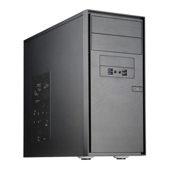
Page 10: Chassis Features
Desktop 5130DB-IL User's Manual 1.3 Chassis Features Front Features The DS3A-261B is a compact Mini Tower chassis. The front of the chassis includes a power on/off push-button and several LEDs as described below. Figure 1-1. Chassis Front View Front Chassis Features... -
Page 11: Rear Features
Chapter 1: Introduction Rear Features Various input/output ports can be accessed at the rear of the chassis. Figure 1-2. Rear I/O Ports Rear I/O Ports Description Description Description PS2 Keyboard/Mouse Port USB4 Port (USB 3.0) Surround Out USB0 Port (USB 2.0) USB5 Port (USB 3.0) SPDIF Out USB1 Port (USB 2.0) -
Page 12: Displayport
Desktop 5130DB-IL User's Manual DisplayPort DisplayPort, develped by the VESA consortium, delivers digital display and fast refresh rates. It can connect to virtually any display device using a DisplayPort adapter for devices such as VGA, DVI or HDMI. HDMI Port The HDMI (High-Definition Multimedia Interface) port is used to display both high definition video and digital sound through an HDMI-capable display, using the same (HDMI) cable. -
Page 13: Motherboard Layout
Chapter 1: Introduction 1.4 Motherboard Layout Jumper, connector and LED locations are shown below with brief descriptions on the following page. Detailed descriptions are found in Chapter 3. JPUSB1 JPW2 CPU_FAN1 J9701 J9702 JI2C2 JI2C1 SYS_FAN2 CPU SLOT3 PCI-E 3.0 X16 JSPDIF_OUT C7B250-CB-ML PCH SLOT2 PCI-E 3.0 X4... -
Page 14: Quick Reference Table
Desktop 5130DB-IL User's Manual Quick Reference Table Jumper Description Default Setting JBR1 BIOS Recovery Pins 1-2: (Normal) JBT1 Clear CMOS Short pads to clear CMOS JCMOS Clear CMOS Pins 1-2: (Normal) JI2C1/JI2C2 SMB to PCI-E Slots Enable/Disable On: (Enabled) JPME2 Intel®... -
Page 15: System Block Diagram
Chapter 1: Introduction System Block Diagram SVID IMVP8 IMVP8 PCIe x16 SLOT #6 PCIe3.0_x8 PCIe3.0_x16 INTEL LGA1151 8.0GT/s 8.0GT/s 2400/2133/1866/1600MHz PCIe x8(in x16) SLOT #6 DDI1 (Socket-H4) HDMI DIMMA0 DDI 1 DDR4 (CHA) DIMMA1 DDI2 Display Port DDI 2 DDR4 (CHB) DDI3 DIMMB0 DDI 3... -
Page 16: Chapter 2 Maintenance And Component Installation
Desktop 5130DB-IL User's Manual Chapter 2 Maintenance and Component Installation This chapter provides instructions on installing and replacing main system components. To prevent compatibility issues, only use components that match the specifications and/or part numbers given. Installation or replacement of most components requires that power first be removed from the system. -
Page 17: Installing Hard Drives
Chapter 2 Maintenance and Component Installation Release Figure 2-1. Removing the Chassis Cover 2.3 Installing Hard Drives Removing and Installing Hard Drives 1. Power down the system and remove the power cord from the rear of the power supply as described in Section 2.1 and remove the chassis cover as described in Section 2.2. 2. - Page 18 Desktop 5130DB-IL User's Manual Release Figure 2-2. Removing a Hard Drive Carrier from the Chassis 5. If a hard drive or dummy drive is present, simultaneiously pull both sides of the hard drive carrier open and lift the drive out.
- Page 19 Chapter 2 Maintenance and Component Installation 7. Insert the hard drive carrier into the hard drive bay, sliding it towards the back of the the hard drive bay until it clicks into a locked position. 8. Connect the cables to the hard drives, plug the power cord into the rear of the power supply, replace the chassis cover and power up the system.
-
Page 20: Removing And Installing The Front Bezel
Desktop 5130DB-IL User's Manual 2.4 Removing and Installing the Front Bezel Front Bezel Removal 1. Power down the system and remove the power cord from the rear of the power supply as described in Section 2.1 and remove the chassis cover as described in Section 2.2. -
Page 21: Installing A Peripheral Device
Chapter 2 Maintenance and Component Installation 2.5 Installing a Peripheral Device The DS3A-261B chassis has two bays for optional peripheral devices, such as a DVD drive. Installing a Peripheral Device 1. Power down the system and remove the power cord from the rear of the power supply as described in Section 2.1 and remove the chassis cover as described in Section 2.2. -
Page 22: Installing Expansion Cards
Desktop 5130DB-IL User's Manual 2.6 Installing Expansion Cards The DS3A-261B chassis includes four slots for expansion cards. Installing Expansion Cards 1. Power down the system and remove the power cord from the rear of the power supply as described in Section 2.1 and remove the chassis cover as described in Section 2.2. -
Page 23: Installing The System Fan
Chapter 2 Maintenance and Component Installation 2.7 Installing the System Fan The DS3A-261B includes a rear system fan that provides cooling for the chassis. In the event that it becomes necessary to replace the fan, use the following instructions. Caution: This is not a hot-swap fan. Four screws are required to install the system fan. Installing the System Fan 1. -
Page 24: Installing A Power Supply
Desktop 5130DB-IL User's Manual 2.7 Installing a Power Supply The DS3A-261B has a single 260 Watt power supply, which is not a hot-swap unit..In the event the power module fails or it bcomes necessary to replace the power supply, follow the instructions below. -
Page 25: Installing A Processor And Heatsink
2.8 Installing a Processor and Heatsink Installing the Processor The 5130DB-IL supports a single Intel 6th/7th Gen Core i7/i5/i3, Pentium or Celeron processor in an LGA1151 socket. 1. Press the load lever to release the load plate, which covers the CPU socket, from its locking position. - Page 26 Desktop 5130DB-IL User's Manual 4. Align the CPU key that is the semi-circle cutouts against the socket keys. Once it is aligned, carefully lower the CPU straight down into the socket. (Do not drop the CPU on the socket. Do not move the CPU horizontally or vertically.
-
Page 27: Installing The Heatsink
Chapter 2 Maintenance and Component Installation Installing the Heatsink 1. Locate the CPU fan connector on the motherboard. 2. Position the heatsink so that the heatsink fan wires are closest to the CPU fan connector and do not interfere with other components. -
Page 28: Removing The Heatsink
Desktop 5130DB-IL User's Manual 7. Align the four heatsink fasteners with the mounting holes on the motherboard. Gently push the pairs of diagonal fasteners (#1 & #2, and #3 & #4) into the mounting holes until you hear a click. -
Page 29: Installing Memory
Memory Support The motherboard supports up to 64 GB of unbuffered, non-ECC DDR4-2400 memory in four DIMM slots. Two DIMMs should be installed at a time. Check the Supermicro website for a list of validated memory. Caution: Exercise extreme care when installing or removing DIMM modules to prevent damage. -
Page 30: Memory Population Guidelines
Desktop 5130DB-IL User's Manual Note: Be sure to use memory modules of the same type, same speed, same frequency on the same motherboard. Mixing of memory modules of different types and speeds is not allowed. Due to memory allocation to system devices, the amount of memory that remains available for operational use will be reduced when 4 GB of RAM is used. -
Page 31: Motherboard Battery
Chapter 2 Maintenance and Component Installation 2.10 Motherboard Battery The motherboard uses non-volatile memory to retain system information when system power is removed. This memory is powered by a lithium battery residing on the motherboard. LITHIUM BATTERY LITHIUM BATTERY BATTERY HOLDER BATTERY HOLDER Figure 2-12. -
Page 32: Chapter 3 Motherboard Connections
Desktop 5130DB-IL User's Manual Chapter 3 Motherboard Connections This section describes the connections on the C7B250-CB-ML motherboard and provides pinout definitions. Note that depending on how the system is configured, not all connections are required. The LEDs on the motherboard are also described here A motherboard layout indicating component locations may be found in Chapter 1. -
Page 33: Headers And Connectors
Chapter 3: Motherboard Connections 3.2 Headers and Connectors Fan Headers There are three 4-pin fan headers on the motherboard. Although pin 4 is for PWM control, the fan in the 5130DB-IL does not utilize PWM (Pulse Width Modulation). Fan Header Pin Definitions Pin#... - Page 34 Desktop 5130DB-IL User's Manual TPM Header The JTPM1 header is used to connect a Trusted Platform Module (TPM), which is available from a third-party vendor. A TPM is a security device that supports encryption and authentication in hard drives. It enables the motherboard to deny access if the TPM associated with the hard drive is not installed in the system.
- Page 35 Chapter 3: Motherboard Connections SATA Ports The motherboard has six SATA 3.0 ports (I-SATA0-5) that are supported by the Intel PCH. M.2 Slot M.2 is formerly known as Next Generation Form Factor (NGFF). The M.2 slot (designated PCIE M.2 Connector 1) is designed for internal mounting devices. The C7B250-CB-ML motherboard deploys the 2242/2280 M-key dedicated for SSD devices with the ulitmate performance capability in a PCI Express 3.0 x4 interface for native PCI-E SSD support.
-
Page 36: Control Panel Header
Desktop 5130DB-IL User's Manual Control Panel Header JF1 contains header pins for various control panel connections. See the figure below for the pin locations and definitions of the control panel buttons and LED indicators. All JF1 wires have been bundled into a single cable to simplify this connection. Make sure the red wire plugs into pin 1 as marked on the motherboard. - Page 37 Chapter 3: Motherboard Connections Fan Fail Connect an LED cable to Fan Fail connections on pins 7 and 8 of JF1 to provide warnings for chassis overheat/fan failure. Fan Fail/Overheat Fan Fail LED Indicator Status Pin Definitions (JF1) Pin# Definition Pins Definition Normal...
-
Page 38: Rear I/O Ports
Desktop 5130DB-IL User's Manual 3.3 Rear I/O Ports See Section 1.3 for an illustration showing the rear I/O port locations. DisplayPort DisplayPort, develped by the VESA consortium, delivers digital display and fast refresh rates. It can connect to virtually any display device using a DisplayPort adapter for devices such as VGA, DVI or HDMI. -
Page 39: Usb (Universal Serial Bus) Ports
Chapter 3: Motherboard Connections USB (Universal Serial Bus) Ports Four USB 3.0 ports (USB4, 5, 6 ,7) and two USB 2.0 ports (USB0, 1) are located on the I/O back panel. In addition, one USB 3.0 header for two ports (USB8/9) and one USB 2.0 header for two ports: (USB2/3) are located on the motherboard to provide front chassis access using USB cables (not included). -
Page 40: Jumpers
Desktop 5130DB-IL User's Manual 3.4 Jumpers Explanation of Jumpers To modify the operation of the motherboard, jumpers are used to choose between optional settings. Jumpers create shorts between two pins to change the function associated with it. Pin 1 is identified with a square solder pad on the printed circuit board. See the motherboard layout page for jumper locations. - Page 41 Chapter 3: Motherboard Connections SMBus to PCI Slots Jumpers JI C1 and JI C2 allow you to connect the System Management Bus (I C) to the PCI-E/PCI slots. (JI C1 controls the clock and JI C2 controls the data). Both jumpers must be set to the same setting.
-
Page 42: Led Indicators
Desktop 5130DB-IL User's Manual 3.5 LED Indicators LAN Port LEDs The Ethernet port has two LEDs. The Activity LED indicates network activity when flashing. The Link LED may be green, amber or off to indicate the speed of the connection. -
Page 43: Chapter 4 Software
This section describes the installation of drivers and management programs for the system. 4.1 Driver Installation The Supermicro FTP site contains drivers and utilities for your system at ftp://ftp.supermicro. com. Some of these must be installed, such as the chipset driver. -
Page 44: Superdoctor ® 5
4.2 SuperDoctor ® The Supermicro SuperDoctor 5 is a program that functions in a command-line or web-based interface for Windows and Linux operating systems. The program monitors such system health information as CPU temperature, system voltages, system power consumption, fan speed, and provides alerts via email or Simple Network Management Protocol (SNMP). -
Page 45: Chapter 5 Bios
Chapter 5: BIOS Chapter 5 BIOS 5.1 Introduction This chapter describes the AMI BIOS setup utility for the C7B250-CB-ML and provides the instructions on navigating the setup screens. The BIOS is stored in a Flash EEPROM and can be updated. Note: Due to periodic changes to the BIOS, some settings may have been added or deleted since this manual was published. -
Page 46: System Information
Desktop 5130DB-IL User's Manual How To Change the Configuration Data The configuration data that determines the system parameters may be changed by entering the AMI BIOS GUI Setup utility. This Setup utility can be accessed by pressing <Del> at the appropriate time during system boot. -
Page 47: Cpu
Chapter 5: BIOS System Date Click on the date to open the setup fields. This item sets and displays the system date. Click the up and down arrows to adjust the date. System Time Click on the time to open the setup fields. This item sets and displays the system time. Click the up and down arrows to adjust the system time. - Page 48 Desktop 5130DB-IL User's Manual • GT Info - this item shows the processor's GT information. • IGFX VBIOS Version - this item shows the Integrated Graphics VBIOS version. • IGFX GOP Version - this item shows the Integrated Graphics VOP version.
- Page 49 Chapter 5: BIOS • L4 Cache - indicates if Level 4 cache is supported. • VMX - indicates if VMX is supported. • SMX/TXT - indicates if SMX/TXT is supported. SW Guard Extension (SGX) Select Enabled to activate the Software Guard Extensions (SGX). The options are Enabled, Disabled, and Software Controlled.
- Page 50 Desktop 5130DB-IL User's Manual Hyper-Threading Select Enabled to support Intel Hyper-threading Technology to enhance CPU performance. The options are Enabled and Disabled. BIST Select Enabled to activate the Built-In Self Test (BIST) on reset. The options are Enabled and Disabled.
- Page 51 Chapter 5: BIOS FCLK Frequency for Early Power On Select the FCLK frequency for early power on. The options are Normal (800MHz), 1GHz and 400MHz. Power and Performance CPU - Power Management Control Boot Performance Mode This option enables the selection of the default CPU performance during system boot. The options are Max Non-Turbo Performance, Max Battery, and Turbo Performance.
- Page 52 Desktop 5130DB-IL User's Manual Platform PL2 Enable This option disables or enables the Platform Power Limit 2 programming. If this option is enabled, it activates the PL1 value to be used by the processor to limit the average power of the given time window. The options are Disabled and Enabled.
- Page 53 Chapter 5: BIOS Package C State Limit Select Auto for the AMI BIOS to automatically set the limit on the C-State package register. The options are C0, C2, C3, C6, C7, C7s, and Auto. Package C State Workaround Enable this feature to fix old HDDs that have problems entering the Package C State. The options are Disabled and Enabled.
-
Page 54: Memory
Desktop 5130DB-IL User's Manual 5.4 Memory The following information is displayed in this section: • Memory RC Version • Memory Frequency • Memory Timings (tCL-tRCD-tRP-tRAS) • DIMM#A1 ~ DIMM#B2 Maximum Memory Frequency This option selects the type/speed of the installed memory. The options are 1333, 1600, 1867, 2133, 2400, 2667, 2933, and 3200. -
Page 55: Advanced
Chapter 5: BIOS Channel A DIMM Control This feature enables or disables the selected Channel A DIMM slot(s). The settings are Enable Both DIMMs, Disable DIMM0, Disable DIMM1 and Disable Both DIMMs. Channel B DIMM Control This feature enables or disables the selected Channel B DIMM slot(s). The settings are Enable Both DIMMs, Disable DIMM0, Disable DIMM1 and Disable Both DIMMs. - Page 56 Desktop 5130DB-IL User's Manual Quiet Boot Use this feature to select the screen display between the POST messages and the OEM logo upon bootup. Uncheck the box to display the POST messages. Check the box to display the OEM logo instead of the normal POST messages.
-
Page 57: Nct6792D Super Io Configuration
Chapter 5: BIOS NCT6792D Super IO Configuration SuperIO Chip NCT6792D Serial Port 1 Configuration Serial Port This item will Enable or Disable Serial Port 1 (COM1). Place a tick mark on the box to enable Serial Port 1. The default is Enabled. Device Settings This item displays the current IRQ setting for Serial Port 1 (COM1). -
Page 58: Serial Port Console Redirection
Desktop 5130DB-IL User's Manual Serial Port Console Redirection COM 1 Console Redirection Select Enabled to enable COM Port 1 Console Redirection, which will allow a client machine to be connected to a host machine at a remote site for networking. The options are Disabled (unchecked) and Enabled (checked). - Page 59 Chapter 5: BIOS Bits per second Use this item to set the transmission speed for a serial port used in Console Redirection. Make sure that the same speed is used in the host computer and the client computer. A lower transmission speed may be required for long and busy lines.
-
Page 60: Legacy Console Redirection
Desktop 5130DB-IL User's Manual Putty KeyPad This feature selects Function Keys and KeyPad settings for Putty, which is a terminal emulator designed for the Windows OS. The options are VT100, LINUX, XTERMR6, SCO, ESCN, and VT400. Redirection After BIOS POST Use this feature to enable or disable legacy Console Redirection after BIOS POST. -
Page 61: System Agent (Sa) Configuration
Chapter 5: BIOS to map Unicode characters into one or more bytes. The options are ANSI, VT100, VT100+, and VT-UTF8. Bits per second This item sets the transmission speed for a serial port used in Console Redirection. Make sure that the same speed is used in both host computer and the client computer. A lower transmission speed may be required for long and busy lines. -
Page 62: Peg Port Configuration
Desktop 5130DB-IL User's Manual The following will be displayed: • SA PCIe Code Version • VT-d Capability PEG Port Configuration PEG 0:1:0 Enable Root Port Select Enable to activate the Root Port. The options are Disabled, Enabled, and Auto. Max Link Speed Select Auto, Gen1, Gen2, or Gen3 to set the PEG Max Link Speed. -
Page 63: Peg 0:1:2
Chapter 5: BIOS PEG1 Physical Slot Number This option sets the physical slot number attached to this port. The number has be globally unique within the chassis. Valid range is from 0-8191. PEG 0:1:2 Enable Root Port Select Enable to activate the Root Port. The options are Disabled, Enabled, and Auto. Max Link Speed Select Auto, Gen1, Gen2, or Gen3 to set the PEG Max Link Speed. - Page 64 Desktop 5130DB-IL User's Manual Graphics Turbo IMON Current Use this feature to set the limit on the current voltage regulator. Valid range is 14-31. Default is 31. Skip Scanning of External Gfx Card Use this feature to scan for External Gfx Card on PEG and PCH PCIE Ports. If this feature is enabled, the system will not scan for a new card.
- Page 65 Chapter 5: BIOS DVMT Total Gfx Mem Use this feature to set the total memory size to be used by internal graphics devices based on the DVMT 5.0 platform. The options are 128MB, 256MB, and MAX. Gfx Low Power Mode Select Enabled to use the low power mode for internal graphics devices installed in a small form factor (SFF) computer.
-
Page 66: Pch-Io Configuration
Desktop 5130DB-IL User's Manual PCH-IO Configuration DMI Link ASPM Control Use this feature to set the ASPM (Active State Power Management) state on the SA (System Agent) side of the DMI Link. The options are Enabled and Disabled. PCIe Root Ports ASPM Use this feature to set the Active State Power Management (ASPM) to power manage the PCIe link during the various L states. -
Page 67: Sata And Rst Configuration
Chapter 5: BIOS Pcie PII SSC Use this feature to set the PCIE PII SSC percentage. Select Auto to keep the hardware default with no BIOS override. The range is from 0.0% to 2.0%. SATA and RST Configuration SATA Controllers Select Disabled to disable the onboard SATA Controllers. - Page 68 Desktop 5130DB-IL User's Manual Serial ATA Port This item displays the detected SATA drive, if any. Hot Plug This feature designates the port specified for hot plugging. Set this item to Enabled for hot- plugging support, which will allow the user to replace a SATA disk drive without shutting down the system.
-
Page 69: Pch Fw Configuration
Chapter 5: BIOS PCH FW Configuration The following information is shown for the PCH Firmware. • ME Firmware Version • ME Firmware Mode • ME Firmware SKU • ME FW Image Re-Flash This item will update the PCH Firmware from an image in a USB flash drive attached to a USB port. -
Page 70: Usb Configuration
Desktop 5130DB-IL User's Manual USB Configuration The following information is shown for USB Configuration. • USB Module Version • USB Controllers • USB Devices Legacy USB Support Select Enabled to support legacy USB devices. Select Auto to disable legacy support when legacy USB devices are not present. -
Page 71: Pcie/Pci/Pnp Configuration
Chapter 5: BIOS Install Windows 7 USB Support Enable this feature to use the USB keyboard and mouse during the Windows 7 installation, since the native XHCI driver support is unavailable. Use a SATA optical drive such as a USB drive. -
Page 72: Pcie/Pci/Pnp Configuration
Desktop 5130DB-IL User's Manual PCIe/PCI/PnP Configuration PCH SLOT1 PCI-E 3.0 X1 OPROM, PCH SLOT2 PCI-E 3.0 X4 OPROM CPU SLOT3 PCI-E 3.0 X16 OPROM Select Disabled to deactivate the selected slot, Legacy to activate the slot in legacy mode and EFI to activate the slot in EFI mode. The options are Disabled, Legacy, and EFI. -
Page 73: Security
Chapter 5: BIOS Security This menu allows the user to configure the following security settings for the system. • If the ONLY the Administrator's password is defined - this controls access to the BIOS setup only. • If the ONLY the User's password is defined - this password will need to be entered upon each system boot, and will also have Administrator rights in the setup. -
Page 74: Secure Boot
Desktop 5130DB-IL User's Manual Secure Boot The following items will be displayed: • System Mode • Secure Boot • Vendor Keys Attempt Secure Boot Select Enabled for Secure Boot flow control. This feature is available when the platform key (PK) is pre-registered, the platform operates in the user mode, and CSM is disabled in the Setup utility. -
Page 75: Key Management
Chapter 5: BIOS Key Management Provision Factory Default Keys Allows provisioning the factory default secure boot keys when system is in setup mode. The options are Disabled and Enabled. (if Secure Boot Mode is set to 'Custom') Key Management allows experienced users to modify Secure Boot Variables. Install Factory Default Keys This option forces the system to install the factory default keys. - Page 76 Desktop 5130DB-IL User's Manual Platform Key (PK) This item uploads and installs a secure Platform Key. You may insert a factory default key or load from a file. The file formats accepted are: 1) Public Key Certificate a. EFI Signature List b.
- Page 77 Chapter 5: BIOS Delete Forbidden Signature This item deletes a previously installed Forbidden Signature. Forbidden Signatures This item uploads and installs a Forbidden Signature . You may insert a factory default key or load from a file. The file formats accepted are: 1) Public Key Certificate a.
-
Page 78: Thermal And Fan
Desktop 5130DB-IL User's Manual OsRecovery Signatures This item uploads and installs an OSRecovery Signature . You may insert a factory default key or load from a file. The file formats accepted are: 1) Public Key Certificate a. EFI Signature List b. - Page 79 Chapter 5: BIOS • Peripheral Temperature - displays the detected peripheral device temperature. • PCH Temperature - indicates the detected PCH chip temperature. System Health The following items will be displayed (Voltage): • VCPU • • VCCSA • 5VCC • VDIMM •...
-
Page 80: Save And Exit
Desktop 5130DB-IL User's Manual systems with normal hardware configurations. Select "Quiet" to optimize for minimal fan noise and Custom to enter user-specific settings. The options are Quiet, Stable, Full Speed and Customize. When "Customize" is selected above, the settings for CPU_FAN1 Control, SYS FAN1/FAN2 Control will appear and can be configured. - Page 81 Chapter 5: BIOS NETWORK Drive BBS Priorities Use this feature to specify the Boot Device Priority sequence from available Network Drives. The options are IBA CL Slot 00FE v0110 and Disable. Boot Override Saves the specified boot override and resets the system, i.e., IBA CL Slot 00FE v0110. Select OK to activate, otherwise, click Cancel.
-
Page 82: Bios Update
Desktop 5130DB-IL User's Manual 5.8 BIOS Update The following items will be displayed: • BIOS Version • BIOS Tag • Date • Time Start Update Use this utility to prepare BIOS Update with ME. 1. Click "Start Update" enter the SuperFlash utility. - Page 83 Chapter 5: BIOS 6. Select "Start Flash" to flash the BIOS. A pop-up message will appear to show the progress of the BIOS flash. 7. If the flash is successful, a pop-up message will indicate the result. Select "OK" to complete the BIOS flash and to reboot the system.
-
Page 84: Appendix A Bios Codes
SuperServer 5130DB-IL User's Manual Appendix A BIOS Codes A.1 BIOS Error POST (Beep) Codes During the POST (Power-On Self-Test) routines, which are performed each time the system is powered on, errors may occur. Non-fatal errors are those which, in most cases, allow the system to continue the boot-up process. -
Page 85: Appendix B Standardized Warning Statements For Ac Systems
Supermicro's Technical Support department for assistance. Only certified technicians should attempt to install or configure components. Read this appendix in its entirety before installing or configuring components in the Supermicro chassis. These warnings may also be found on our website at http://www.supermicro.com/about/... - Page 86 Appendix B: Standardized Warning Statements Warnung WICHTIGE SICHERHEITSHINWEISE Dieses Warnsymbol bedeutet Gefahr. Sie befinden sich in einer Situation, die zu Verletzungen führen kann. Machen Sie sich vor der Arbeit mit Geräten mit den Gefahren elektrischer Schaltungen und den üblichen Verfahren zur Vorbeugung vor Unfällen vertraut. Suchen Sie mit der am Ende jeder Warnung angegebenen Anweisungsnummer nach der jeweiligen Übersetzung in den übersetzten Sicherheitshinweisen, die zusammen mit diesem Gerät ausgeliefert wurden.
- Page 87 Desktop 5130DB-IL User's Manual جسذٌة اصابة ًتتسبب ف حالة ٌوكي أى ًاًك ف خطز ًٌٌع هذا الزهز !تحذٌز الذوائز بالوخاطز الٌاجوة عي ي على علن ، ك هعذات تعول على أي قبل أى الكهزبائٍة حىادث أي وقىع وٌع ل الىقائٍة...
- Page 88 Appendix B: Standardized Warning Statements Warnung Vor dem Anschließen des Systems an die Stromquelle die Installationsanweisungen lesen. ¡Advertencia! Lea las instrucciones de instalación antes de conectar el sistema a la red de alimentación. Attention Avant de brancher le système sur la source d'alimentation, consulter les directives d'installation. מתח...
- Page 89 Desktop 5130DB-IL User's Manual Warnung Dieses Produkt ist darauf angewiesen, dass im Gebäude ein Kurzschluss- bzw. Überstromschutz installiert ist. Stellen Sie sicher, dass der Nennwert der Schutzvorrichtung nicht mehr als: 250 V, 20 A beträgt. ¡Advertencia! Este equipo utiliza el sistema de protección contra cortocircuitos (o sobrecorrientes) del edificio.
- Page 90 Appendix B: Standardized Warning Statements Power Disconnection Warning Warning! The system must be disconnected from all sources of power and the power cord removed from the power supply module(s) before accessing the chassis interior to install or remove system components. 電源切断の警告...
- Page 91 Desktop 5130DB-IL User's Manual امداد وحدة من سهك انكهرباء وإزانت انطاقت مصادر من جميع اننظاو يجب فصم قبم انطاقت الجهاز مكىناث نتثبيج أو إزانت ههيكم ن انمناطق انداخهيت انىصىل إنى 경고! 시스템에 부품들을 장착하거나 제거하기 위해서는 섀시 내부에 접근하기 전에 반드시 전원...
- Page 92 Appendix B: Standardized Warning Statements Attention Il est vivement recommandé de confier l'installation, le remplacement et la maintenance de ces équipements à des personnels qualifiés et expérimentés. !אזהרה .הציוד או לתת שירות עבור הציוד אי להתקין, להחליף את צוות מוסמך בלבד רש هذا...
- Page 93 Desktop 5130DB-IL User's Manual Warnung Diese Einheit ist zur Installation in Bereichen mit beschränktem Zutritt vorgesehen. Der Zutritt zu derartigen Bereichen ist nur mit einem Spezialwerkzeug, Schloss und Schlüssel oder einer sonstigen Sicherheitsvorkehrung möglich. ¡Advertencia! Esta unidad ha sido diseñada para instalación en áreas de acceso restringido. Sólo puede obtenerse acceso a una de estas áreas mediante la utilización de una herramienta especial,...
- Page 94 Appendix B: Standardized Warning Statements Battery Handling Warning! There is the danger of explosion if the battery is replaced incorrectly. Replace the battery only with the same or equivalent type recommended by the manufacturer. Dispose of used batteries according to the manufacturer's instructions 電池の取り扱い...
- Page 95 Desktop 5130DB-IL User's Manual فعليل بطريقة غير صحيحة البطارية انفجار في حالة اسحبذال من هناك خطر اسحبذال البطارية به الشرمة المصنعة أوصث مما أو ما يعادلها بنفس النىع فقط حعليمات الشرمة الصانعة المسحعملة وفقا ل جخلص من البطاريات 경고! 배터리가 올바르게 교체되지 않으면 폭발의 위험이 있습니다. 기존 배터리와 동일하거나 제...
- Page 96 Appendix B: Standardized Warning Statements ¡Advertencia! Puede que esta unidad tenga más de una conexión para fuentes de alimentación. Para cortar por completo el suministro de energía, deben desconectarse todas las conexiones. Attention Cette unité peut avoir plus d'une connexion d'alimentation. Pour supprimer toute tension et tout courant électrique de l'unité, toutes les connexions d'alimentation doivent être débranchées.
- Page 97 Desktop 5130DB-IL User's Manual Backplane Voltage Warning! Hazardous voltage or energy is present on the backplane when the system is operating. Use caution when servicing. バックプレーンの電圧 システムの稼働中は危険な電圧または電力が、 バックプレーン上にかかっています。 修理する際には注意く ださい。 警告 当系统正在进行时,背板上有很危险的电压或能量,进行维修时务必小心。 警告 當系統正在進行時,背板上有危險的電壓或能量,進行維修時務必小心。 Warnung Wenn das System in Betrieb ist, treten auf der Rückwandplatine gefährliche Spannungen oder Energien auf.
- Page 98 Appendix B: Standardized Warning Statements اللىحة أوالطاقة المىجىدة على التيار الكهزبائي مه خطز هناك هذا الجهاس خدمة كه حذرا عند يعمل النظام عندما يكىن 경고! 시스템이 동작 중일 때 후면판 (Backplane)에는 위험한 전압이나 에너지가 발생 합니다. 서비스 작업 시 주의하십시오. Waarschuwing Een gevaarlijke spanning of energie is aanwezig op de backplane wanneer het systeem in gebruik is.
- Page 99 Desktop 5130DB-IL User's Manual תיאום חוקי החשמל הארצי !אזהרה הציוד חייבת להיות תואמת לחוקי החשמל המקומיים והארציים התקנת المتعلقة المحلية والىطىية قىاويه يجب أن يمتثل لل الكهربائية تركيب المعدات بالكهرباء 경고! 현 지역 및 국가의 전기 규정에 따라 장비를 설치해야 합니다.
- Page 100 Appendix B: Standardized Warning Statements Attention La mise au rebut ou le recyclage de ce produit sont généralement soumis à des lois et/ou directives de respect de l'environnement. Renseignez-vous auprès de l'organisme compétent. סילוק המוצר !אזהרה .חוקי המדינה סילוק סופי של מוצר זה חייב להיות בהתאם להנחיות ו القىانين...
- Page 101 Desktop 5130DB-IL User's Manual Warnung Gefährlich Bewegende Teile. Von den bewegenden Lüfterblätter fern halten. Die Lüfter drehen sich u. U. noch, wenn die Lüfterbaugruppe aus dem Chassis genommen wird. Halten Sie Finger, Schraubendreher und andere Gegenstände von den Öffnungen des Lüftergehäuses entfernt.
- Page 102 Electrical Appliance and Material Safety Law prohibits the use of UL or CSA -certified cables (that have UL/CSA shown on the code) for any other electrical devices than products designated by Supermicro only. 電源コードとACアダプター...
- Page 103 .قيرح وأ لطع يف ببستي دق ىرخأ تالوحمو تالباك يأ مادختسا .ميلسلا سباقلاو لصوملا مجح لبق نم ةدمتعملا تالباكلا مادختسا تادعملاو ةيئابرهكلا ةزهجألل ةمالسلا نوناق رظحيUL وأCSA ( ةمالع لمحت يتلاوUL/CSA) لبق نم ةددحملاو ةينعملا تاجتنملا ريغ ىرخأ تادعم يأ عمSupermicro.
- Page 104 사항을 준수하여 제공되거나 지정된 연결 혹은 구매 케이블, 전원 케이블 및 AC 어댑터를 사용하십시오. 다른 케이블이나 어댑터를 사용하면 오작동이나 화재가 발생할 수 있습니다. 전기 용품 안전법은 UL 또는 CSA 인증 케이블 (코드에 UL / CSA가 표시된 케이블)을 Supermicro 가 지정한 제품 이외의 전기 장치에 사용하는 것을 금지합니다. Stroomkabel en AC-Adapter...
-
Page 105: Appendix C System Specifications
Appendix C: System Specifications Appendix C System Specifications Processors Single Intel 6th/7th Gen Core i7/i5/i3, Pentium or Celeron in an LGA1151 type socket Note: Please refer to the motherboard specifications pages on our website for updates to supported processors. Chipset Intel B250 Express chipset BIOS 128 Mb AMI®... - Page 106 SuperServer 5130DB-IL User's Manual Regulatory Compliance Electromagnetic Emissions: FCC Class B, EN 55022 Class B, EN 61000-3-2/3-3, CISPR 22 Class B Electromagnetic Immunity: EN 55024/CISPR 24, (EN 61000-4-2, EN 61000-4-3, EN 61000-4-4, EN 61000-4-5, EN 61000-4-6, EN 61000-4-8, EN 61000-4-11)
-
Page 107: Appendix D Uefi Bios Recovery Instructions
Warning: Do not upgrade the BIOS unless your system has a BIOS-related issue. Flashing the wrong BIOS can cause irreparable damage to the system. In no event shall Supermicro be liable for direct, indirect, special, incidental, or consequential damages arising from a BIOS update. - Page 108 SuperServer 5130DB-IL User's Manual 2. Insert the USB device that contains the new BIOS image ("SUPER.ROM") into any available USB port. Be sure the file is saved in the very top (root) folder. 3. Set JBR1 on the motherboard to recovery mode and power on the system. If the screen...
- Page 109 Appendix D: UEFI BIOS Recovery 4. After locating the new BIOS binary image, the system will enter the BIOS Recovery menu as shown below. Note: At this point, you may decide if you want to start the BIOS Recovery. If you decide to proceed with BIOS Recovery, follow the procedures below.
Need help?
Do you have a question about the 5130DB-IL and is the answer not in the manual?
Questions and answers