Table of Contents
Advertisement
Quick Links
Advertisement
Table of Contents

Subscribe to Our Youtube Channel
Related Manuals for Supermicro SuperWorkstation 7037A-IL


Summary of Contents for Supermicro SuperWorkstation 7037A-IL
- Page 1 UPER ® uper orkstation 7037A-IL USER’S MANUAL...
- Page 2 This product, including software and docu- mentation, is the property of Supermicro and/or its licensors, and is supplied only under a license. Any use or reproduction of this product is not allowed, except as expressly permitted by the terms of said license.
-
Page 3: About This Manual
About This Manual This manual is written for professional system integrators and PC technicians. It provides information for the installation and use of the SuperWorkstation 7037A-IL. Installation and maintenance should be performed by experienced technicians only. The SuperWorkstation 7037A-IL is a high-end system based on the SC732D4F- 500B tower/4U rackmount chassis and the X9DAL-i serverboard. - Page 4 uper orkstation 7037A-IL User's Manual Chapter 5: Advanced Serverboard Setup Chapter 5 provides detailed information on the X9DAL-i serverboard, including the locations and functions of connections, headers and jumpers. Refer to this chapter when adding or removing processors or main memory and when reconfi guring the serverboard.
- Page 5 Preface Notes...
-
Page 6: Table Of Contents
Chassis Features .................... 1-3 System Power ....................1-3 SAS Subsystem ....................1-3 Front Control Panel ..................1-3 Cooling System ....................1-3 Contacting Supermicro ..................1-5 Chapter 2 Installation Overview ......................2-1 Unpacking the System ..................2-1 Accessing the Inside of the System..............2-2 Chapter 3 System Interface Overview ...................... - Page 7 Table of Contents Chapter 5 Advanced Serverboard Setup Handling the Serverboard ................5-1 Precautions ..................... 5-1 Unpacking ....................... 5-1 Connecting Cables ..................5-2 Connecting Data Cables ................. 5-2 Connecting Power Cables ................5-2 Connecting the Control Panel ................. 5-2 I/O Ports ......................5-3 Processor and Heatsink Installation..............
- Page 8 uper orkstation 7037A-IL User's Manual Starting BIOS Setup Utility ................7-1 How To Change the Confi guration Data ............7-2 Starting the Setup Utility ................. 7-2 Main Setup ...................... 7-2 Advanced Setup Confi gurations..............7-4 Event Logs ....................7-24 Boot ....................... 7-26 Security ......................
-
Page 9: Chapter 1 Introduction
SC732D4F-500B tower/4U chassis and the X9DAL-i dual Intel® Xeon® processor serverboard. Please refer to our web site for information on operating systems that have been certifi ed for use with the SuperWorkstation 7037A-IL (www.supermicro. com). In addition to the serverboard and chassis, various hardware components have been included with the SuperWorkstation 7037A-IL, as listed below: •... -
Page 10: Serverboard Features
7037A-IL User's Manual Serverboard Features At the heart of the SuperWorkstation 7037A-IL lies the X9DAL-i, a dual processor serverboard based on the Intel® C602 chipset. Below are the main features of the X9DAL-i. (See Figure 1-1 for a block diagram of the chipset). -
Page 11: Chassis Features
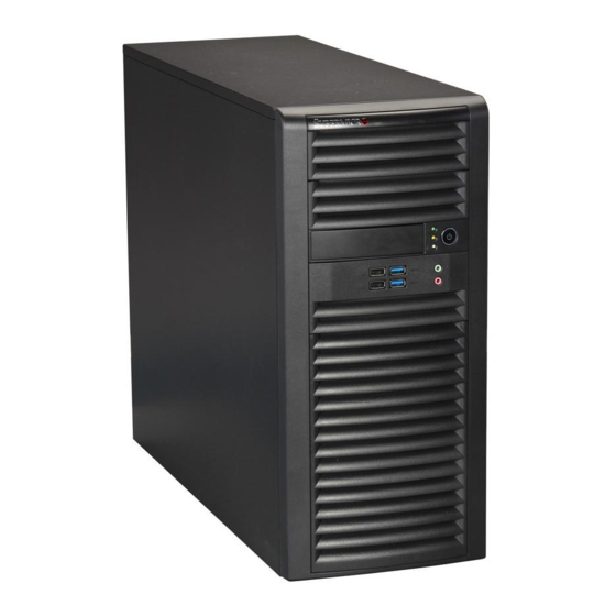
The SC732D4F-500B chassis was designed to support eight SATA hard drives. Front Control Panel The control panel on the SuperWorkstation 7037A-IL includes system monitoring LEDs, a main power button and a system reset button. In addition, two IEEE 1394a ports, two USB 2.0 ports, two USB 3.0 ports, one audio port and one microphone port are included on the control panel. -
Page 12: System Block Diagram
uper orkstation 7037A-IL User's Manual Figure 1-1. Intel C602 Chipset: System Block Diagram Note: This is a general block diagram. Please see Chapter 5 for details. #1-3 #0-3 #1-2 #0-2 #1-1 #0-1 CPU0 CPU1 DDR3 DDR3 #3A/B/C/D #1A/B #3A/B #3C/D PCI-E X8 G3 SLOT 3 SLOT 5 PCI-E X4 G3... -
Page 13: Contacting Supermicro
Super Micro Computer, Inc. 980 Rock Ave. San Jose, CA 95131 U.S.A. Tel: +1 (408) 503-8000 Fax: +1 (408) 503-8008 Email: marketing@supermicro.com (General Information) support@supermicro.com (Technical Support) Web Site: www.supermicro.com Europe Address: Super Micro Computer B.V. Het Sterrenbeeld 28, 5215 ML... - Page 14 uper orkstation 7037A-IL User's Manual Notes...
-
Page 15: Chapter 2 Installation
Installation Overview This chapter provides a quick setup checklist to get your SuperWorkstation 7037A-IL up and running. Following these steps in the order given should enable you to have the system operational within a minimum amount of time. This quick setup assumes that your system has come to you with the processor and memory preinstalled. -
Page 16: Accessing The Inside Of The System
uper orkstation 7037A-IL User's Manual • To maintain proper cooling, always keep all chassis panels closed and all SATA carriers installed when not being serviced. Accessing the Inside of the System You may need to access the system periodically to perform maintenance or install components such as hard drives. -
Page 17: Chapter 3 System Interface
Chapter 3: System Interface Chapter 3 System Interface Overview The control panel on the 7037A-IL has several LEDs and a power button. There are also two LEDs on each hard drive carrier. These LEDs keep you constantly informed of the overall status of the system and the activity and health of specifi c components. Control Panel Button A single push-button is located on the front of the chassis. -
Page 18: Control Panel Leds
uper orkstation 7037A-IL User's Manual NIC LED HDD LED OH LED Power Button Audio 2x USB 2.0 2x USB 3.0 Control Panel LEDs The control panel located on the front of the SC732 chassis has three LEDs. These LEDs provide you with critical information related to different parts of the system. This section explains what each LED indicates when illuminated and any corrective action you may need to take. -
Page 19: Overheat/Fan Fail
Chapter 3: System Interface Overheat/Fan Fail When this LED fl ashes, it indicates a chassis fan failure. When on continuously it indicates an overheat condition, which may be caused by cables obstructing the airfl ow in the system or the ambient room temperature being too warm. Check the routing of the cables and make sure all fans are present and operating normally. - Page 20 uper orkstation 7037A-IL User's Manual Notes...
-
Page 21: Chapter 4 System Safety
System Safety Electrical Safety Precautions Basic electrical safety precautions should be followed to protect yourself from harm and the SuperWorkstation 7037A-IL from damage: • Be aware of the locations of the power on/off switch on the chassis as well as the room's emergency power-off switch, disconnection switch or electrical outlet. -
Page 22: General Safety Precautions
General Safety Precautions Follow these rules to ensure general safety: • Keep the area around the SuperWorkstation 7037A-IL clean and free of clutter. • The 7037A-IL weighs approximately 39 lbs (17.7 kg.) when fully loaded. When lifting the system, two people at either end should lift slowly with their feet spread out to distribute the weight. -
Page 23: Esd Precautions
Chapter 4: System Safety • After accessing the inside of the system, close the system back up and secure it to the rack unit with the retention screws after ensuring that all connections have been made. ESD Precautions Electrostatic discharge (ESD) is generated by two objects with different electrical charges coming into contact with each other. -
Page 24: Operating Precautions
uper orkstation 7037A-IL User's Manual Operating Precautions Care must be taken to assure that the chassis cover is in place when the system is operating to assure proper cooling. Out of warranty damage to the system can occur if this practice is not strictly followed. Figure 4-1. -
Page 25: Chapter 5 Advanced Serverboard Setup
Chapter 5: Advanced Serverboard Setup Chapter 5 Advanced Serverboard Setup This chapter covers the steps required to connect the data and power cables and install add-on cards. All serverboard jumpers and connections are also described. A layout and quick reference chart are included in this chapter for your reference. Handling the Serverboard Electrostatic discharge (ESD) can damage electronic com ponents. -
Page 26: Connecting Cables
uper orkstation 7037A-IL User's Manual Connecting Cables Now that the serverboard is installed, the next step is to connect the cables to the board. These include the data (ribbon) cables for the peripherals and control panel and the power cables. Connecting Data Cables The cables used to transfer data from the peripheral devices have been carefully routed to prevent them from blocking the fl... -
Page 27: I/O Ports
Chapter 5: Advanced Serverboard Setup Figure 5-1. Control Panel Header Pins Ground Power LED HDD LED NIC1 LED NIC2 LED OH/Fan Fail LED PWR Fail LED Reset Reset Button Ground Power Button Ground I/O Ports The I/O ports are color coded in conformance with the PC 99 specifi cation. See Figure 5-2 below for the colors and locations of the various I/O ports. -
Page 28: Processor And Heatsink Installation
CPU socket cap is in place and none of the socket pins are bent; otherwise, contact your retailer immediately. • Refer to the Supermicro web site for updates on CPU support. Installing an LGA 1356 Processor 1. Press the socket clip to release the load plate covering the CPU socket from its locked position. - Page 29 Chapter 5: Advanced Serverboard Setup 5. Align the CPU key, which is a semi- circle cutout, against the socket key, which is the notch below the gold color dot on the side of the socket. 6. Align pin 1 of the CPU against pin 1 of the CPU socket.
-
Page 30: Installation And Removal Of The Heatsink
uper orkstation 7037A-IL User's Manual Installation and Removal of the Heatsink Installing the Heatsink Heatsinks are optional on the 7037A-IL. 1. Do not apply any thermal grease to the heatsink or the CPU die; the required amount has already been applied. Screw #1 2. -
Page 31: Installing Memory Modules
Chapter 5: Advanced Serverboard Setup Installing Memory Modules Note: Check the Supermicro web site for recommended memory modules. CAUTION Exercise extreme care when installing or removing DIMM modules to prevent any possible damage. Press down the release tabs Installing & Removing DIMMs 1. -
Page 32: Memory Support
uper orkstation 7037A-IL User's Manual Memory Support The X9DAL-i supports up to 192 GB Registered/Unbuffered/Load Reducing ECC/ Non-ECC DDR3-1600/1066/800 MHz memory in six DIMM slots. For the latest memory updates, please refer to our website. For memory to work properly, follow the tables below for the correct order of populat- ing the DIMM slots. -
Page 33: Adding Pci Add-On Cards
Chapter 5: Advanced Serverboard Setup Adding PCI Add-On Cards The 7037A-IL can accommodate standard size add-on cards populated in all slots on the X9DAL-i serverboard. Installing an Add-on Card 1. Begin by removing the PCI slot shield for the slot you wish to populate. 2. -
Page 34: Serverboard Details
uper orkstation 7037A-IL User's Manual Serverboard Details Figure 5-4. X9DAL-i Layout JPL2 COM1 Fan5 USB 3.0 Audio CPU2 Fan3 S I/O CTRL CTRL 7.1 HD Audio LAN 1/2 USB 3.0_0/1 82574L USB 2.0_0~3 LAN CTRL JUSBKM JTPM1 82574L LAN CTRL CPU2 Buzzer JPWR2... - Page 35 Chapter 5: Advanced Serverboard Setup Jumper Description Default Setting JBT1 Clear CMOS See Section 5-9 C1/JI SMB to PCI-E/PCI Slots Pins 1-2 (Enabled) JPME2 Manufacture Mode Pins 1-2 (Disabled) JPES Energy Saving Mode Pins 1-2 (Enabled) JPL1/JPL2 GLAN1/GLAN2 Enable/Disable Pins 1-2 (Enabled) JPME1 ME Recovery Pins 1-2 (Disabled)
-
Page 36: Connector Defi Nitions
uper orkstation 7037A-IL User's Manual Connector Defi nitions Main ATX Power Connector Pin Defi nitions (JPW3) Pin# Defi nition Pin # Defi nition Main ATX Power Supply +3.3V +3.3V Connector -12V +3.3V A 24-pin main power supply connector (JPRW3) and two 8-pin CPU power PS_ON connectors (JPWR1/2) are located on the serverboard. - Page 37 Chapter 5: Advanced Serverboard Setup Overheat/Fan Fail LED (OH) OH/Fan Fail LED OH/Fan Fail Indicator Pin Defi nitions (JF1) Status Connect an LED to pins 7 and 8 of Pin# Defi nition State Defi nition JF1 to provide advanced warning of Normal chassis overheating or fan failure.
- Page 38 uper orkstation 7037A-IL User's Manual Fan Headers The X9DAL-i has seven fan headers (Fan 1-5 and Fan A), all of which are 4-pin fans. However, pins 1-3 of the Fan Header fan headers are backward compatible Pin Defi nitions with the traditional 3-pin fans. See Pin# Defi...
- Page 39 Chapter 5: Advanced Serverboard Setup TPM Header/Port 80 TPM/Port 80 Header Pin Defi nitions A Trusted Platform Module/Port 80 Pin # Defi nition Pin # Defi nition header is located at JTPM1 to provide LCLK TPM support and Port 80 connection. LFRAME# <(KEY)>...
- Page 40 uper orkstation 7037A-IL User's Manual SGPIO Headers SGPIO Header Pin Defi nitions Two SGPIO (Serial General Purpose Pin# Defi nition Defi nition Input/Output) headers are designated T-SGPIO1 and SGPIO2. These head- Ground Data ers are used to communicate with Load Ground the system's enclosure management Clock...
- Page 41 Chapter 5: Advanced Serverboard Setup SPDIF_In/SPDIF_Out Headers The SPDIF In (JSPDIF_In) and SP- SPDIF_In SPDIF_Out Pin Defi nitions Pin Defi nitions DIF Out (JSPDIF_Out) headers are Pin# Defi nition Pin# Defi nition located next to the LAN controller S/PDIF_In S/PDIF_Out on the serverboard.
- Page 42 uper orkstation 7037A-IL User's Manual High Defi nition Audio (HD Audio) (BP) 7.1 HD Audio This serverboard features a 7.1 Channel Conn# Signal High Defi nition Audio (HDA) codec that SPDIF Out provides ten DAC channels. The HD Au- Surround_Out dio connections simultaneously supports CEN/LFE_Out multiple-streaming 7.1 sound playback...
-
Page 43: Jumper Settings
Chapter 5: Advanced Serverboard Setup Jumper Settings Explanation of Jumpers To modify the operation of the serverboard, jumpers can be used Connector to choose between optional settings. Pins Jumpers create shorts between two pins to change the function of the con- nector. - Page 44 uper orkstation 7037A-IL User's Manual GLAN Enable/Disable GLAN Change the setting of jumper JPL1 or Jumper Settings JPL2 to enable or disable the LAN1 Jumper Setting Defi nition and LAN2 Ethernet ports, respectively. Enabled (default) See the table on the right for jumper Disabled settings.
- Page 45 Chapter 5: Advanced Serverboard Setup ME Recovery Close Jumper JPME1 to use ME Firm- ware Recovery mode, which will limit ME Recovery Jumper Settings system activities to support essential Jumper Setting Defi nition functions only. There will be no power ME Recovery use restrictions.
-
Page 46: 5-10 Onboard Indicators
uper orkstation 7037A-IL User's Manual 5-10 Onboard Indicators LAN1/2 LEDs LAN1/2 LED The Ethernet ports (located beside (Connection Speed Indicator) the VGA port) have two LEDs. On LED Color Defi nition each port, one LED indicates activity No Connection or 10 Mb/s while the other LED may be green, Green 100 Mb/s... -
Page 47: 5-12 Installing Software
5-12 Installing Software After the hardware has been installed, you should fi rst install the operating system and then the drivers. The necessary drivers are all included on the Supermicro CDs that came packaged with your serverboard. Driver/Tool Installation Display Screen Note: Click the icons showing a hand writing on paper to view the readme fi... - Page 48 uper orkstation 7037A-IL User's Manual SuperDoctor III ® The SuperDoctor III program is a Web base management tool that supports remote management capability. It includes Remote and Local Management tools. The local management is called SD III Client. The SuperDoctor III program included on the CD-ROM that came with your serverboard allows you to monitor the environment and operations of your system.
-
Page 49: Superdoctor Iii
Chapter 5: Advanced Serverboard Setup Supero Doctor III Interface Display Screen (Remote Control) Note: The SuperDoctor III program and User's Manual can be downloaded from the Supermicro web site at http://www.supermicro.com/products/accessories/software/ SuperDoctorIII.cfm. For Linux, we recommend using SuperDoctor II. 5-25... - Page 50 uper orkstation 7037A-IL User's Manual Notes 5-26...
-
Page 51: Chapter 6 Advanced Chassis Setup
Chapter 6: Advanced Chassis Setup Chapter 6 Advanced Chassis Setup This chapter covers the steps required to install components and perform simple maintenance on the SC732D4F-500B chassis. Following the component installation steps in the order given will eliminate most common problems. If some steps are unnecessary, skip ahead to the step that follows. -
Page 52: Accessing The Inside Of The System
uper orkstation 7037A-IL User's Manual Accessing the Inside of the System Figure 6-1. Removing the Chassis Side Covers The SC732 features two removable side covers, allowing easy access to the chas- sis interior. Removing the Side Covers 1. Disconnect the chassis from any power souce. 2. -
Page 53: Rotating The Hard Drive Cage
Chapter 6: Advanced Chassis Setup Rotating the Hard Drive Cage Release Tab (A) HDD Cage (B) Figure 6-2. Rotating the Hard Drive Cage In order to access and install components in the chassis interior, it is necessary to rotate the hard drive cage (B). This will provide suffi cient room to install and confi... -
Page 54: Removing And Installing 3.5" Hard Drives
uper orkstation 7037A-IL User's Manual Removing and Installing 3.5" Hard Drives Release Tabs Figure 6-3. Removing a Hard Drive Carrier from the Hard Drive Cage The SC732 chassis must be powered-down before hard drives can be removed from the hard drive carriers. Removing and Installing 3.5"... - Page 55 Chapter 6: Advanced Chassis Setup Figure 6-4. Removing a 3.5" Hard Drive from a Hard Drive Carrier 6. If a hard drive is already present, remove it by carefully pulling the sides of the hard drive carrier outward. 7. Remove the hard drive from the hard drive carrier. Warning: Only enterprise level HDDs are recommended for use in this chassis.
- Page 56 uper orkstation 7037A-IL User's Manual Optional Screw Figure 6-5. Installing a Hard Drive Carrier into the Hard Drive Cage...
-
Page 57: Removing And Installing 2.5" Hard Drives
Chapter 6: Advanced Chassis Setup Removing and Installing 2.5" Hard Drives Thumb Screw Figure 6-6. Removing a 2.5" Hard Drive The SC732 chassis must be powered-down before hard drives can be removed from the hard drive carriers. Removing and Installing 2.5" Hard Drives 1. - Page 58 uper orkstation 7037A-IL User's Manual Figure 6-7. Installing 2.5" Hard Drives 5. If a hard drive is already present, remove it by carefully pulling the sides of the hard drive carrier outward. 6. Remove the hard drive from the hard drive carrier. 7.
-
Page 59: Installing A 3.5" Device
Chapter 6: Advanced Chassis Setup Installing a 3.5" Device The SC732D chassis has one 3.5" device slot, which supports an optional device, such as an all-in-one card reader. Installing a 3.5" Device 1. Remove the front bezel from the chassis by lifting it upwards from the bottom, and pulling off the front of the chassis. -
Page 60: Installing System Fans
uper orkstation 7037A-IL User's Manual Installing System Fans Figure 6-9. Installing the Rear Exhaust Fan Installing the Rear Exhaust Fan 1. Disconnect all power to the chassis. 2. Insert the four rubber pins through mounting holes in the rear of the chassis and through the mounting holes in the rear fan. - Page 61 Chapter 6: Advanced Chassis Setup Figure 6-10. Installing the Front Cooling Fan (Optional) Installing the Front Cooling Fan (Optional) 1. Disconnect all power to the chassis. 2. Insert the four rubber pins through the front fan bracket and into the mounting holes in the front fan.
-
Page 62: Installing The Front Bezel
uper orkstation 7037A-IL User's Manual Installing the Front Bezel Front Bezel Installation 1. Insert the tabs on the front bezel into the mounting holse on the front of the chassis. 2. Ensure that the cover fi ts snugly. This completes the installation of basic components in the SC732 chassis Figure 6-11. -
Page 63: Power Supply
Chapter 6: Advanced Chassis Setup Power Supply The SC732 chassis includes a 500 Watt power supply. In the event that it becomes necessary to replace the power supply, follow the instructions below. Power Supply Figure 6-12. Removing the Power Supply Changing the Power Supply 1. - Page 64 uper orkstation 7037A-IL User's Manual Notes 6-14...
-
Page 65: Chapter 7 Bios
Chapter 7: BIOS Chapter 7 BIOS Introduction This chapter describes the AMI BIOS Setup utility for the X9DAL-3/X9DAL-i. It also provides the instructions on how to navigate the AMI BIOS Setup utility screens. The AMI ROM BIOS is stored in a Flash EEPROM and can be easily updated. Starting BIOS Setup Utility To enter the AMI BIOS Setup utility screens, press the <Del>... -
Page 66: How To Change The Confi Guration Data
<Delete> at the appropriate time during system boot. Note: For AMI UEFI BIOS Recovery, please refer to the UEFI BIOS Re- covery User Guide posted @http://www.supermicro.com/support/manuals/. Starting the Setup Utility Normally, the only visible Power-On Self-Test (POST) routine is the memory test. - Page 67 Chapter 7: BIOS The AMI BIOS main menu displays the following information: System Date/System Time Use this option to change the system time and date. Highlight System Time or System Date using the arrow keys. Enter new values through the keyboard and press <Enter>.
-
Page 68: Advanced Setup Confi Gurations
uper orkstation 7037A-IL User's Manual Advanced Setup Confi gurations Use the arrow keys to select Advanced Setup and press <Enter> to access the following submenu items. B OS S U U Main Advanced Event Logs Boot Security Save & Exit System Boot Feature Setting. - Page 69 Chapter 7: BIOS Interrupt 19 Capture Interrupt 19 is the software interrupt that handles the boot disk function. When this item is set to Enabled, the ROM BIOS of the host adaptors will "capture" Interrupt 19 at bootup and allow the drives that are attached to these host adaptors to function as bootable disks.
- Page 70 uper orkstation 7037A-IL User's Manual • CPU Stepping • Maximum CPU Speed • Minimum CPU Speed • Processor Cores • Intel HT (Hyper-Threading) Technology • Intel VT-x Technology • L1 Data Cache • L1 Code Cache • L2 Cache • L3 Cache CPU Speed This item displays the speed of the CPU installed in Socket 0.
- Page 71 Chapter 7: BIOS Hardware Prefetcher (Available when supported by the CPU) If set to Enabled, the hardware prefetcher will prefetch streams of data and in- structions from the main memory to the L2 cache to improve CPU performance. The options are Disabled and Enabled. Adjacent Cache Line Prefetch (Available when supported by the CPU) The CPU prefetches the cache line for 64 bytes if this feature is set to Disabled.
- Page 72 uper orkstation 7037A-IL User's Manual CPU Power Management Confi guration This submenu allows the user to confi gure the following CPU Power Manage- ment settings. Power Technology Select Energy Effi ciency to support power-saving mode. Select Custom to cus- tomize system power settings. Select Disabled to disable power-saving settings. The options are Disabled, Energy Effi...
-
Page 73: North Bridge
Chapter 7: BIOS Energy Performance Use this feature to select an appropriate fan setting to achieve maximum system performance (with maximum cooling) or maximum energy effi ciency with maxi- mum power saving). The fan speeds are controlled by the fi rmware management via IPMI 2.0. - Page 74 uper orkstation 7037A-IL User's Manual IOH Confi guration ® Intel VT-d Select Enabled to enable Intel Virtualization Technology support for Direct I/O VT-d by reporting the I/O device assignments to the VMM (Virtual Machine Monitor) through the DMAR ACPI Tables. This feature offers fully-protected I/O resource sharing across Intel platforms, providing greater reliability, security and availability in networking and data-sharing.
- Page 75 Chapter 7: BIOS IOU2-PCIe Port If this feature allows the user to set the bus speed between the IOU2 and the PCI-Exp port. The options are x4x4x4x4, x4x4x8, x8x4x4, x8x8, and x16. Port 2A Link Speed Select GEN1 to enable PCI-Exp Generation 1 support for Port 2A. Select GEN2 to enable PCI-Exp Generation 2 support for Port 2A.
- Page 76 uper orkstation 7037A-IL User's Manual DIMM Confi guration Current Memory Mode This item displays the current memory mode. Current Memory Speed This item displays the current memory speed. Mirroring This item displays if memory mirroring is supported by the serverboard. Memory mirroring creates a duplicate copy of the data stored in the memory to enhance data security.
- Page 77 Chapter 7: BIOS DRAM RAPL Mode RAPL which stands for Running Average Power Limit is a feature that provides mechanisms to enforce power consumption limits on supported processors The options are DRAM RAPL MODE0 , DRAM RAPL MODE1, and Disabled. MPST Support Select Enabled to enable the Message Processing Subscriber Terminal which is used to process short messages.
- Page 78 uper orkstation 7037A-IL User's Manual DRAM RAPL (Running Average Power Limit) This item allows the user to select the average power limit setting when a DRAM module is in operation. The options are Disabled, Mode 0, and Mode 1. Device Tagging Select Enabled to support device tagging.
- Page 79 Chapter 7: BIOS Legacy USB Support (Available when USB Functions is not Disabled) Select Enabled to support legacy USB devices. Select Auto to disable legacy sup- port if USB devices are not present. Select Disable to have USB devices available for EFI (Extensive Firmware Interface) applications only.
- Page 80 uper orkstation 7037A-IL User's Manual IDE Mode The following items are displayed when IDE Mode is selected: Serial-ATA (SATA) Controller 0~1 Use this feature to activate or deactivate the SATA controller, and set the compatibility mode. The options are Enhanced and Compatible. The default for SATA controller 0 is Compatible.
- Page 81 Chapter 7: BIOS OnChip SAS Oprom Select Enabled to support the onboard SAS Option ROM to boot up the system via a storage device. The options are Disabled and Enabled. PCIe/PCI/PnP Confi guration PCI ROM Priority Use this feature to set the Option ROM priority to boot the system when there are multiple Option ROMs available in the system.
- Page 82 uper orkstation 7037A-IL User's Manual ASPM Support This feature allows the user to set the Active State Power Management (ASPM) level for a PCI-E device. Select Force L0s to force all PCI-E links to operate at L0s state. Select Auto to allow the system BIOS to automatically set the ASPM level for the system.
-
Page 83: Serial Port Console Redirection
Chapter 7: BIOS Device Settings This feature indicates whether or not a reset is required for a serial port specifi ed. Change Settings This option specifi es the base I/O port address and the Interrupt Request address of Serial Port 1 and Serial Port 2. Select Disabled to prevent the serial port from accessing any system resources. - Page 84 uper orkstation 7037A-IL User's Manual Parity A parity bit can be sent along with regular data bits to detect data transmission errors. Select Even if the parity bit is set to 0, and the number of 1's in data bits is even.
- Page 85 Chapter 7: BIOS Serial Port for Out-of-Band Management/Windows Emergency Management Services (EMS) The submenu allows the user to confi gure the following Console Redirection settings to support Out-of-Band Serial Port management. Console Redirection (for EMS) Select Enabled to use a COM Port selected by the user for Console Redirection. The options are Enabled and Disabled.
- Page 86 uper orkstation 7037A-IL User's Manual Hardware Health Confi guration This feature allows the user to monitor system health and review the status of each item as displayed. Fan Speed Control Mode This feature allows the user to set the fan speed mode. Select Optimal to reduce fan speed for optimal power saving.
-
Page 87: Acpi Setting
Chapter 7: BIOS VTT_P0, VTT_P1, 1.1V, 1.5V, 5VSB, 5V, 12V, CPU1 Vcore, CPU2 Vcore, VDIMM AB, VDIMM EF, 3.3V, 3.3VSB, and VBAT. ACPI Setting Use this feature to confi gure Advanced Confi guration and Power Interface (ACPI) power management settings for your system. ACPI Sleep State Use this feature to select the ACPI State when the system is in sleep mode. -
Page 88: Event Logs
uper orkstation 7037A-IL User's Manual TPM Active Status If a security device is detected by the BIOS, this item displays the status of TPM Support to indicate if TPM is currently active or deactivated. TPM Owner Status If a security device is detected by the BIOS, this item displays the status of TPM Ownership. - Page 89 Chapter 7: BIOS Memory Correctable Error Threshold This feature allows the user to enter the threshold value for correctable memory errors. The default setting is 10. PCI Error Logging Support Select Enabled to support error event logging for PCI slots. The options are Enabled and Disabled.
-
Page 90: Boot
uper orkstation 7037A-IL User's Manual Boot This submenu allows the user to confi gure the following boot settings for the system. B OS S U U B OS S Boot Main Advanced Event Logs Security Save & Exit Sets the system boot order Boot Option Priorities Boot Option #1 [WDC WD150ZFYPS-02W3B0]... -
Page 91: Security
Chapter 7: BIOS Security This menu allows the user to confi gure the following security settings for the system. B OS S U U B OS S Boot Main Advanced Event Logs Security Save & Exit Set Administrator Password Password Description If ONLY the administrator’s password is set, then this only limits access to Setup and is only asked for when entering Setup. -
Page 92: Save & Exit
uper orkstation 7037A-IL User's Manual Save & Exit This submenu allows the user to confi gure the Save and Exit settings for the system. B OS S U U B OS S Boot Main Advanced Event Logs Security Save & Exit Exit system setup without Discard Changes and Exit saving the changes. - Page 93 Chapter 7: BIOS Discard Changes Select this feature and press <Enter> to discard all the changes and return to the BIOS setup. When the dialog box appears, asking you if you want to load previ- ous values, select Yes to load the values previous saved, or select No to keep the changes you've made so far.
- Page 94 uper orkstation 7037A-IL User's Manual Notes 7-30...
-
Page 95: Appendix A Bios Error Beep Codes
Appendix A: BIOS POST Error Codes Appendix A BIOS Error Beep Codes During the POST (Power-On Self-Test) routines, which are performed at each system boot, errors may occur. Non-fatal errors are those which, in most cases, allow the system to continue to boot. - Page 96 uper orkstation 7037A-IL User's Manual Notes...
-
Page 97: Appendix B System Specifi Cations
Appendix B: System Specifi cations Appendix B System Specifi cations Processors Two Intel E5-2400 processors in LGA 1356 sockets (Socket B2) Note: Please refer to our web site for a complete listing of supported processors. Chipset Intel C602 BIOS 16 MB AMI SPI Flash EEPROM Memory Capacity Six DIMM sockets supporting up to 192 GB of RDIMM/UDIMM/LRDIMM ECC/non- ECC DDR3-1600/1333/1066/800 LRDIMMs (load-reduced DIMMs... - Page 98 uper orkstation 7037A-IL User's Manual Weight 39 lbs (17.7 kg.) System Cooling One 12-cm low-noise exhaust fan One 12-cm low-noise cooling fan (optional) System Input Requirements AC Input Voltage: 100-240 VAC Rated Input Current: 7A (115V) to 3.5A (240V) Rated Input Frequency: 50/60 Hz Power Supply Rated Output Power: 500W (Part# PWS-502-PQ) Rated Output Voltages: +3.3V (15A), +5V (20A), +12V (17A), -12V (0.5A), +5Vsb...
- Page 99 Appendix B: System Specifi cations Notes...
- Page 100 7037A-IL User's Manual (continued from front) The products sold by Supermicro are not intended for and will not be used in life support systems, medical equipment, nuclear facilities or systems, aircraft, aircraft devices, aircraft/emergency com- munication devices or other critical systems whose failure to perform be reasonably expected to result in signifi...
Need help?
Do you have a question about the SuperWorkstation 7037A-IL and is the answer not in the manual?
Questions and answers