Table of Contents
Advertisement
Quick Links
Advertisement
Table of Contents

Related Manuals for Supermicro SuperWorkstation 5039C-T


Summary of Contents for Supermicro SuperWorkstation 5039C-T
- Page 1 SuperWorkstation 5039C-T USER’S MANUAL Revision 1.0...
- Page 2 State of California, USA. The State of California, County of Santa Clara shall be the exclusive venue for the resolution of any such disputes. Supermicro's total liability for all claims will not exceed the price paid for the hardware product.
- Page 3 If you have any questions, please contact our support team at: support@supermicro.com. This manual may be periodically updated without notice. Please check the Supermicro website for possible updates to the manual revision level. Warnings Special attention should be given to the following symbols used in this manual.
-
Page 4: Table Of Contents
SuperWorkstation 5039C-T User's Manual Contents Chapter 1 Introduction 1.1 Overview ..........................7 1.2 Unpacking the System ......................7 1.3 System Features ........................8 1.4 Chassis Features .........................9 Control Panel ........................9 Front Features ........................10 Rear Features ........................11 1.5 Motherboard Layout ......................12 Quick Reference .......................13 Block Diagram ........................15... - Page 5 Preface U.2 SSD Storage ......................31 Adding an M.2 Storage Card ..................32 Installing an Optional Device ....................33 System Cooling .........................34 Rear Fan ........................34 Optional Front Fan ......................35 Power Supply ........................36 Expansion Card Installation ....................37 Chapter 4 Motherboard Connections 4.1 Power Connections ......................38 4.2 Headers and Connectors ....................39 Control Panel ........................42 4.3 Input/Output Ports ......................44...
- Page 6 SuperWorkstation 5039C-T User's Manual Contacting Supermicro Headquarters Address: Super Micro Computer, Inc. 980 Rock Ave. San Jose, CA 95131 U.S.A. Tel: +1 (408) 503-8000 Fax: +1 (408) 503-8008 Email: marketing@supermicro.com (General Information) support@supermicro.com (Technical Support) Website: www.supermicro.com Europe Address: Super Micro Computer B.V.
-
Page 7: Chapter 1 Introduction
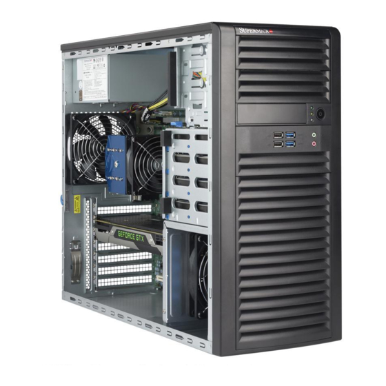
Chapter 1 Introduction 1.1 Overview The SuperWorkstation 5039C-T is a single processor workstation in the SC732D4-500B chassis with an X11SCA motherboard. It is useful as an entry level workstation or server for small and medium businesses. In addition to the motherboard and chassis, several included parts are listed below. -
Page 8: System Features
SuperWorkstation 5039C-T User's Manual 1.3 System Features The following is an overview of the main features. System Features Motherboard X11SCA Chassis SC732D4-500B Single Intel® Xeon® E Family/ 8th Intel CoreTM i3/ Pentium/ Celeron processors in Socket H4 (LGA 1511), up to... -
Page 9: Chassis Features
Chapter 1: Introduction 1.4 Chassis Features The SC732D4-500B is a mid-tower chassis. Control Panel The chassis front features a control panel to monitor functions and power off and on the system. Figure 1-1. Control Panel View Control Panel Features Item Feature Description Turns primary power on or off to the workstation from the power... -
Page 10: Front Features
SuperWorkstation 5039C-T User's Manual Front Features Figure 1-2. Chassis Front View Front Chassis Features Item Feature Description Optional Drive Area Supports two optional peripheral 5.25" drives (such as a DVD) Control Panel Front control panel (see preceding page) Two USB 2.0 ports Two USB 3.1 Gen 1 ports... -
Page 11: Rear Features
Chapter 1: Introduction Rear Features Figure 1-3. Chassis Rear View Rear Chassis Features Item Feature Description Power Supply Fixed module I/O Backpanel Rear input/output ports (see Section 4.3 and figure below) PCI-E Slots Supports four full-height, full-length PCI-E expansion cards Figure 1-4. -
Page 12: Motherboard Layout
SuperWorkstation 5039C-T User's Manual 1.5 Motherboard Layout Below is a layout of the X11SCA motherboard with jumper, connector and LED locations. See the table on the following page for brief descriptions. For detailed descriptions, pinout information and jumper settings, refer to Chapter 4. -
Page 13: Quick Reference
Chapter 1: Introduction Quick Reference Jumper Description Default Setting JBT1 Clear CMOS Short: Clear CMOS, Open: Normal JPAC1 Audio Enable Pins 1-2 (Enabled) JPL1 LAN1 Enable Pins 1-2 (Enabled) JPL2 LAN2 Enable Pins 1-2 (Enabled) JPME2 Manufacturing Mode Select Pins 1-2 (Normal) JWD1 Watch Dog Enable Pins 1-2 (Reset) - Page 14 SuperWorkstation 5039C-T User's Manual Connector Description USB 0/1 Front Accessible USB 2.0 Header USB 2/3 Back Panel USB 3.1 Gen 1 Ports USB 4/5 Front Accessible USB 2.0 Header USB 6/7 Back Panel USB 3.1 Gen 2 Ports (USB6: Type-C, USB7: Type-A) USB 8 Front Accessible USB 3.1 Gen 2 Type-C Header...
-
Page 15: Block Diagram
Chapter 1: Introduction Block Diagram CPU_PE3_P0~P7 PCIe x16 SLOT #6 SVID IMVP8 VR CPU_PE3_P8~P15 ASM1480 INTEL LGA1151 DDR4 (CHA) DIMMA1 PESLOT2_PRSNT_N PCIe x16 SLOT #4 2133/1866MHz DIMMA2 (Blue) Digital port 1 HDMI 2.0a PS175 DDR4 (CHB) DIMMB1 (Socket H4) Digital port 2 2133/1866MHz DIMMB2 (Blue) Display Port... -
Page 16: Chapter 2 Workstation Setup
SuperWorkstation 5039C-T User's Manual Chapter 2 Workstation Setup 2.1 Overview This chapter provides advice setting up your system. If your system is not already fully integrated with processors, system memory etc., refer to Chapter 3 for details on installing those components. -
Page 17: Chapter 3 Maintenance And Component Installation
Chapter 3: Maintenance and Component Installation Chapter 3 Maintenance and Component Installation This chapter provides instructions on installing and replacing main system components. To prevent compatibility issues, only use components that match the specifications and part numbers. Installation or replacement of most components require that power first be removed from the system. - Page 18 SuperWorkstation 5039C-T User's Manual Caution: Except for short periods of time, do not operate the workstation without the cover in place. The chassis cover must be in place to allow for proper airflow and to prevent overheating. Figure 3-1. Removing the Chassis Covers...
-
Page 19: Motherboard Components
• Use an Intel-certified multi-directional heatsink. • Refer to the Supermicro website for updates on CPU support. Installing the LGA1151 Processor 1. Press the load lever to release the load plate, which covers the CPU socket, from its locked position. - Page 20 SuperWorkstation 5039C-T User's Manual 2. Gently lift the load lever to open the load plate. Remove the plastic cap. 3. Use your thumb and your index finger to hold the CPU at the North center edge and the South center edge of the CPU.
- Page 21 Chapter 3: Maintenance and Component Installation 5. Do not rub the CPU against the surface or against any pins of the socket to avoid damaging the CPU or the socket. 6. With the CPU inside the socket, inspect the four corners of the CPU to make sure that the CPU is properly installed.
-
Page 22: Installing A Heatsink
SuperWorkstation 5039C-T User's Manual Installing the CPU Heatsink Do not apply thermal grease to the heatsink or the CPU--the required amount has already been applied. 1. Remove the power cord from the system. 2. Place the heatsink on top of the CPU so that the four mounting screws on the heatsink are aligned with holes on the socket. -
Page 23: Removing The Heatsink
Chapter 3: Maintenance and Component Installation Removing the Heatsink Note: We do not recommend that the CPU or the heatsink be removed. However, if you must remove the heatsink, follow the instructions below to avoid damage. 1. Remove power from the system as described in Section 3.1. 2. -
Page 24: Memory Installation
Memory Installation Memory Support The motherboard features four DIMM slots that can support up to 64 GB of of unbuffered, ECC/non-ECC DDR4 with speeds up to 2666MHz memory. Check the Supermicro website for possible updates to memory support. Memory Population Guidelines •... -
Page 25: Installing Memory
Chapter 3: Maintenance and Component Installation Installing Memory Notches 1. Push the release tab outwards on the end of the DIMM slot to unlock it. Release Tab 2. Align the key of the DIMM module with the receptive point on the memory slot. 3. -
Page 26: Motherboard Battery
SuperWorkstation 5039C-T User's Manual Motherboard Battery The motherboard uses non-volatile memory to retain system information when system power is removed. This memory is powered by a lithium battery residing on the motherboard. Replacing the Battery 1. Remove power from the system as described in section 3.1 and remove the left cover from the chassis. -
Page 27: Chassis Components
3. Rotate the drive cage outward. Release Tab (A) Drive Cage Figure 3-5. Rotating the Drive Cage Note: Enterprise level drives are recommended for use in Supermicro servers. For information on recommended drives, visit the Supermicro website at http://www.supermicro.com/products/ nfo/storage.cfm. - Page 28 SuperWorkstation 5039C-T User's Manual Installing a 3.5" Storage Drive 1. Rotate the drive cage. 2. Press the release tab on the side of the drive carrier and slide the carrier out of the drive cage. Figure 3-6. Installing Drives in the Primary Drive Cage Figure 3-7.
-
Page 29: Adding 2.5" Storage Drives
Chapter 3: Maintenance and Component Installation 5. Slide the drive assembly into the drive cage until it clicks into a locked position. 6. Connect the power and data cables to the hard drive. 7. Rotate the drive cage back.. Adding 2.5" Storage Drives Up to four 2.5"... - Page 30 SuperWorkstation 5039C-T User's Manual 4. Press the release tab on the side of the drive carrier and slide the carrier out of the drive cage. 5. If you are replacing a drive, remove the drive from the carrier by pulling the sides of the carrier outwards.
-
Page 31: Ssd Storage
Chapter 3: Maintenance and Component Installation U.2 SSD Storage One U.2 solid state storage drive is supported. The drive can be mounted in the primary 3.5" storage drive cage using an adapter (MCP-220-73102-0N) or in the optional 2.5" cage (MCP-220-73201-0N). An optional cable (CBL-SAST-0957) is required for each port. -
Page 32: Adding An M.2 Storage Card
SuperWorkstation 5039C-T User's Manual Adding an M.2 Storage Card One or two M.2 SSD cards may be installed on the motherboard. Supported cards are PCI-E 3.0 x4 (32 Gb/s) with form factors 2260, 2280 and 22110. (See Figure 3-9 for locations.) Note: If using an M.2 device with a low thermal tolerance, a heatsink should be installed on... -
Page 33: Installing An Optional Device
Chapter 3: Maintenance and Component Installation Installing an Optional Device The system supports a 3.5" optional device, such as an all-in-one card reader. Installing a 3.5" Device 1. Remove power from the system as described in section 3.1. 2. Remove the front bezel from the chassis by lifting it upwards from the bottom, and pulling off the front of the chassis. -
Page 34: System Cooling
SuperWorkstation 5039C-T User's Manual System Cooling Rear Fan The system includes a super quiet system exhaust fan that provides cooling. No tools or screws are required for installation. Installing the Rear Fan 1. Remove power from the system as described in section 3.1, and remove the left chassis cover. -
Page 35: Optional Front Fan
Chapter 3: Maintenance and Component Installation Optional Front Fan 1. Remove power from the system as described in section 3.1, and remove the left chassis cover. 2. Insert four rubber pins through the fan bracket and into the mounting holes in the fan. 3. -
Page 36: Power Supply
SuperWorkstation 5039C-T User's Manual Power Supply The power supply is auto-switching capable. This feature enables it to automatically sense the input voltage and operate at 100-240v. Changing the Power Supply 1. Remove power from the system as described in section 3.1, and remove the left chassis cover. -
Page 37: Expansion Card Installation
Chapter 3: Maintenance and Component Installation Expansion Card Installation Four standard size PCI-E expansion cards may be installed in the system. Make sure the card is supported by the slot on the motherboard. Installing PCI-E Expansion Cards Begin by removing power from the system as described in section 3.1. 1. -
Page 38: Power Connections
SuperWorkstation 5039C-T User's Manual Chapter 4 Motherboard Connections This section describes the connections on the motherboard and provides pinout definitions. Note that depending on how the system is configured, not all connections are required. The LEDs on the motherboard are also described here. A motherboard layout indicating component locations may be found in Chapter 1. -
Page 39: Headers And Connectors
Chapter 4: Motherboard Connections Secondary Power Connector JPW2 must also be connected to the power supply. This connector is used to power the processor(s). +12V 8-pin Power Pin Definitions Pin# Definition Ground +12V Required Connection 4.2 Headers and Connectors Fan Headers This motherboard has five fan headers (FAN1-5). - Page 40 SuperWorkstation 5039C-T User's Manual Thunderbolt Add-on Card Header This motherboard supports one Thunderbolt add-on card using a header located at JTBT1. Note: Support is limited to tested Thunderbolt cards that have 5-pin AIC cables. Please contact your distributor or sales agent for details.
- Page 41 The JTPM1 header is used to connect a Trusted Platform Module (TPM)/Port 80, which is available from Supermicro. A TPM/Port 80 connector is a security device that supports encryption and authentication in hard drives. It allows the motherboard to deny access if the TPM associated with the hard drive is not installed in the system.
-
Page 42: Control Panel
SuperWorkstation 5039C-T User's Manual Control Panel JF1 contains header pins for various control panel connections. See the figure below for the pin locations and definitions of the control panel buttons and LED indicators. All JF1 wires have been bundled into a single cable to simplify this connection. Make sure the red wire plugs into pin 1 as marked on the motherboard. - Page 43 Chapter 4: Motherboard Connections Power Fail LED The Power Fail LED connection is located on pins 5 and 6 of JF1. Power Fail LED Pin Definitions (JF1) Pin# Definition 3.3V PWR Supply Fail Overheat (OH)/Fan Fail Connect an LED cable to pins 7 and 8 of JF1 to use the Overheat/Fan Fail LED connections. The LED on pin 8 provides warnings of overheat or fan failure.
-
Page 44: Input/Output Ports
SuperWorkstation 5039C-T User's Manual Power LED The Power LED connection is located on pins 15 and 16 of JF1. Power LED Pin Definitions (JF1) Pin# Definition 3.3V Power LED NMI Button The non-maskable interrupt button header is located on pins 19 and 20 of JF1. - Page 45 Chapter 4: Motherboard Connections DisplayPort DisplayPort, developed by the VESA consortium, delivers digital display at a fast refresh rate. It can connect to virtually any display device using a DisplayPort adapter for devices such as VGA, DVI or HDMI. HDMI Port One HDMI (High-Definition Multimedia Interface) is used to display both high definition video and digital sound through an HDMI capable display, using a single HDMI cable (not included).
-
Page 46: Jumpers
SuperWorkstation 5039C-T User's Manual 4.4 Jumpers Explanation of Jumpers To modify the operation of the motherboard, jumpers are used to choose between optional settings. Jumpers create shorts between two pins to change the function associated with it. Pin 1 is identified with a square solder pad on the printed circuit board. See the motherboard layout page for jumper locations. - Page 47 Chapter 4: Motherboard Connections LAN Port Enable/Disable Jumpers JPL1 and JPL2 enable or disable LAN ports 1 and 2 respectively on the motherboard. The default setting is Enabled. LAN Enable/Disable Jumper Settings Jumper Setting Definition Pins 1-2 Enabled Pins 2-3 Disabled Watch Dog JWD1 controls the Watch Dog function.
-
Page 48: Led Indicators
Eight SATA 3.0 ports, supported by the Intel C246 PCH chip, are located on the motherboard. They support RAID 0, 1, 5, and 10. Note: For more information on the SATA HostRAID configuration, refer to the Intel SATA HostRAID user's guide posted on our website at http://www.supermicro.com. SATA 3.0 Connector Types Port#... -
Page 49: Chapter 5 Software
You must first configure RAID settings (if using RAID) before you install the Windows OS and the software drivers. To configure RAID settings, please refer to the RAID Configuration User Guides posted on our website at www.supermicro.com/support/manuals. Installing the Windows OS for a RAID System 1. -
Page 50: Driver Installation
SuperWorkstation 5039A-I User's Manual 5.2 Driver Installation The Supermicro FTP site contains drivers and utilities for your system at ftp://ftp.supermicro. com. Some of these must be installed, such as the chipset driver. After accessing the FTP site, go into the CDR_Images directory and locate the ISO file for your motherboard. -
Page 51: Superdoctor ® 5
5.3 SuperDoctor ® The Supermicro SuperDoctor 5 is a program that functions in a command-line or web-based interface for Windows and Linux operating systems. The program monitors such system health information as CPU temperature, system voltages, system power consumption, fan speed, and provides alerts via email or Simple Network Management Protocol (SNMP). -
Page 52: Chapter 6 Bios
SuperWorkstation 5039C-T User's Manual Chapter 6 BIOS 6.1 Introduction This chapter describes the AMI BIOS setup utility for the X11SCA and provides the instructions on navigating the setup screens. The BIOS is stored in a Flash EEPROM and can be updated. -
Page 53: Main Setup
HH:MM:SS format. Note: The time is in the 24-hour format. For example, 5:30 P.M. appears as 17:30:00. The date's default value is 01/01/2016 after RTC reset. Supermicro X11SCA (Motherboard model) BIOS Version Build Date (of the BIOS) -
Page 54: Advanced Setup Configurations
SuperWorkstation 5039C-T User's Manual 6.3 Advanced Setup Configurations Use the arrow keys to select the Advanced tab and press <Enter> to access the submenu items. Caution: Take caution when changing the Advanced settings. An incorrect value, a very high DRAM frequency, or an incorrect DRAM timing setting may make the system unstable. If this occurs, revert to the manufacture default settings. - Page 55 Chapter 6: BIOS Option ROM Messages This feature controls the display mode for Option ROM. The options are Force BIOS or Keep Current. Wait For "F1" If Error Use this feature to force the system to wait until the "F1" key is pressed if an error occurs. The options are Disabled or Enabled.
- Page 56 SuperWorkstation 5039C-T User's Manual • EIST Technology - displays whether EIST technology is supported • CPU C3 state - displays whether CPU C3 is supported • CPU C6 state - displays whether CPU C6 is supported • CPU C7 state - displays whether CPU C7 is supported •...
- Page 57 Chapter 6: BIOS This feature enables Intel CPU Advanced Encryption Standard (AES) Instructions support to enhance data integrity. The options are Disabled or Enabled. Boot performance mode This feature enables the selection of the default CPU performance during system boot. The options are Max Non-Turbo Performance, Power Saving, and Turbo Performance.
- Page 58 SuperWorkstation 5039C-T User's Manual Enhanced C-states This feature enables Enhanced C1 Power State to boost system performance. The options are Disabled or Enabled. C-State Auto Demotion When this feature is enabled, the CPU will conditionally demote C State based on un-cored auto-demote information.
- Page 59 Chapter 6: BIOS ECC Support This feature enables DDR ECC support. The options are Disabled or Enabled. Max TOLUD This feature sets the maximum TOLUD value, which specifies the “Top of Low Usable DRAM” memory space to be used by internal graphics devices, GTT Stolen Memory, and TSEG, respectively, if these devices are enabled.
- Page 60 SuperWorkstation 5039C-T User's Manual Aperture Size This feature controls the graphics aperture size. For optimal performance, select the size that matches the installed graphics card's size. The options are 128MB, 256MB, 512MB, 1024MB, and 2048MB. DVMT Pre-Allocated This feature controls the DVMT 5.0 Pre-allocated graphics memory size to be used by the internal grahics device.
- Page 61 Chapter 6: BIOS PEG Port Configuration CPU SLOT6 PCI-E 3.0 X16 This displays information if a PCI-E device is installed. SLOT6 Max Link Speed Select Auto, Gen1, Gen2, or Gen3 to set the PEG Max Link Speed. SLOT6 Power Limit Value Enter a value for the upper limit on power (in watts) supplied by the slot.
- Page 62 SuperWorkstation 5039C-T User's Manual VT-d This feature enables VT-d. The options are Disabled or Enabled. SW Guard Extensions (SGX) Select Enabled to activate the Software Guard Extensions (SGX). The options are Disabled, Enabled, and Software Controlled. Select Owner EPOCH input type There are three Owner EPOCH modes (each EPOCH is 64 bit).
- Page 63 Chapter 6: BIOS EDPC This feature enables rootport Extension for Downstream Port Containment. The options are Disabled or Enabled. SLOT7 PCIe Speed This feature controls the PCIe Speed. The options are Auto, Gen1, Gen2, and Gen3. PCI-E M.2-M2 M.2-M2 ASPM Support This feature controls the Active State Power Management (ASPM) setting.
- Page 64 SuperWorkstation 5039C-T User's Manual EDPC This feature enables rootport Extension for Downstream Port Containment. The options are Disabled or Enabled. SLOT2/M.2-M1 PCIe Speed This feature controls the PCIe Speed. The options are Auto, Gen1, Gen2, and Gen3. Frontside Audio Mode This feature controls the Frontside Audio mode.
- Page 65 Chapter 6: BIOS Serial Port Console Redirection COM1 Console Redirection Check the box to enable COM Port 1 Console Redirection, which will allow a client machine to be connected to a host machine at a remote site for networking. The options are Unchecked (Disabled) and Checked (Enabled).
- Page 66 SuperWorkstation 5039C-T User's Manual is full. Send a "Start" signal to start sending data when the receiving buffer is empty. The options are None or Hardware RTS/CTS. COM1 VT-UTF8 Combo Key Support Select Enabled to enable VT-UTF8 Combination Key support for ANSI/VT100 terminals.
- Page 67 Chapter 6: BIOS VT-UTF8 to use UTF8 encoding to map Unicode characters into one or more bytes. The options are ANSI, VT100, VT100+, and VT-UTF8. SOL Bits per second Use this feature to set the transmission speed for a serial port used in Console Redirection. Make sure that the same speed is used in the host computer and the client computer.
- Page 68 SuperWorkstation 5039C-T User's Manual SOL Legacy OS Redirection Resolution Use this feature to select the number of rows and columns used in Console Redirection for legacy OS support. The options are 80x24 or 80x25. SOL Putty KeyPad This feature selects Function Keys and KeyPad settings for Putty, which is a terminal emulator designed for the Windows OS.
- Page 69 Chapter 6: BIOS the parity bit is set to 0, and the number of 1's in data bits is odd. Select None if you do not want to send a parity bit with your data bits in transmission. Select Mark to add a mark as a parity bit to be sent along with the data bits.
- Page 70 SuperWorkstation 5039C-T User's Manual EMS Console Redirection Select Enabled to enable Emergency Out-of-Band Management Console Redirection, which will allow a client machine to be connected to a host machine at a remote site for networking. The options are Unchecked (Disabled) and Checked (Enabled).
- Page 71 Chapter 6: BIOS Aggressive LPM Support This feature enables the PCH to aggressively enter link power state. The options are Disabled or Enabled. Storage Option ROM/UEFI Driver This feature controls the execution of UEFI and legacy storage OpROM. The options are Do not launch, UEFI, and Legacy.
- Page 72 SuperWorkstation 5039C-T User's Manual AMT BIOS Configuration ASF support This feature enables Alert Standard Format (ASF) support. The options are Disabled or Enabled. USB Provisioning of AMT This feature enables AMT USB provisioning. The options are Disabled or Enabled. ...
- Page 73 Chapter 6: BIOS OEM Flags Settings MEBx hotkey Pressed This feature enables automatic MEBx hotkey presses. The options are Unchecked (Dis- abled) or Checked (Enabled). MEBx Selection Screen This feature enables the MEBx selection screen. The options are Unchecked (Disabled) or Checked (Enabled).
- Page 74 SuperWorkstation 5039C-T User's Manual High Precision Event Timer Select Enabled to activate the High Precision Event Timer (HPET) that produces periodic interrupts at a much higher frequency than a Real-time Clock (RTC) does in synchronizing multimedia streams, providing smooth playback and educing the depenency on other timestamp calculation devices, such as an x86 RDTSC Instruction embedded in the CPU.
- Page 75 Chapter 6: BIOS Onboard LAN Option ROM Type Use this feature to select the type of option ROM installed. The options are EFI or Legacy. Onboard LAN1 Option ROM Select PXE (Preboot Execution Environment) to boot the computer using a PXE device installed in a specified LAN port.
- Page 76 SuperWorkstation 5039C-T User's Manual Trusted Computing Security Device Support This feature enables BIOS support for a security device. The options are Disabled or Enabled. TPM State This feature enables an installed security device. Changing the setting will reboot the computer.
-
Page 77: Event Logs
Chapter 6: BIOS 6.4 Event Logs Use this tab page to configure Event Log settings. Change Smbios Event Log Settings Smbios Event Log Use this feature to enable all features of the SMBIOS Event Logging during system boot. The options are Disabled or Enabled. - Page 78 SuperWorkstation 5039C-T User's Manual MECI The Multiple Event Count Increment (MECI) counter counts the number of occurrences that a duplicate event must happen before the MECI counter is incremented. This is a numeric value. The default value is 1. METW The Multiple Event Time Window (METW) defines the number of minutes that must pass between duplicate log events before MECI is incremented.
-
Page 79: Security
Chapter 6: BIOS 6.5 Security Use this tab page to configure Security settings. Create Administrator and User passwords. Using ONLY an Administrator password limits access to BIOS setup. Using ONLY a User password will lock unauthorized users from booting the system and/or entering BIOS setup. -
Page 80: Boot
SuperWorkstation 5039C-T User's Manual 6.6 Boot Use this tab page to configure Boot Settings. Setup Prompt Timeout This feature controls how long (in seconds) the boot process will wait for the Setup Activation key (normally <Delete>) to be pressed before moving on. The default is 1. -
Page 81: Save & Exit
Chapter 6: BIOS 6.7 Save & Exit Use this tab page to configure Save & Exit settings. Discard Changes and Reset This option will save the changes that have been made and will reboot the system. Save Changes and Reset This option will save the changes that have been made and will reboot the system. - Page 82 SuperWorkstation 5039C-T User's Manual Boot Override IBA CL Slot 00FE v0113 This feature force boots IBA CL Slot 00FE v0113. This will restart the system. UEFI: Built-in EFI Shell This feature force boots the Built-in EFI Shell.
-
Page 83: Appendix A Bios Error Codes
When BIOS performs the Power On Self Test, it writes checkpoint codes to I/O port 0080h. If the computer cannot complete the boot process, a diagnostic card can be attached to the computer to read I/O port 0080h (Supermicro p/n AOC-LPC80-20). For information on AMI updates, please refer to http://www.ami.com/products/. -
Page 84: Appendix B Standardized Warning Statements For Ac Systems
Supermicro's Technical Support department for assistance. Only certified technicians should attempt to install or configure components. Read this appendix in its entirety before installing or configuring components in the Supermicro chassis. These warnings may also be found on our website at http://www.supermicro.com/about/... - Page 85 Appendix B: Standardized Warning Statements Warnung WICHTIGE SICHERHEITSHINWEISE Dieses Warnsymbol bedeutet Gefahr. Sie befinden sich in einer Situation, die zu Verletzungen führen kann. Machen Sie sich vor der Arbeit mit Geräten mit den Gefahren elektrischer Schaltungen und den üblichen Verfahren zur Vorbeugung vor Unfällen vertraut. Suchen Sie mit der am Ende jeder Warnung angegebenen Anweisungsnummer nach der jeweiligen Übersetzung in den übersetzten Sicherheitshinweisen, die zusammen mit diesem Gerät ausgeliefert wurden.
- Page 86 SuperWorkstation 5039C-T User's Manual . ٌ ا ك ً ف حالة و ٌ يك أى تتسبب ف اصابة جسذ ة ٌ هذا الزهز ع ٌ خطز !تحذ ز قبل أى تعول عىل أي هعذات،يك عىل علن بالوخاطز ال ا ٌجوة عي الذوائز...
- Page 87 Appendix B: Standardized Warning Statements Warnung Vor dem Anschließen des Systems an die Stromquelle die Installationsanweisungen lesen. ¡Advertencia! Lea las instrucciones de instalación antes de conectar el sistema a la red de alimentación. Attention Avant de brancher le système sur la source d'alimentation, consulter les directives d'installation. .יש...
- Page 88 SuperWorkstation 5039C-T User's Manual Warnung Dieses Produkt ist darauf angewiesen, dass im Gebäude ein Kurzschluss- bzw. Überstromschutz installiert ist. Stellen Sie sicher, dass der Nennwert der Schutzvorrichtung nicht mehr als: 250 V, 20 A beträgt. ¡Advertencia! Este equipo utiliza el sistema de protección contra cortocircuitos (o sobrecorrientes) del edificio.
- Page 89 Appendix B: Standardized Warning Statements Power Disconnection Warning Warning! The system must be disconnected from all sources of power and the power cord removed from the power supply module(s) before accessing the chassis interior to install or remove system components. 電源切断の警告...
- Page 90 SuperWorkstation 5039C-T User's Manual يجب فصم اننظاو من جميع مصادر انطاقت وإ ز انت سهك انكهرباء من وحدة امداد انطاقت قبم انىصىل إىن امنناطق انداخهيت نههيكم نتثبيج أو إ ز انت مكىناث الجهاز 경고! 시스템에 부품들을 장착하거나 제거하기 위해서는 섀시 내부에 접근하기 전에 반드시 전원...
- Page 91 Appendix B: Standardized Warning Statements Attention Il est vivement recommandé de confier l'installation, le remplacement et la maintenance de ces équipements à des personnels qualifiés et expérimentés. !אזהרה .צוות מוסמך בלבד רשאי להתקין, להחליף את הציוד או לתת שירות עבור הציוד واملدربيه...
- Page 92 SuperWorkstation 5039C-T User's Manual Warnung Diese Einheit ist zur Installation in Bereichen mit beschränktem Zutritt vorgesehen. Der Zutritt zu derartigen Bereichen ist nur mit einem Spezialwerkzeug, Schloss und Schlüssel oder einer sonstigen Sicherheitsvorkehrung möglich. ¡Advertencia! Esta unidad ha sido diseñada para instalación en áreas de acceso restringido. Sólo puede obtenerse acceso a una de estas áreas mediante la utilización de una herramienta especial,...
- Page 93 Appendix B: Standardized Warning Statements Battery Handling Warning! There is the danger of explosion if the battery is replaced incorrectly. Replace the battery only with the same or equivalent type recommended by the manufacturer. Dispose of used batteries according to the manufacturer's instructions 電池の取り扱い...
- Page 94 SuperWorkstation 5039C-T User's Manual هناك خطر من انفجار يف حالة اسحبذال البطارية بطريقة غري صحيحة فعليل اسحبذال البطارية فقط بنفس النىع أو ما يعادلها مام أوصث به الرشمة املصنعة جخلص من البطاريات املسحعملة وفقا لحعليامت الرشمة الصانعة 경고! 배터리가 올바르게 교체되지 않으면 폭발의 위험이 있습니다. 기존 배터리와 동일하거나 제...
- Page 95 Appendix B: Standardized Warning Statements ¡Advertencia! Puede que esta unidad tenga más de una conexión para fuentes de alimentación. Para cortar por completo el suministro de energía, deben desconectarse todas las conexiones. Attention Cette unité peut avoir plus d'une connexion d'alimentation. Pour supprimer toute tension et tout courant électrique de l'unité, toutes les connexions d'alimentation doivent être débranchées.
- Page 96 SuperWorkstation 5039C-T User's Manual Backplane Voltage Warning! Hazardous voltage or energy is present on the backplane when the system is operating. Use caution when servicing. バックプレーンの電圧 システムの稼働中は危険な電圧または電力が、 バックプレーン上にかかっています。 修理する際には注意く ださい。 警告 当系统正在进行时,背板上有很危险的电压或能量,进行维修时务必小心。 警告 當系統正在進行時,背板上有危險的電壓或能量,進行維修時務必小心。 Warnung Wenn das System in Betrieb ist, treten auf der Rückwandplatine gefährliche Spannungen oder Energien auf.
- Page 97 Appendix B: Standardized Warning Statements هناك خطز مه التيار الكهزبايئ أوالطاقة املىجىدة عىل اللىحة عندما يكىن النظام يعمل كه حذ ر ا عند خدمة هذا الجهاس 경고! 시스템이 동작 중일 때 후면판 (Backplane)에는 위험한 전압이나 에너지가 발생 합니다. 서비스 작업 시 주의하십시오. Waarschuwing Een gevaarlijke spanning of energie is aanwezig op de backplane wanneer het systeem in gebruik is.
- Page 98 SuperWorkstation 5039C-T User's Manual תיאום חוקי החשמל הארצי !אזהרה .התקנת הציוד חייבת להיות תואמת לחוקי החשמל המקומיים והארציים تركيب املعدات الكهربائية يجب أن ميتثل للقىاويه املحلية والىطىية املتعلقة بالكهرباء 경고! 현 지역 및 국가의 전기 규정에 따라 장비를 설치해야 합니다.
- Page 99 Appendix B: Standardized Warning Statements Attention La mise au rebut ou le recyclage de ce produit sont généralement soumis à des lois et/ou directives de respect de l'environnement. Renseignez-vous auprès de l'organisme compétent. סילוק המוצר !אזהרה .סילוק סופי של מוצר זה חייב להיות בהתאם להנחיות וחוקי המדינה التخلص...
- Page 100 SuperWorkstation 5039C-T User's Manual Warnung Gefährlich Bewegende Teile. Von den bewegenden Lüfterblätter fern halten. Die Lüfter drehen sich u. U. noch, wenn die Lüfterbaugruppe aus dem Chassis genommen wird. Halten Sie Finger, Schraubendreher und andere Gegenstände von den Öffnungen des Lüftergehäuses entfernt.
- Page 101 Verbindungskabeln, Stromkabeln und/oder Adapater, die Ihre örtlichen Sicherheitsstandards einhalten. Der Gebrauch von anderen Kabeln und Adapter können Fehlfunktionen oder Feuer verursachen. Die Richtlinien untersagen das Nutzen von UL oder CAS zertifizierten Kabeln (mit UL/CSA gekennzeichnet), an Geräten oder Produkten die nicht mit Supermicro gekennzeichnet sind.
- Page 102 .قيرح وأ لطع يف ببستي دق ىرخأ تالوحمو تالباك يأ مادختسا .ميلسلا سباقلاو لصوملا مجح لبق نم ةدمتعملا تالباكلا مادختسا تادعملاو ةيئابرهكلا ةزهجألل ةمالسلا نوناق رظحيUL وأCSA ( ةمالع لمحت يتلاوUL/CSA) لبق نم ةددحملاو ةينعملا تاجتنملا ريغ ىرخأ تادعم يأ عمSupermicro.
- Page 103 사항을 준수하여 제공되거나 지정된 연결 혹은 구매 케이블, 전원 케이블 및 AC 어댑터를 사용하십시오. 다른 케이블이나 어댑터를 사용하면 오작동이나 화재가 발생할 수 있습니다. 전기 용품 안전법은 UL 또는 CSA 인증 케이블 (코드에 UL / CSA가 표시된 케이블)을 Supermicro 가 지정한 제품 이외의 전기 장치에 사용하는 것을 금지합니다. Stroomkabel en AC-Adapter...
-
Page 104: Appendix C System Specifications
SuperWorkstation 5039C-T User's Manual Appendix C System Specifications Processor Single Intel Xeon-E Core i3, Pentium, and Celeron processors in Socket H4 (LGA 1151), up to 6 cores, 95W max TDP. Chipset Intel C246 BIOS 256 Mb AMI BIOS SPI Flash BIOS Memory Four DDR4 ECC/ non-ECC UDIMM slots, up to 2666MHz, max. - Page 105 Appendix C: System Specifications Regulatory Compliance Electromagnetic Emissions: FCC Class B, EN 55032 Class B, EN 61000-3-2/3-3, CISPR 32 Class B Electromagnetic Immunity: EN 55024/CISPR 24, (EN 61000-4-2, EN 61000-4-3, EN 61000-4-4, EN 61000-4-5, EN 61000-4-6, EN 61000-4-8, EN 61000-4-11) Other: VCCI-CISPR 32 and AS/NZS CISPR 32 Environmental: Directive 2011/65/EU and Directive 2012/19/EU Safety: CSA/EN/IEC/UL 60950-1 Compliant, UL or CSA Listed (USA and Canada), CE Marking (Europe)
-
Page 106: Appendix D Uefi Bios Recovery
Warning: Do not upgrade the BIOS unless your system has a BIOS-related issue. Flashing the wrong BIOS can cause irreparable damage to the system. In no event shall Supermicro be liable for direct, indirect, special, incidental, or consequential damages arising from a BIOS update. - Page 107 Directory of a USB device or a writeable CD/DVD. Note: If you cannot locate the "Super.ROM" file in your driver disk, visit our website at www.supermicro.com to download the BIOS image into a USB flash device and rename it to "Super.ROM" for BIOS recovery use.
- Page 108 SuperWorkstation 5039C-T User Manual Note: At this point, you may decide if you want to start the BIOS recovery. If you decide to proceed with BIOS recovery, follow the procedures below. 4. When the screen shown above displays, use the arrow keys to select the item "Proceed with flash update"...
- Page 109 Appendix D: UEFI BIOS Recovery 5. After the BIOS recovery process is completed, press any key to reboot the system.
- Page 110 SuperWorkstation 5039C-T User's Manual Appendix E 限用物質含有情況標示聲明書 Declaration of the Presence Condition of the Restricted Substances Marking 設備名稱:工作站/ Workstation 型號(型式): SYS-5039C-T (系列型號: 732- 5) Equipment name Type designation (Type) 限用物質及其化學符號 Restricted substances and its chemical symbols 六價鉻 多溴聯苯 多溴二苯醚 單元...
- Page 111 Appendix E *輸入額定: 100-240VAC, 60-50Hz, 7-3.5A *使用者不能任意拆除或替換內部配備 *設備名稱:工作站 *報驗義務人之姓名或名稱:美超微電腦股份有限公司 *報驗義務人之地址:新北市中和區建一路 150 號 3 樓...
Need help?
Do you have a question about the SuperWorkstation 5039C-T and is the answer not in the manual?
Questions and answers