Table of Contents
Advertisement
Quick Links
Advertisement
Table of Contents

Related Manuals for Supermicro SuperWorkstation 5049A-T


Summary of Contents for Supermicro SuperWorkstation 5049A-T
- Page 1 ® SuperWorkstation 5049A-T USER’S MANUAL Revision 1.0...
- Page 2 State of California, USA. The State of California, County of Santa Clara shall be the exclusive venue for the resolution of any such disputes. Supermicro's total liability for all claims will not exceed the price paid for the hardware product.
- Page 3 About this Manual This manual is written for professional system integrators and PC technicians. It provides information for the installation and use of the SuperWorkstation 5049A-T. Installation and maintenance should be performed by experienced technicians only. Please refer to the 5049A-T server specifications page on our website for updates on supported memory, processors and operating systems (http://www.supermicro.com).
-
Page 4: Table Of Contents
SuperWorkstation 5049A-T User's Manual Contents Chapter 1 Introduction 1.1 Overview ..........................8 1.2 Unpacking the System ......................8 1.3 System Features ........................9 1.4 Server Chassis Features ....................10 Control Panel ........................10 Front Features ........................11 Rear Features ........................12 1.5 Motherboard Layout ......................13 Quick Reference Table ......................14 Chapter 2 Server Installation 2.1 Overview ..........................17... - Page 5 Preface 2.5 Installing the Server into the Rack ..................26 Removing the Chassis from the Rack ................28 2.6 Control Panel Orientation ....................29 Chapter 3 Maintenance and Component Installation 3.1 Removing Power ........................31 3.2 Accessing the System ......................31 3.3 Motherboard Components ....................33 Processor and Heatsink Installation ..................33 The Xeon Scalable Processor ..................34 Assembling the Processor Package ................34...
- Page 6 SuperWorkstation 5049A-T User's Manual Chapter 4 Motherboard Connections 4.1 Power Connections ......................52 4.2 Headers and Connectors ....................53 Control Panel .........................59 4.3 Ports ...........................62 Rear I/O Ports ........................62 4.4 Jumpers ..........................66 Explanation of Jumpers ....................66 4.5 LED Indicators ........................69 Chapter 5 Software 5.1 Microsoft Windows OS Installation ..................71...
- Page 7 Super Micro Computer, Inc. 980 Rock Ave. San Jose, CA 95131 U.S.A. Tel: +1 (408) 503-8000 Fax: +1 (408) 503-8008 Email: marketing@supermicro.com (General Information) support@supermicro.com (Technical Support) Website: www.supermicro.com Europe Address: Super Micro Computer B.V. Het Sterrenbeeld 28, 5215 ML...
-
Page 8: Overview
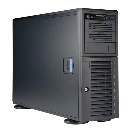
SuperWorkstation 5049A-T User's Manual Chapter 1 Introduction 1.1 Overview This chapter provides a brief outline of the functions and features of the 5049A-T SuperWorkstation. The 5049A-T is based on the X11SPA-TF motherboard and the SC743AC-1200B-SQ chassis. In addition to the motherboard and chassis, several important parts that are included with the system are listed below. -
Page 9: System Features
Chapter 1: Introduction 1.3 System Features The following table provides you with an overview of the main features of the 5049A-T. Please refer to Appendix C for additional specifications. System Features Motherboard X11SPA-TF Chassis SC743AC-1200B-SQ Supports Intel® Xeon® Scalable Processors, up to 205W TDP Socket Type Socket P0-LGA3647 Memory... -
Page 10: Server Chassis Features
SuperWorkstation 5049A-T User's Manual 1.4 Server Chassis Features Control Panel The switches and LEDs located on the control panel are described below. See Chapter 4 for details on the control panel connections. Figure 1-1. Control Panel View Control Panel Features... -
Page 11: Front Features
Chapter 1: Introduction Front Features The SC743AC-1200B-SQ is a 4U chassis. See the illustration below for the features included on the front of the chassis. Figure 1-2. Chassis Front View Front Chassis Features Item Feature Description Control Panel See previous page for details. 5.25"... -
Page 12: Rear Features
SuperWorkstation 5049A-T User's Manual Rear Features The illustration below shows the features included on the rear of the chassis. Figure 1-3. Chassis Rear View Rear Chassis Features Item Feature Description Power Supply Single 1200W power supply (p/n PWS-1K25P-PQ). 9-cm Super Quiet exhaust fan. -
Page 13: Motherboard Layout
Chapter 1: Introduction 1.5 Motherboard Layout Below is a layout of the X11SPA-TF with jumper, connector and LED locations shown. See the table on the following page for descriptions. For detailed descriptions, pinout information and jumper settings, refer to Chapter 4. USB4/5 HD AUDIO AUDIO FP... -
Page 14: Quick Reference Table
SuperWorkstation 5049A-T User's Manual Quick Reference Table Jumper Description Default Setting J9701/J9702 Manufacturing Mode Pins 1-2 (Normal) JPAC1 Audio Enable/Disable Pins 1-2 (Enabled) JPG1 VGA Enable/Disable Pins 1-2 (Enabled) JPL1/2 LAN1/LAN2 Enable/Disable Pins 1-2 (Enabled) JPME2 Intel® Manufacturing Mode Pins 1-2 (Normal) - Page 15 Chapter 1: Introduction Connector Description PCI-E 3.0 x4 M.2 Connectors. Small form factor devices and other portable PCI-E M.2-C01/C02/C03/C04 PCI-E 3.0 x4 devices for high speed NVMe SSDs Unit Identifier (UID) Switch UID-SW USB0/1 Front Access USB 2.0 Header USB2/3 Front Access USB 3.1 Gen1 Header Back Panel USB3.1 Gen1 Ports USB4/5/6/7...
- Page 16 SuperWorkstation 5049A-T User's Manual VR13 VCCP0 12V 6+1+1 PHASE VPP (2.625) 5v 205W 4 x M.2 SOCKET SSD VDDQ (1.2) 12v DDR4 (CHA) VTT_M (0.6) DIMMA1 x4 x4 x4 x4 2133/2666 (2933) MHz DIMMA2 PCI-E x16 G3 IT8898*8 DDR4 (CHB)
-
Page 17: Chapter 2 Server Installation
Chapter 2: Server Installation Chapter 2 Server Installation 2.1 Overview This chapter provides advice and instructions for mounting your system in a server rack. If your system is not already fully integrated with processors, system memory etc., refer to Chapter 3 for details on installing those specific components. Caution: Electrostatic Discharge (ESD) can damage electronic components. -
Page 18: Server Precautions
SuperWorkstation 5049A-T User's Manual • In single rack installations, stabilizers should be attached to the rack. In multiple rack in- stallations, the racks should be coupled together. • Always make sure the rack is stable before extending a server or other component from the rack. -
Page 19: Circuit Overloading
Chapter 2: Server Installation Circuit Overloading Consideration should be given to the connection of the equipment to the power supply circuitry and the effect that any possible overloading of circuits might have on overcurrent protection and power supply wiring. Appropriate consideration of equipment nameplate ratings should be used when addressing this concern. -
Page 20: Preparing The Chassis
SuperWorkstation 5049A-T User's Manual 2.3 Preparing the Chassis The chassis top tower cover and feet must be removed before rack installation. Removing the Top Tower Cover 1. Locate the blue cover lock at the rear of the cover. 2. Slide the lock to the right and push the cover forward. -
Page 21: Installing The Rails
Chapter 2: Server Installation 2.4 Installing the Rails This section provides a guideline for installing the rails to the chassis and to the rack with the included rackmount kit. Identifying the Sections of the Rack Rails The optional rackmount kit includes two rack rail assemblies. Figures 2-2 and 2-3 show the sections of one rail assembly from two different angles. -
Page 22: Assembling The Outer Rails And The Rack Brackets
SuperWorkstation 5049A-T User's Manual Assembling the Outer Rails and the Rack Brackets Each outer rail requires assembly with the rack brackets before mounting onto the rack. 1. Identify the two long brackets for the rear of each rail and the two short brackets for the front of each rail. -
Page 23: Releasing The Inner Rail From The Outer Rail
Chapter 2: Server Installation Releasing the Inner Rail from the Outer Rail 1. Locate the rail assembly. 2. Extend the rail assembly by pulling it outward. 3. Press the quick-release tab. 4. Separate the inner rail from the outer rail assembly. Figure 2-5. -
Page 24: Installing The Inner Rails To The Chassis
SuperWorkstation 5049A-T User's Manual Installing the Inner Rails to the Chassis 1. Attach the handles to the front of the chassis with three screws each. 2. Identify the left and right inner rails. They are labeled on the rails and in the figure below. -
Page 25: Installing The Outer Rails To The Rack
Chapter 2: Server Installation Installing the Outer Rails to the Rack Use the previously assembled outer rails with the rear brackets loosely attached. 1. Adjust the outer rail to fit the rack depth. Align the screw holes in the bracket ears with the holes in the rack post. -
Page 26: Installing The Server Into The Rack
SuperWorkstation 5049A-T User's Manual 2.5 Installing the Server into the Rack With rails attached to both the chassis and the rack, install the server into the rack. 1. Pull the middle rail out of the outer rail and make sure the ball bearing shuttle is locked at the front of the middle rail. - Page 27 Chapter 2: Server Installation 3. Insert and tighten the thumbscrews that hold the front of the server to the rack. Figure 2-11. Securing the Server to the Rack Note: Figure is for illustrative purposes only. Always install servers to the bottom of a rack first. Warning: Stability hazard.
-
Page 28: Removing The Chassis From The Rack
SuperWorkstation 5049A-T User's Manual Removing the Chassis from the Rack Caution! It is dangerous for a single person to off-load the heavy chassis from the rack without assistance. Be sure to have sufficient assistance supporting the chassis when removing it from the rack. -
Page 29: Control Panel Orientation
Chapter 2: Server Installation 2.6 Control Panel Orientation The server can be configured for either tower or server rack orientation. It is shipped in tower mode and can be immediately used as a desktop server. To use it in a rack, rotate the module that contains the control panel and the three drive trays ( in Figure 2-8) 90 degrees. - Page 30 SuperWorkstation 5049A-T User's Manual Rotating the Control Panel/Drive Module for Rack Mounting 1. Power down the system as described in Section 3.1 and open the chassis cover. 2. Disconnect any cables from the back of the Control Panel/Drive Module. 3. Push the module release lever to unlock the module.
-
Page 31: Chapter 3 Maintenance And Component Installation
Chapter 3: Maintenance and Component Installation Chapter 3 Maintenance and Component Installation This chapter provides instructions on installing and replacing main system components. To prevent compatibility issues, only use components that match the specifications and/or part numbers given. Installation or replacement of most components require that power first be removed from the system. - Page 32 SuperWorkstation 5049A-T User's Manual Removing the Side Tower Cover The chassis offers a removable side cover (top, if rack mounted) which allows access to the internal components. 1. Locate the latch on the cover, depress where it says "push", then lift the latch to release the cover.
-
Page 33: Motherboard Components
Check that the plastic socket dust cover is in place and none of the socket pins are bent— otherwise, contact your retailer. • Refer to the Supermicro website for updates on CPU support. • Graphics in this manual are for illustration. Your components may look slightly different. -
Page 34: The Xeon Scalable Processor
SuperWorkstation 5049A-T User's Manual The Xeon Scalable Processor Non-F model Processor F model Processor Figure 3-2. Xeon Scalable Processors Assembling the Processor Package Attach the processor to the thin processor clip to create the processor package. 1. On the top corner of the CPU, locate pin 1 (A), marked by a triangle. Also, locate notch B and notch C (and notch D for F models) on the CPU as shown below. - Page 35 Chapter 3: Maintenance and Component Installation CPU (Upside Down) Align Notch C of the CPU w/CPU LGA Lands up and Notch C of the Processor Clip Pin 1 Allow Notch C to latch on to CPU Align Notch B of the CPU and Notch B of the Processor Clip CPU/Heatsink Package (Upside Down)
-
Page 36: Assembling The Processor Heatsink Module (Phm)
SuperWorkstation 5049A-T User's Manual Assembling the Processor Heatsink Module (PHM) After creating the processor package assembly, mount it onto the heatsink to create the processor heatsink module (PHM). 1. On the heatsink label, locate "1" and the corner next to it. Turn the heatsink upside down with the thermal grease side facing up, keeping track of the "1"... -
Page 37: Removing The Dust Cover From The Cpu Socket
Chapter 3: Maintenance and Component Installation Non-Fabric CPU and Processor Clip (Upside Down) Triangle on the CPU Triangle on the Processor Clip Heatsink (Upside Down) On Locations of (C, D), the notches snap onto the heat sink’s Removing the Dust Cover from the CPU Socket mounting holes Remove the dust cover from the CPU socket, exposing the socket pins as shown below. -
Page 38: Removing The Processor Heatsink Module From The Motherboard
SuperWorkstation 5049A-T User's Manual 3. Align the two holes at diagonal corners of the PHM onto the two guide posts on the socket bracket and carefully lower the PHM onto the socket. 4. Use a T30 Torx-bit screwdriver to install four screws into the mounting holes on the socket to securely attach the PHM onto the motherboard in the sequence of 1, 2, 3, and 4, as marked on the heatsink label. -
Page 39: Memory Support
Chapter 3: Maintenance and Component Installation Removing the screws in the sequence of 4, 3, 2, 1 CPU Socket After removing the screws, lift the Processor Heatsink Printed Triangle on Motherboard Module off the CPU socket. Figure 3-8. Removing the Processor Heatsink Module Memory Support The X11SPA-TF supports up to 768GB of ECC RDIMM, 3TB of 3DS RDIMM, 1.5TB of LRDIMM, and 3TB of 3DS LRDIMM DDR4 (288-pin) ECC memory with speeds of up to 2933MHz in... -
Page 40: Memory Population Guidelines
Then, if using two DIMMs per channel, install the second DIMM in the gray slot. The following memory population sequence table was created based on guidelines provided by Intel to support Supermicro motherboards. The diagram is for illustrative purposes; your motherboard may look different. - Page 41 Chapter 3: Maintenance and Component Installation 1 CPU, 12-DIMM Slots Number of DIMMs Memory Population Sequence DIMMA1 DIMMA1,DIMMD1 DIMMA1,DIMMB1,DIMMD1 DIMMA1,DIMMB1,DIMMD1,DIMME1 DIMMA1,DIMMB1,DIMMC1,DIMMD1,DIMME1 DIMMA1,DIMMB1,DIMMC1,DIMMD1,DIMME1,DIMMF1 DIMMA1,DIMMA2,DIMMB1,DIMMC1,DIMMD1,DIMME1,DIMMF1 DIMMA1,DIMMA2,DIMMB1,DIMMC1,DIMMD1,DIMMD2,DIMME1,DIMMF1 DIMMA1,DIMMA2,DIMMB1,DIMMB2,DIMMC1,DIMMD1,DIMMD2,DIMME1,DIMMF1 DIMMA1,DIMMA2,DIMMB1,DIMMB2,DIMMC1,DIMMD1,DIMMD2,DIMME1,DIMME2,DIMMF1 DIMMA1,DIMMA2,DIMMB1,DIMMB2,DIMMC1,DIMMC2,DIMMD1,DIMMD2,DIMME1,DIMME2,DIMMF1 DIMMA1,DIMMA2,DIMMB1,DIMMB2,DIMMC1,DIMMC2,DIMMD1,DIMMD2,DIMME1,DIMME2,DIMMF1,DIMMF2 Table 3-1. DIMM Population Sequence Speed (MT/s), Voltage (V), Slot Per Channel (SPC), DIMM Capacity and DIMM Per Channel (DPC) (GB)
- Page 42 SuperWorkstation 5049A-T User's Manual Universal ID UID-LED UID-SW JPAC1 AUDIO FP JSPDIF_OUT ASpeed HD AUDIO JPUSB1 AST2500 COM1 JPWR4 USB8/9 (3.1) USB4/5(3.0) USB6/7 (3.0) USB3.1 Gen.2 USB3.1 Gen.1 USB3.1 Gen.1 LAN1 LAN2 IPMI_LAN LEDBMC JPL1 JPL2 DIMMC1 FAN D FAN C...
-
Page 43: Installing Memory
Chapter 3: Maintenance and Component Installation Installing Memory To install memory, first decide on the number of DIMMs to install. Refer to Table 3-1 for the sequence of DIMM population for the desired number of DIMMs. Populate the DIMM slots according to the sequence listed in Table 3-1. -
Page 44: Pci Expansion Card Installation
SuperWorkstation 5049A-T User's Manual PCI Expansion Card Installation The 5049A-T can accommodate standard size add-on cards populated in all slots on the X11SPA-TF serverboard. Installing PCI Expansion Cards Begin by removing power from the system as described in Section 3.1. -
Page 45: Chassis Components
Chapter 3: Maintenance and Component Installation 3.4 Chassis Components Hard Drives A total of eight SATA drives may be housed in the SC743AC-1200B-SQ chassis. The drive IDs are preconfigured as 0 through 7 in order from bottom to top (or from left to right if rackmounted). -
Page 46: Sata Backplane
SuperWorkstation 5049A-T User's Manual Figure 3-13. Mounting a Drive in a Carrier Note: Enterprise level hard disk drives are recommended for use in Supermicro chassis and servers. For information on recommended HDDs, visit the Supermicro website at http://www. supermicro.com/products/nfo/storage.cfm SATA Backplane The SATA drives plug into a drive backplane. -
Page 47: System Fans
Chapter 3: Maintenance and Component Installation System Fans The SuperWorkstation 5049A-T includes two mid-chassis fans, one rear exhaust fan, and two power supply fans. All fans are low-noise and operate in "Whisper-Quiet" mode (~28 dB). None of the fans are hot-swappable. - Page 48 SuperWorkstation 5049A-T User's Manual 10. Check that the Fan Fail LED is off. 11. Replace the chassis side cover. Figure 3-14. Removing a Mid-Chassis Fan Note: The figure is for illustrative purposes only. The number of fans may differ on the...
-
Page 49: Power Supply Fans
Chapter 3: Maintenance and Component Installation Power Supply Fans Identify the Failed Fan 1. Determine if a power supply fan has failed. An audible alarm will sound and the front control panel Power Fail LED will light up. 2. Turn off the alarm by pressing the reset button on the back of the power supply. Replace the Entire Power Supply The power supply fan cannot be replaced independently. -
Page 50: Power Supply
SuperWorkstation 5049A-T User's Manual Power Supply The SuperWorkstation 5049A-T has a single 1200 watt power supply. This power unit is equipped with low-noise technology, making the system ideal for workstation environments. The power supply has an auto-switching capability that enables it to automatically sense and operate with 100 or 240 volt inputs. - Page 51 Chapter 3: Maintenance and Component Installation Remove Screws Figure 3-15. Removing the Power Supply Screws Note: The figure is for illustrative purposes only. Some components may differ on the 5049A-T.
-
Page 52: Chapter 4 Motherboard Connections
SuperWorkstation 5049A-T User's Manual Chapter 4 Motherboard Connections This section describes the connections on the motherboard and provides pinout definitions. Note that depending on how the system is configured, not all connections are required. The LEDs on the motherboard are also described here. A serverboard layout indicating component locations may be found in Chapter 1. -
Page 53: Headers And Connectors
Chapter 4: Motherboard Connections 12V 8-pin CPU Power Connectors JPWR1/3/4 are the 8-pin 12V DC power input for the CPU. Refer to the table below for pin definitions. 12V 8-pin Power Pin Definitions Definition Pin# 1 - 4 Ground 5 - 8 +12V 4.2 Headers and Connectors Fan Headers... - Page 54 SuperWorkstation 5049A-T User's Manual M.2 Slot The X11SPA-TF has four M.2 slots. M.2 was formerly called Next Generation Form Factor (NGFF) and are used to replace mini PCI-E. M.2 supports a variety of card sizes with increased functionality and spatial efficiency. The M.2 socket on the motherboard supports PCI-E 3.0 x4 (32 Gb/s) SSD cards in the 2280 and 22110 form factors.
- Page 55 Chapter 4: Motherboard Connections TPM Header The JTPM1 header is used to connect a Trusted Platform Module (TPM)/Port 80, which is available from a third-party vendor. A TPM/Port 80 connector is a security device that supports encryption and authentication in hard drives. It allows the motherboard to deny access if the TPM associated with the hard drive is not installed in the system.
- Page 56 SuperWorkstation 5049A-T User's Manual Power SMB (I C) Header The Power System Management Bus (I C) connector (JPI C1) monitors the power supply, fan, and system temperatures. Refer to the table below for pin definitions. Power SMB Header Pin Definitions...
- Page 57 Chapter 4: Motherboard Connections Chassis Intrusion A Chassis Intrusion header is located at JL1 on the motherboard. Attach the appropriate cable from the chassis to inform you of a chassis intrusion when the chassis is opened. Refer to the table below for pin definitions. Chassis Intrusion Pin Definitions Definition...
- Page 58 SuperWorkstation 5049A-T User's Manual 4-pin BMC External I C Header A System Management Bus header for IPMI 2.0 is located at JIPMB1. Connect the appropriate cable here to use the IPMB I C connection on your system. Refer to the table below for pin definitions.
-
Page 59: Control Panel
Chapter 4: Motherboard Connections Control Panel JF1 contains header pins for various control panel connections. See the figure below for the pin locations and definitions of the control panel buttons and LED indicators. All JF1 wires have been bundled into a single cable to simplify this connection. Make sure the red wire plugs into pin 1 as marked on the motherboard. - Page 60 SuperWorkstation 5049A-T User's Manual Reset Button The Reset Button connection is located on pins 3 and 4 of JF1. Attach it to a hardware reset switch on the computer case to reset the system. Reset Button Pin Definitions (JF1) Definition...
- Page 61 Chapter 4: Motherboard Connections HDD LED The HDD LED connection is located on pins 13 and 14 of JF1. Attach a cable to pin 14 to show hard drive activity status. Refer to the table below for pin definitions. HDD LED Pin Definitions (JF1) Definition Pins...
-
Page 62: Ports
SuperWorkstation 5049A-T User's Manual 4.3 Ports SATA Ports The X11SPA-TF has eight SATA 3.0 ports (SATA0-7) supported by the C621 chipset. These SATA ports support RAID 0, 1, 5, and 10. SATA ports provide serial-link signal connections, which are faster than the connections of Parallel ATA. - Page 63 Chapter 4: Motherboard Connections COM Ports The COM ports (COM1, COM2) are located on the I/O back panel. Use this connection for serial communication. COM Port Pin Definitions Definition Definition Pin# Pin# Ground Ethernet LAN Ports Two Ethernet LAN ports and a dedicated IPMI port are located on the I/O backplane. All of these ports accept RJ45 cables.
- Page 64 Note: UID can also be triggered via IPMI on the motherboard. For more information on IPMI, please refer to the IPMI User's Guide posted on our website at http://www.supermicro.com. UID Switch...
- Page 65 Chapter 4: Motherboard Connections Universal Serial Bus (USB) Ports There are four USB 3.1 Gen 1 ports (USB4/5, USB6/7) and two USB 3.1 Gen 2 ports (USB 8/9) on the I/O back panel. The motherboard also has two front access USB 3.1 Gen 2 headers (USB10, USB11), one front access USB 2.0 header (USB0/1), and one front access 3.1 Gen 1 header (USB2/3).
-
Page 66: Jumpers
SuperWorkstation 5049A-T User's Manual 4.4 Jumpers Explanation of Jumpers To modify the operation of the motherboard, jumpers are used to choose between optional settings. Jumpers create shorts between two pins to change the function associated with it. Pin 1 is identified with a square solder pad on the printed circuit board. See the motherboard layout page for jumper locations. - Page 67 Chapter 4: Motherboard Connections VGA Enable/Disable JPG1 allows you to enable or disable the VGA port using the onboard graphics controller. The default setting is Enabled. VGA Enable/Disable Jumper Settings Definition Jumper Setting Pins 1-2 Enabled Pins 2-3 Disabled Management Engine (ME) Manufacturing Mode Close pins 2-3 of jumper JPME2 to bypass SPI flash security and force the system to operate in the manufacturing mode, which will allow the user to flash the system firmware from a host server for system setting modifications.
- Page 68 SuperWorkstation 5049A-T User's Manual 1Gb/10Gb LAN Enable/Disable JPL1/2 allows you to enable or disable the 1Gb/10Gb LAN. The default setting is Enabled. 1Gb/10Gb LAN Enable/ Disable Jumper Settings Definition Jumper Setting Pins 1-2 Enabled Pins 2-3 Disabled USB Wake-Up This jumper allows you to "wake up" the system by pressing a key on the USB keyboard or by clicking the USB mouse of your system.
-
Page 69: Led Indicators
Chapter 4: Motherboard Connections 4.5 LED Indicators Unit ID LED A rear UID LED indicator (UID-LED) is located near the UID switch on the I/O back panel. This UID indicator provides easy identification of a system unit that may need service. UID LED LED Indicator Definition... - Page 70 SuperWorkstation 5049A-T User's Manual M.2 LED M.2 LEDs are located at LE3, LE4, LE5, and LE6 on the motherboard. When a M.2 LED is blinking, its corresponding M.2 device functions normally. Refer to the table below for more information. M.2 LED State...
-
Page 71: Chapter 5 Software
USB/SATA DVD drive, or a USB flash drive, or the IPMI KVM console. 2. Retrieve the proper RST/RSTe driver. Go to the Supermicro web page for your motherboard and click on "Download the Latest Drivers and Utilities", select the proper driver, and copy it to a USB flash drive. - Page 72 SuperServer 5049A-T User's Manual 4. During Windows Setup, continue to the dialog where you select the drives on which to install Windows. If the disk you want to use is not listed, click on “Load driver” link at the bottom left corner. Figure 5-2.
-
Page 73: Driver Installation
The Supermicro website contains drivers and utilities for your system at https://www. supermicro.com/wftp/driver. Some of these must be installed, such as the chipset driver. After accessing the website, go into the CDR_Images (in the parent directory of the above link) and locate the ISO file for your motherboard. Download this file to a USB flash drive or a DVD. -
Page 74: Superdoctor 5
® 5.3 SuperDoctor The Supermicro SuperDoctor 5 is a program that functions in a command-line or web-based interface for Windows and Linux operating systems. The program monitors such system health information as CPU temperature, system voltages, system power consumption, fan speed, and provides alerts via email or Simple Network Management Protocol (SNMP). -
Page 75: Ipmi
The X11SPA-TF supports the Intelligent Platform Management Interface (IPMI). IPMI is used to provide remote access, monitoring and management. There are several BIOS settings that are related to IPMI. For general documentation and information on IPMI, please visit our website at: http://www.supermicro.com/products/nfo/IPMI.cfm. -
Page 76: Chapter 6 Uefi Bios
SuperServer 5049A-T User's Manual Chapter 6 UEFI BIOS 6.1 Introduction This chapter describes the AMIBIOS™ Setup utility for the motherboard. The BIOS is stored on a chip and can be easily upgraded using a flash program. Note: Due to periodic changes to the BIOS, some settings may have been added or deleted and might not yet be recorded in this manual. -
Page 77: Main Setup
Note: The time is in the 24-hour format. For example, 5:30 P.M. appears as 17:30:00. The date's default value is the BIOS build date after RTC reset. Supermicro X11SPA-TF BIOS Version This feature displays the version of the BIOS ROM used in the system. - Page 78 SuperServer 5049A-T User's Manual CPLD Version This feature displays the Complex Programmable Logic Device version. Memory Information Total Memory This feature displays the total size of memory available in the system.
-
Page 79: Advanced Setup Configurations
Chapter 6: UEFI BIOS 6.3 Advanced Setup Configurations Use the arrow keys to select the Advanced menu and press <Enter> to access the submenu items: Warning: Take caution when changing the Advanced settings. An incorrect value, a very high DRAM frequency, or an incorrect DRAM timing setting may make the system unstable. When this occurs, revert to default manufacturer settings. - Page 80 SuperServer 5049A-T User's Manual Wait For "F1" If Error Use this feature to force the system to wait until the "F1" key is pressed if an error occurs. The options are Disabled and Enabled. INT19 (Interrupt 19) Trap Response Interrupt 19 is the software interrupt that handles the boot disk function. When this feature is set to Immediate, the ROM BIOS of the host adapters will "capture"...
- Page 81 Chapter 6: UEFI BIOS CPU Configuration The following CPU information will display: • Processor BSP Revision • Processor Socket • Processor ID • Processor Frequency • Processor Max Ratio • Processor Min Ratio • Microcode Revision • L1 Cache RAM •...
- Page 82 SuperServer 5049A-T User's Manual Intel Virtualization Technology Use this feature to enable the Vanderpool Technology. This technology allows the system to run several operating systems simultaneously. The options are Disable and Enable. PPIN Control Select Unlock/Enable to use the Protected Processor Inventory Number (PPIN) in the system. The options are Unlock/Disable and Unlock/Enable.
- Page 83 Chapter 6: UEFI BIOS Advanced Power Management Configuration Power Technology Select Energy Efficient to support power-saving mode. Select Custom to customize system power settings. Select Disabled to disable power-saving settings. The options are Disable, Energy Efficient, and Custom. *If the feature is set to Custom, the following features will display: Power Performance Tuning (Available when "Power Technology"...
- Page 84 SuperServer 5049A-T User's Manual Turbo Mode This feature will enable dynamic control of the processor, allowing it to run above stock frequency. The options are Disable and Enable. Hardware PM State Control Hardware P-States This feature allows the user to select between OS and hardware-controlled P-states. Selecting Native Mode allows the OS to choose a P-state.
- Page 85 Chapter 6: UEFI BIOS CPU T State Control Software Controlled T-States Use this feature to enable Software Controlled T-States. The options are Disable and Enable. Chipset Configuration Warning: Setting the wrong values in the following features may cause the system to malfunction.
- Page 86 SuperServer 5049A-T User's Manual IO Directory Cache (IODC) IO Directory Cache is an 8-entry cache that stores the directory state of remote IIO writes and memory lookups, and saves directory updates. Use this feature to lower cache to cache (C2C) transfer latencies. The options are Disable, Auto, Enable for Remote InvItoM Hybrid Push, InvItoM AllocFlow, Enable for Remote InvItoM Hybrid AllocNonAlloc, and Enable for Remote InvItoM and Remote WCiLF.
- Page 87 Chapter 6: UEFI BIOS Memory Configuration Enforce POR Select POR (Plan of Record) to enforce POR restrictions on DDR4 frequency and volt- age programming. The options are POR and Disable. PPR Type Use this feature to select Post Package Repair Type. The options are Auto, Hard PPR, Soft PPR, and PPR Disabled.
- Page 88 SuperServer 5049A-T User's Manual Memory Topology This feature displays the information of onboard memory modules as detected by the BIOS. Memory RAS Configuration Static Virtual Lockstep Mode Select Enable to run the system's memory channels in lockstep mode to minimize memory access latency.
- Page 89 Chapter 6: UEFI BIOS Patrol Scrub Patrol Scrubbing is a process that allows the CPU to correct correctable memory errors detected on a memory module and send the correction to the requestor (the original source). When this feature is set to Enable, the IO hub will read and write back one cache line every 16K cycles if there is no delay caused by internal processing.
- Page 90 SuperServer 5049A-T User's Manual PCI-E Port Max Payload Size Selecting Auto for this feature will enable the motherboard to automatically detect the maximum Transaction Layer Packet (TLP) size for the connected PCI-E device, allowing for maximum I/O efficiency. Selecting 128B or 256B will designate maximum packet size of 128 or 256.
- Page 91 Chapter 6: UEFI BIOS PassThrough DMA Use this feature to allow devices such as network cards to access the system memory without using a processor. Select Enable to use the Non-Isoch VT-d Engine Pass Through Direct Memory Access (DMA) support. The options are Enable and Disable. Use this feature to enable Non-Isoch VT-d Engine Address Translation Services (ATS) support.
- Page 92 SuperServer 5049A-T User's Manual VMD Config for PStack1 Intel VMD for Volume Management Device Select Enable to use the Intel Volume Management Device Technology for this stack. The options are Disable and Enable. *If the feature above is set to Enable, the following features will become avail- able for configuration: CPU SLOT7 PCI-E 3.0 x16 VMD/CPU SLOT6 PCI-E 3.0 x8 VMD (Available when the device is detected by the system)
- Page 93 Chapter 6: UEFI BIOS • USB Module Version • USB Devices Legacy USB Support This feature enables support for USB 2.0 and older. The options are Enabled, Disabled, and Auto. XHCI Hand-off When this feature is disabled, the motherboard will not support USB 3.0. The options are Enabled and Disabled.
- Page 94 SuperServer 5049A-T User's Manual Workstation Me Configuration (for X11SPA-T only) The following General ME Configuration will display: • Oper. Firmware Version • Me Firmware • Me Firmware SKU • Backup Firmware Version • Recovery Firmware Version • ME Firmware Status #1 •...
- Page 95 Chapter 6: UEFI BIOS SATA Port 0 ~ Port 7 This feature displays the information detected on the installed SATA drive on the particular SATA port. • Model number of drive and capacity • Software Preserve Support Port 0 ~ Port 7 Hot Plug Set this feature to Enable for hot plug support, which will allow the user to replace a SATA drive without shutting down the system.
- Page 96 SuperServer 5049A-T User's Manual Maximum Read Request Use this feature to select the Maximum Read Request size of the PCI-Express device, or select Auto to allow the System BIOS to determine the value. The options are Auto, 128 Bytes, 256 Bytes, 512 Bytes, 1024 Bytes, 2048 Bytes, and 4096 Bytes. MMCFG Base Use this feature to select the low base address for PCI-E adapters to increase base memory.
- Page 97 Chapter 6: UEFI BIOS CPU SLOT7 PCI-E 3.0 x16 OPROM Use this feature to select which firmware type to be loaded for the add-on card in this slot. The options are Disabled, Legacy, and EFI. M.2C01 PCI-E 3.0 x4 OPROM Use this feature to select which firmware type to be loaded for the add-on card in this slot.
- Page 98 SuperServer 5049A-T User's Manual Network Stack Configuration Network Stack Select Enabled to enable PXE (Preboot Execution Environment) or UEFI (Unified Extensible Firmware Interface) for network stack support. The options are Enabled and Disabled. IPv4 PXE Support Select Enabled to enable IPv4 PXE boot support. The options are Disabled and Enabled. IPv4 HTTP Support Select Enabled to enable IPv4 HTTP boot support.
- Page 99 Chapter 6: UEFI BIOS Change Settings This feature specifies the base I/O port address and the Interrupt Request address of a serial port specified by the user. Select Auto to allow the BIOS to automatically assign the base I/O and IRQ address. The options for Serial Port 1 are Auto, (IO=3F8h; IRQ=4;), (IO=2F8h;...
- Page 100 SuperServer 5049A-T User's Manual COM1 Terminal Type This feature allows the user to select the target terminal emulation type for Console Redirection. Select VT100 to use the ASCII Character set. Select VT100+ to add color and function key support. Select ANSI to use the Extended ASCII Character Set. Select VT-UTF8 to use UTF8 encoding to map Unicode characters into one or more bytes.
- Page 101 Chapter 6: UEFI BIOS COM1 Resolution 100x31 Select Enabled for extended-terminal resolution support. The options are Disabled and Enabled. COM1 Legacy OS Redirection Resolution Use this feature to select the number of rows and columns used in Console Redirection for legacy OS support. The options are 80x24 and 80x25. COM1 Putty KeyPad This feature selects the settings for Function Keys and KeyPad used for Putty, which is a terminal emulator designed for the Windows OS.
- Page 102 SuperServer 5049A-T User's Manual COM2 Data Bits Use this feature to set the data transmission size for Console Redirection. The options are 7 Bits and 8 Bits. COM2 Parity A parity bit can be sent along with regular data bits to detect data transmission errors. Select Even if the parity bit is set to 0, and the number of 1's in data bits is even.
- Page 103 Chapter 6: UEFI BIOS COM2 Redirection After BIOS POST Use this feature to enable or disable legacy Console Redirection after BIOS POST. When set to Bootloader, legacy Console Redirection is disabled before booting the OS. When set to Always Enable, legacy Console Redirection remains enabled when booting the OS. The options are Always Enable and BootLoader.
- Page 104 SuperServer 5049A-T User's Manual Flow Control Use this feature to set the flow control for Console Redirection to prevent data loss caused by buffer overflow. Send a "Stop" signal to stop sending data when the receiving buffer is full. Send a "Start" signal to start sending data when the receiving buffer is empty. The options are None, Hardware RTS/CTS, and Software Xon/Xoff.
- Page 105 Chapter 6: UEFI BIOS SHA-1 PCR Bank Use this feature to disable or enable the SHA-1 Platform Configuration Register (PCR) bank for the installed TPM device. The options are Disabled and Enabled. SHA256 PCR Bank Use this feature to disable or enable the SHA256 Platform Configuration Register (PCR) bank for the installed TPM device.
- Page 106 SuperServer 5049A-T User's Manual Boot URI A new Boot Option will be created according to this Boot URI. TLS Authenticate Configuration Server CA Configuration Enroll Certification Enroll Cert Using File Cert GUID Commit Changes and Exit Discard Changes and Exit Delete Certification iSCSI Configuration iSCSI Initiator Name...
-
Page 107: Event Logs
Chapter 6: UEFI BIOS 6.4 Event Logs Use this feature to configure Event Log settings. Change SMBIOS Event Log Settings Enabling/Disabling Options SMBIOS Event Log Change this feature to enable or disable all features of the SMBIOS Event Logging during system boot. - Page 108 SuperServer 5049A-T User's Manual SMBIOS Event Log Standard Settings Log System Boot Event This feature toggles the System Boot Event logging to enabled or disabled. The options are Disabled and Enabled. MECI The Multiple Event Count Increment (MECI) counter counts the number of occurences that a duplicate event must happen before the MECI counter is incremented.
-
Page 109: Ipmi
Chapter 6: UEFI BIOS 6.5 IPMI Use this feature to configure Intelligent Platform Management Interface (IPMI) settings. BMC Firmware Revision This feature indicates the IPMI firmware revision used in your system. IPMI Status (Baseboard Management Controller) This feature indicates the status of the IPMI firmware installed in your system. System Event Log Enabling/Disabling Options SEL Components... - Page 110 SuperServer 5049A-T User's Manual When SEL is Full This feature allows the user to decide what the BIOS should do when the system event log is full. Select Erase Immediately to erase all events in the log when the system event log is full.
- Page 111 Chapter 6: UEFI BIOS Station MAC Address This feature displays the Station MAC address for this computer. Mac addresses are 6 two- digit hexadecimal numbers. Gateway IP Address This feature displays the Gateway IP address for this computer. This should be in decimal and in dotted quad form (i.e., 172.31.0.1).
-
Page 112: Security
SuperServer 5049A-T User's Manual 6.6 Security This menu allows the user to configure the following security settings for the system. Administrator Password Press Enter to create a new, or change an existing, Administrator password. User Password Press Enter to create a new, or change an existing, User password. Password Check Select Setup for the system to check for a password at Setup. - Page 113 Chapter 6: UEFI BIOS Secure Boot Mode Use this feature to configure Secure Boot variables without authentication. The options are Standard and Custom. CSM Support Select Enabled to support the EFI Compatibility Support Module (CSM), which provides compatibility support for traditional legacy BIOS for system boot. The options are Enabled and Disabled.
- Page 114 SuperServer 5049A-T User's Manual Restore DB defaults This feature allows the user to restore DB variables to factory default. The options are Yes and No. Secure Boot Variables This feature allows the user to decide if all secure boot variables should be saved. ...
- Page 115 Chapter 6: UEFI BIOS Forbidden Signatures Update Select Yes to load the DBX from the manufacturer's defaults. Select No to load the DBX from a file. The options are Yes and No. Append Select Yes to add the DBX from the manufacturer's defaults to the existing DBX. Select No to load the DBX from a file.
-
Page 116: Boot
SuperServer 5049A-T User's Manual 6.7 Boot Use this feature to configure Boot settings. Boot Mode Select Use this feature to select the type of device that the system is going to boot from. The options are Legacy, UEFI, and Dual. Legacy to EFI Support Select Enabled to boot EFI OS support after Legacy boot order has failed. - Page 117 Chapter 6: UEFI BIOS • Boot Option #6 • Boot Option #7 • Boot Option #8 • Boot Option #9 • Boot Option #10 • Boot Option #11 • Boot Option #12 • Boot Option #13 • Boot Option #14 •...
- Page 118 SuperServer 5049A-T User's Manual Delete Boot Option Use this feature to remove an EFI boot option from the boot priority list. The options are Select one to Delete and UEFI: Built-in EFI Shell. UEFI Application Boot Priorities This feature sets the system boot order of detected devices. The options are UEFI: Built- in EFI Shell and Disabled.
-
Page 119: Save & Exit
Chapter 6: UEFI BIOS 6.8 Save & Exit Select the Save & Exit tab from the BIOS setup screen to configure the settings below: Save Options Discard Changes and Exit Select this feature to quit the BIOS Setup without making any permanent changes to the system configuration, and reboot the computer. - Page 120 SuperServer 5049A-T User's Manual Default Options Restore Optimized Defaults To set this feature, select Restore Defaults from the Save & Exit menu and press <Enter>. These are factory settings designed for maximum system stability, but not for maximum performance. Save As User Defaults To set this feature, select Save as User Defaults from the Save &...
-
Page 121: Appendix A Bios Codes
Appendix A: BIOS Codes Appendix A BIOS Codes A.1 BIOS Error POST (Beep) Codes During the POST (Power-On Self-Test) routines, which are performed each time the system is powered on, errors may occur. Non-fatal errors are those which, in most cases, allow the system to continue the boot-up process. - Page 122 When BIOS performs the Power On Self Test, it writes checkpoint codes to I/O port 0080h. If the computer cannot complete the boot process, a diagnostic card can be attached to the computer to read I/O port 0080h (Supermicro p/n AOC-LPC80-20). For information on AMI updates, please refer to http://www.ami.com/products/.
-
Page 123: Appendix B Standardized Warning Statements For Ac Systems
Supermicro's Technical Support department for assistance. Only certified technicians should attempt to install or configure components. Read this appendix in its entirety before installing or configuring components in the Supermicro chassis. These warnings may also be found on our website at http://www.supermicro.com/about/... - Page 124 SuperWorkstation 5049A-T User's Manual Warnung WICHTIGE SICHERHEITSHINWEISE Dieses Warnsymbol bedeutet Gefahr. Sie befinden sich in einer Situation, die zu Verletzungen führen kann. Machen Sie sich vor der Arbeit mit Geräten mit den Gefahren elektrischer Schaltungen und den üblichen Verfahren zur Vorbeugung vor Unfällen vertraut. Suchen Sie mit der am Ende jeder Warnung angegebenen Anweisungsnummer nach der jeweiligen Übersetzung in den übersetzten Sicherheitshinweisen, die zusammen mit diesem Gerät...
- Page 125 Appendix B: Standardized Warning Statements . ٌ ا ك ً ف حالة و ٌ يك أى تتسبب ف اصابة جسذ ة ٌ هذا الزهز ع ٌ خطز !تحذ ز قبل أى تعول عىل أي هعذات،يك عىل علن بالوخاطز ال ا ٌجوة عي الذوائز ٍ...
- Page 126 SuperWorkstation 5049A-T User's Manual Warnung Vor dem Anschließen des Systems an die Stromquelle die Installationsanweisungen lesen. ¡Advertencia! Lea las instrucciones de instalación antes de conectar el sistema a la red de alimentación. Attention Avant de brancher le système sur la source d'alimentation, consulter les directives d'installation.
- Page 127 Appendix B: Standardized Warning Statements Warnung Dieses Produkt ist darauf angewiesen, dass im Gebäude ein Kurzschluss- bzw. Überstromschutz installiert ist. Stellen Sie sicher, dass der Nennwert der Schutzvorrichtung nicht mehr als: 250 V, 20 A beträgt. ¡Advertencia! Este equipo utiliza el sistema de protección contra cortocircuitos (o sobrecorrientes) del edificio.
- Page 128 SuperWorkstation 5049A-T User's Manual Power Disconnection Warning Warning! The system must be disconnected from all sources of power and the power cord removed from the power supply module(s) before accessing the chassis interior to install or remove system components. 電源切断の警告...
- Page 129 Appendix B: Standardized Warning Statements يجب فصم اننظاو من جميع مصادر انطاقت وإ ز انت سهك انكهرباء من وحدة امداد انطاقت قبم انىصىل إىن امنناطق انداخهيت نههيكم نتثبيج أو إ ز انت مكىناث الجهاز 경고! 시스템에 부품들을 장착하거나 제거하기 위해서는 섀시 내부에 접근하기 전에 반드시 전원 공급장치로부터...
- Page 130 SuperWorkstation 5049A-T User's Manual Attention Il est vivement recommandé de confier l'installation, le remplacement et la maintenance de ces équipements à des personnels qualifiés et expérimentés. !אזהרה .צוות מוסמך בלבד רשאי להתקין, להחליף את הציוד או לתת שירות עבור הציוד...
- Page 131 Appendix B: Standardized Warning Statements Warnung Diese Einheit ist zur Installation in Bereichen mit beschränktem Zutritt vorgesehen. Der Zutritt zu derartigen Bereichen ist nur mit einem Spezialwerkzeug, Schloss und Schlüssel oder einer sonstigen Sicherheitsvorkehrung möglich. ¡Advertencia! Esta unidad ha sido diseñada para instalación en áreas de acceso restringido. Sólo puede obtenerse acceso a una de estas áreas mediante la utilización de una herramienta especial, cerradura con llave u otro medio de seguridad.
- Page 132 SuperWorkstation 5049A-T User's Manual Battery Handling Warning! There is the danger of explosion if the battery is replaced incorrectly. Replace the battery only with the same or equivalent type recommended by the manufacturer. Dispose of used batteries according to the manufacturer's instructions 電池の取り扱い...
- Page 133 Appendix B: Standardized Warning Statements هناك خطر من انفجار يف حالة اسحبذال البطارية بطريقة غري صحيحة فعليل اسحبذال البطارية فقط بنفس النىع أو ما يعادلها مام أوصث به الرشمة املصنعة جخلص من البطاريات املسحعملة وفقا لحعليامت الرشمة الصانعة 경고! 배터리가 올바르게 교체되지 않으면 폭발의 위험이 있습니다. 기존 배터리와 동일하거나 제 조사에서...
- Page 134 SuperWorkstation 5049A-T User's Manual ¡Advertencia! Puede que esta unidad tenga más de una conexión para fuentes de alimentación. Para cortar por completo el suministro de energía, deben desconectarse todas las conexiones. Attention Cette unité peut avoir plus d'une connexion d'alimentation. Pour supprimer toute tension et tout courant électrique de l'unité, toutes les connexions d'alimentation doivent être débranchées.
- Page 135 Appendix B: Standardized Warning Statements Backplane Voltage Warning! Hazardous voltage or energy is present on the backplane when the system is operating. Use caution when servicing. バックプレーンの電圧 システムの稼働中は危険な電圧または電力が、 バックプレーン上にかかっています。 修理する際には注意く ださい。 警告 当系统正在进行时,背板上有很危险的电压或能量,进行维修时务必小心。 警告 當系統正在進行時,背板上有危險的電壓或能量,進行維修時務必小心。 Warnung Wenn das System in Betrieb ist, treten auf der Rückwandplatine gefährliche Spannungen oder Energien auf.
- Page 136 SuperWorkstation 5049A-T User's Manual هناك خطز مه التيار الكهزبايئ أوالطاقة املىجىدة عىل اللىحة عندما يكىن النظام يعمل كه حذ ر ا عند خدمة هذا الجهاس 경고! 시스템이 동작 중일 때 후면판 (Backplane)에는 위험한 전압이나 에너지가 발생 합니다. 서비스 작업 시 주의하십시오.
- Page 137 Appendix B: Standardized Warning Statements תיאום חוקי החשמל הארצי !אזהרה .התקנת הציוד חייבת להיות תואמת לחוקי החשמל המקומיים והארציים تركيب املعدات الكهربائية يجب أن ميتثل للقىاويه املحلية والىطىية املتعلقة بالكهرباء 경고! 현 지역 및 국가의 전기 규정에 따라 장비를 설치해야 합니다. Waarschuwing Bij installatie van de apparatuur moet worden voldaan aan de lokale en nationale elektriciteitsvoorschriften.
- Page 138 SuperWorkstation 5049A-T User's Manual Attention La mise au rebut ou le recyclage de ce produit sont généralement soumis à des lois et/ou directives de respect de l'environnement. Renseignez-vous auprès de l'organisme compétent. סילוק המוצר !אזהרה .סילוק סופי של מוצר זה חייב להיות בהתאם להנחיות וחוקי המדינה...
- Page 139 Appendix B: Standardized Warning Statements Warnung Gefährlich Bewegende Teile. Von den bewegenden Lüfterblätter fern halten. Die Lüfter drehen sich u. U. noch, wenn die Lüfterbaugruppe aus dem Chassis genommen wird. Halten Sie Finger, Schraubendreher und andere Gegenstände von den Öffnungen des Lüftergehäuses entfernt.
- Page 140 Verbindungskabeln, Stromkabeln und/oder Adapater, die Ihre örtlichen Sicherheitsstandards einhalten. Der Gebrauch von anderen Kabeln und Adapter können Fehlfunktionen oder Feuer verursachen. Die Richtlinien untersagen das Nutzen von UL oder CAS zertifizierten Kabeln (mit UL/CSA gekennzeichnet), an Geräten oder Produkten die nicht mit Supermicro gekennzeichnet sind.
- Page 141 حجم املوصل والقابس السليم. استخدام أي كابالت ومحوالت أخرى قد يتسبب يف عطل أو حريق. يحظر قانون السالمة لألجهزة الكهربائية واملعدات استخدام الكابالت املعتمدة من قبلUL أوCSA ( والتي تحمل عالمةUL/CSA) مع أي معدات أخرى غري املنتجات املعنية واملحددة من قبلSupermicro.
- Page 142 사항을 준수하여 제공되거나 지정된 연결 혹은 구매 케이블, 전원 케이블 및 AC 어댑터를 사용하십시오. 다른 케이블이나 어댑터를 사용하면 오작동이나 화재가 발생할 수 있습니다. 전기 용품 안전법은 UL 또는 CSA 인증 케이블 (코드에 UL / CSA가 표시된 케이블)을 Supermicro 가 지정한 제품 이외의 전기 장치에 사용하는 것을 금지합니다. Stroomkabel en AC-Adapter...
-
Page 143: Appendix C System Specifications
Appendix C: System Specifications Appendix C System Specifications Processors Supports Intel® Xeon® Scalable Processors, up to 205W TDP. Note: Please refer to the motherboard specifications pages on our website for updates to supported processors. Chipset Intel C621 chipset BIOS 256Mb AMI BIOS® SPI Flash ROM ACPI 6.0, Plug and Play (PnP), BIOS rescue hot-key, riser card auto detection support, and SMBIOS 3.0 or later Memory Up to 768GB of RDIMM, 3TB of 3DS RDIMM, 1.5TB of LRDIMM, and 3TB of 3DS LRDIMM DDR4 (288-pin) ECC memory with... - Page 144 SuperWorkstation 5049A-T User's Manual Regulatory Compliance Electromagnetic Emissions: FCC Class B, EN 55032 Class B, EN 61000-3-2/3-3, CISPR 32 Class B Electromagnetic Immunity: EN 55024/CISPR 24, (EN 61000-4-2, EN 61000-4-3, EN 61000-4-4, EN 61000-4-5, EN 61000-4-6, EN 61000-4-8, EN 61000-4-11)
-
Page 145: Appendix D Uefi Bios Recovery
Warning: Do not upgrade the BIOS unless your system has a BIOS-related issue. Flashing the wrong BIOS can cause irreparable damage to the system. In no event shall Supermicro be liable for direct, indirect, special, incidental, or consequential damages arising from a BIOS update. - Page 146 SuperWorkstation 5049A-T User's Manual The file system supported by UEFI is FAT (including FAT12, FAT16, and FAT32) which is installed on a bootable or non-bootable USB-attached device. However, the BIOS might need several minutes to locate the SUPER.ROM file if the media size becomes too large due to the huge volumes of folders and files stored in the device.
- Page 147 Appendix D: UEFI BIOS Recovery 4. After locating the new BIOS binary image, the system will enter the BIOS Recovery menu as shown below. Note: At this point, you may decide if you want to start the BIOS recovery. If you decide to proceed with BIOS recovery, follow the procedures below.
- Page 148 SuperWorkstation 5049A-T User's Manual 6. After the BIOS recovery process is completed, press any key to reboot the system. 7. Using a different system, extract the BIOS package into a USB flash drive. 8. Press <Del> continuously during system boot to enter the BIOS setup utility. From the top of the tool bar, click on Boot and press <Enter>...
- Page 149 Appendix D: UEFI BIOS Recovery 9. When the UEFI Shell prompt appears, type fs# to change the device directory path. Go to the directory that contains the BIOS package you extracted earlier from Step 7. Enter flash.nsh BIOSname.### at the prompt to start the BIOS update process. Note: Do not interrupt this process until the BIOS flashing is complete.
Need help?
Do you have a question about the SuperWorkstation 5049A-T and is the answer not in the manual?
Questions and answers