Table of Contents
Advertisement
Quick Links
Advertisement
Table of Contents

Related Manuals for Supermicro SuperWorkstation 5038A-I


Summary of Contents for Supermicro SuperWorkstation 5038A-I
- Page 1 uper orkstation 5038A-I USER’S MANUAL 1.0b...
- Page 2 This product, including software and documentation, is the property of Supermicro and/or its licensors, and is supplied only under a license. Any use or reproduction of this product is not allowed, except as expressly permitted by the terms of said license.
- Page 3 903B chassis. Chapter 2: Server Installation This chapter describes the steps necessary to set up the SuperWorkstation 5038A-I and to check out the server configuration prior to powering-up the system. If your system was ordered without processor and memory components, this chapter will refer you to the appropriate sections of the manual for their installation.
- Page 4 uper orkstation 5038A-I User's Manual Chapter 5: Advanced Motherboard Setup Chapter 5 provides detailed information on the X10SRA motherboard, including the locations and functions of connections, headers and jumpers. Refer to this chapter when adding or removing processors or main memory and when reconfiguring the motherboard.
- Page 5 Preface Notes...
-
Page 6: Table Of Contents
Chassis Features .................... 1-3 System Power ....................1-3 SATA Support ....................1-3 Front Control Panel ..................1-3 Cooling System ....................1-3 Contacting Supermicro ..................1-5 Chapter 2 Installation Overview ......................2-1 Unpacking the System ..................2-1 Chapter 3 System Interface Overview ...................... - Page 7 Table of Contents Backplane Voltage ..................4-13 Comply with Local and National Electrical Codes ........4-14 Product Disposal ................... 4-15 Hot Swap Fan Warning ................. 4-16 Power Cable and AC Adapter ..............4-18 Chapter 5 Advanced Motherboard Setup Handling the Motherboard ................5-1 Cautions ......................
- Page 8 uper orkstation 5038A-I User's Manual Removing and Installing Optional 2.5" Hard Drives ........6-11 Power Supply ....................6-13 Chapter 7 BIOS Introduction ...................... 7-1 Starting BIOS GUI Setup Utility ..............7-1 How To Change the Configuration Data ............7-2 How to Start the Setup Utility ................. 7-3 Saving and Loading ..................
-
Page 9: Chapter 1 Introduction
SC732D3-903B mid-tower/3U chassis and the X10SRA Intel® Xeon® processor motherboard. Please refer to our website for information on operating systems that have been certified for use with the SuperWorkstation 5038A-I. In addition to the motherboard and chassis, various hardware components have been included with the 5038A-I, as listed below: •... -
Page 10: Motherboard Features
5038A-I User's Manual Motherboard Features At the heart of the SuperWorkstation 5038A-I lies the X10SRA, a single processor motherboard based on the Intel® C612 Express chipset. Below are the main fea- tures of the X10SRA. (See Figure 1-1 for a block diagram of the chipset). -
Page 11: Chassis Features
Chapter 1: Introduction Chassis Features The 5038A-I is a mid-tower chassis with Whisper Quiet operation. The following is a general outline of the main features of the SC743D3-903B chassis. System Power The 5038A-I features a single 900W Gold Level multi-outlet power supply with PMBus, ideal for use in a workstation environment. - Page 12 uper orkstation 5038A-I User's Manual Figure 1-1. Intel C612 Express Chipset: System Block Diagram Note: This is a general block diagram. Please see Chapter 5 for details. 9.6G DDR-IV DDR-IV DMI2 DMI2 9.6G SLOT1 PCI-E X16 G3 PCI-E X16 G3 PCI-E X16 G3 SLOT3 PCI-E X8 G3...
-
Page 13: Contacting Supermicro
Super Micro Computer, Inc. 980 Rock Ave. San Jose, CA 95131 U.S.A. Tel: +1 (408) 503-8000 Fax: +1 (408) 503-8008 Email: marketing@supermicro.com (General Information) support@supermicro.com (Technical Support) Website: www.supermicro.com Europe Address: Super Micro Computer B.V. Het Sterrenbeeld 28, 5215 ML... - Page 14 uper orkstation 5038A-I User's Manual Notes...
-
Page 15: Chapter 2 Installation
Chapter 2 Installation Overview This chapter provides a quick setup checklist to get your SuperWorkstation 5038A-I up and running. Following these steps in the order given should enable you to have the system operational within a minimum amount of time. - Page 16 uper orkstation 5038A-I User's Manual Notes...
-
Page 17: Chapter 3 System Interface
Chapter 3: System Interface Chapter 3 System Interface Overview The control panel on the 5038A-I has several LEDs and a power button. These LEDs keep you constantly informed of the overall status of the system and the activity and health of specific components. Control Panel Buttons There is single power on/off push-button located on the front of the chassis. -
Page 18: Hdd
uper orkstation 5038A-I User's Manual Indicates channel activity on the SATA drive and/or DVD-ROM drive when flashing. Information LED Alerts operator of several states, as noted in the table below. Information LED Status Description An overheat condition has occurred. Continuously on and red (This may be caused by cable congestion.) Blinking red (1Hz) Fan failure, check for an inoperative fan. -
Page 19: Chapter 4 Standardized Warning Statements For Ac Systems
The following statements are industry standard warnings, provided to warn the user of situations which have the potential for bodily injury. Should you have questions or experience difficulty, contact Supermicro's Technical Support department for assistance. Only certified technicians should attempt to install or configure components. - Page 20 uper orkstation 5038A-I User's Manual Warnung WICHTIGE SICHERHEITSHINWEISE Dieses Warnsymbol bedeutet Gefahr. Sie befinden sich in einer Situation, die zu Verletzungen führen kann. Machen Sie sich vor der Arbeit mit Geräten mit den Gefahren elektrischer Schaltungen und den üblichen Verfahren zur Vorbeugung vor Unfällen vertraut.
- Page 21 Chapter 4: Warning Statements for AC Systems . ٌ ا ك ً ف حالة و ٌ يك أى تتسبب ف اصابة جسذ ة ٌ هذا الزهز ع ٌ خطز !تحذ ز قبل أى تعول عىل أي هعذات،يك عىل علن بالوخاطز ال ا ٌ جوة عي الذوائز ٍ...
-
Page 22: Installation Instructions
uper orkstation 5038A-I User's Manual Installation Instructions Warning! Read the installation instructions before connecting the system to the power source. 設置手順書 システムを電源に接続する前に、 設置手順書をお読み下さい。 警告 将此系统连接电源前,请先阅读安装说明。 警告 將系統與電源連接前,請先閱讀安裝說明。 Warnung Vor dem Anschließen des Systems an die Stromquelle die Installationsanweisungen lesen. ¡Advertencia! Lea las instrucciones de instalación antes de conectar el sistema a la red de alimentación. -
Page 23: Circuit Breaker
Chapter 4: Warning Statements for AC Systems Circuit Breaker Warning! This product relies on the building's installation for short-circuit (overcurrent) protection. Ensure that the protective device is rated not greater than: 250 V, 20 A. サーキッ ト ・ ブレーカー この製品は、 短絡 (過電流) 保護装置がある建物での設置を前提としています。 保護装置の定格が250 V、... -
Page 24: Power Disconnection Warning
uper orkstation 5038A-I User's Manual هذا املنتج يعتمد عىل معداث الحاميت مه الدوائ ر القصرية التي تم تثبيتها يف املبنى 20A, 250V : تأكد من أن تقييم الجهاز الوقايئ ليس أكرث من 경고! 이 제품은 전원의 단락(과전류)방지에 대해서 전적으로 건물의 관련 설비에 의존합니다. - Page 25 Chapter 4: Warning Statements for AC Systems ¡Advertencia! El sistema debe ser disconnected de todas las fuentes de energía y del cable eléctrico quitado de los módulos de fuente de alimentación antes de tener acceso el interior del chasis para instalar o para quitar componentes de sistema. Attention Le système doit être débranché...
-
Page 26: Equipment Installation
uper orkstation 5038A-I User's Manual Equipment Installation Warning! Only trained and qualified personnel should be allowed to install, replace, or service this equipment. 機器の設置 トレーニングを受け認定された人だけがこの装置の設置、 交換、 またはサービスを許可 されています。 警告 只有经过培训且具有资格的人员才能进行此设备的安装、更换和维修。 警告 只有經過受訓且具資格人員才可安裝、更換與維修此設備。 Warnung Das Installieren, Ersetzen oder Bedienen dieser Ausrüstung sollte nur geschultem, qualifiziertem Personal gestattet werden. -
Page 27: Restricted Area
Chapter 4: Warning Statements for AC Systems Waarschuwing Deze apparatuur mag alleen worden geïnstalleerd, vervangen of hersteld door geschoold en gekwalificeerd personeel. Restricted Area Warning! This unit is intended for installation in restricted access areas. A restricted access area can be accessed only through the use of a special tool, lock and key, or other means of security. -
Page 28: Battery Handling
uper orkstation 5038A-I User's Manual אזור עם גישה מוגבלת !אזהרה יש להתקין את היחידה באזורים שיש בהם הגבלת גישה. הגישה ניתנת בעזרת (.'כלי אבטחה בלבד (מפתח, מנעול וכד . تخصيص هذه انىحذة نترك ب ُها ف مناطق محظورة تم ، م َ كن انىصىل إن منطقت محظورة فقط من خالل استخذاو أداة خاصت أو... - Page 29 Chapter 4: Warning Statements for AC Systems Warnung Bei Einsetzen einer falschen Batterie besteht Explosionsgefahr. Ersetzen Sie die Batterie nur durch den gleichen oder vom Hersteller empfohlenen Batterietyp. Entsorgen Sie die benutzten Batterien nach den Anweisungen des Herstellers. Attention Danger d'explosion si la pile n'est pas remplacée correctement. Ne la remplacer que par une pile de type semblable ou équivalent, recommandée par le fabricant.
-
Page 30: Redundant Power Supplies
uper orkstation 5038A-I User's Manual Redundant Power Supplies Warning! This unit might have more than one power supply connection. All connections must be removed to de-energize the unit. 冗長電源装置 このユニッ トは複数の電源装置が接続されている場合があります。 ユニッ トの電源を切るためには、 すべての接続を取り外さなければなりません。 警告 此部件连接的电源可能不止一个,必须将所有电源断开才能停止给该部件供电。 警告 此裝置連接的電源可能不只一個,必須切斷所有電源才能停止對該裝置的供電。 Warnung Dieses Gerät kann mehr als eine Stromzufuhr haben. Um sicherzustellen, dass der Einheit kein trom zugeführt wird, müssen alle Verbindungen entfernt werden. -
Page 31: Backplane Voltage
Chapter 4: Warning Statements for AC Systems . قد يكون لهذا الجهاز عدة اتصاالت بوحدات امداد الطاقة يجب إ ز الة كافة االتصاالت لعسل الوحدة عن الكهرباء 경고! 이 장치에는 한 개 이상의 전원 공급 단자가 연결되어 있을 수 있습니다. 이 장치에 전원을... -
Page 32: Comply With Local And National Electrical Codes
uper orkstation 5038A-I User's Manual מתח בפנל האחורי !אזהרה קיימת סכנת מתח בפנל האחורי בזמן תפעול המערכת. יש להיזהר במהלך .העבודה هناك خطز مه التيار الكهزبايئ أوالطاقة املىجىدة عىل اللىحة عندما يكىن النظام يعمل كه حذ ر ا عند خدمة هذا الجهاس 경고! 시스템이... -
Page 33: Product Disposal
Chapter 4: Warning Statements for AC Systems Attention L'équipement doit être installé conformément aux normes électriques nationales et locales. תיאום חוקי החשמל הארצי !אזהרה .התקנת הציוד חייבת להיות תואמת לחוקי החשמל המקומיים והארציים تركيب املعدات الكهربائية يجب أن ميتثل للقىاويه املحلية والىطىية املتعلقة بالكهرباء... -
Page 34: Hot Swap Fan Warning
uper orkstation 5038A-I User's Manual Attention La mise au rebut ou le recyclage de ce produit sont généralement soumis à des lois et/ou directives de respect de l'environnement. Renseignez-vous auprès de l'organisme compétent. סילוק המוצר !אזהרה .סילוק סופי של מוצר זה חייב להיות בהתאם להנחיות וחוקי המדינה التخلص... - Page 35 Chapter 4: Warning Statements for AC Systems Warnung Gefährlich Bewegende Teile. Von den bewegenden Lüfterblätter fern halten. Die Lüfter drehen sich u. U. noch, wenn die Lüfterbaugruppe aus dem Chassis genommen wird. Halten Sie Finger, Schraubendreher und andere Gegenstände von den Öffnungen des Lüftergehäuses entfernt. ¡Advertencia! Riesgo de piezas móviles.
-
Page 36: Power Cable And Ac Adapter
Electrical Appliance and Material Safety Law prohibits the use of UL or CSA -certified cables (that have UL/CSA shown on the code) for any other electrical devices than products designated by Supermicro only.. 電源コードとACアダプター 製品を設置する場合、 提供または指定および購入された接続ケーブル、 電源コードとAC アダプターを... - Page 37 -בכבלים המוסמכים בUL -או בCSA (( כאשר מופיע עליהם קוד שלUL/CSA עבור כל מוצר חשמלי אחר, אלא רק במוצר אשר הותאם ע"יSupermicro .בלבד عند تركيب املنتج، قم باستخدام التوصيالت املتوفرة أو املحددة أو قم ب رش اء الكابالت الكهربائية ومحوالت التيار...
- Page 38 Het gebruik van niet geschikte Kabels en/of Adapters kan een storing of brand veroorzaken. Wetgeving voor Elektrische apparatuur en Materiaalveiligheid verbied het gebruik van UL of CSA -gecertificeerde Kabels (met UL/CSA in de code) voor elke andere toepassing dan de door Supermicro hiervoor beoogde Producten. 4-20...
-
Page 39: Chapter 5 Advanced Motherboard Setup
Chapter 5: Advanced Serverboard Setup Chapter 5 Advanced Motherboard Setup This chapter covers the data and power cables and add-on cards. All motherboard jumpers and connections are also described. A layout and quick reference chart are included in this chapter for your reference. Remember to completely close the chassis when you have finished working with the motherboard to better cool and protect the system. -
Page 40: Connecting Cables
uper orkstation 5038A-I User's Manual Connecting Cables Now that the motherboard is installed, the next step is to connect the cables to the board. These include the data (ribbon) cables for the peripherals and control panel and the power cables. Connecting Data Cables The cables used to transfer data from the peripheral devices have been carefully routed to prevent them from blocking the flow of cooling air that moves through... -
Page 41: Rear I/O Ports
Chapter 5: Advanced Serverboard Setup Figure 5-1. Control Panel Header Pins Ground Power LED HDD LED NIC1 LED NIC2 LED OH/Fan Fail LED Power Fail LED #3~4 Reset Button Ground Power Button Ground #1~2 Rear I/O Ports See Figure 5-2 below for the locations and descriptions of the various I/O ports. Figure 5-2. -
Page 42: Processor And Heatsink Installation
CPU socket cap is in place and none of the socket pins are bent; otherwise, contact your retailer immediately. • Refer to the Supermicro website for updates on CPU support. Installing an LGA 2011 Processor Press down on the lever labeled 'Close 1st' 1. - Page 43 Chapter 5: Advanced Serverboard Setup 3. With the lever labeled 'Close 1st' fully retracted, gently push down on the 'Open 1st' lever to open the load plate. Lift the load plate to open it completely. Gently push 4. Using your thumb and the index down to pop the load plate finger, remove the 'WARNING'...
- Page 44 uper orkstation 5038A-I User's Manual Caution: You can only install the CPU to the socket in one direction. Make sure that the CPU is properly inserted into the socket before closing the load plate. If it doesn't close properly, do not force it as it may damage your CPU. Instead, open the load plate again and double-check that the CPU is aligned properly.
-
Page 45: Installing A Cpu Heatsink
Installing a CPU Heatsink Caution: Remove the power cord before installing heatsinks. Do not reconnect it until the installation is completed. See http://www.supermicro.com/about/policies/ safety_information.cfm. 1. Do not apply any thermal grease to the heatsink or the CPU die; the required amount has already been applied. -
Page 46: Removing The Heatsink
CPU or the CPU socket. Additional warnings and cautions can be found on the Supermicro website at http:// www.supermicro.com/about/policies/safety_information.cfm. -
Page 47: Installing Memory Modules
Chapter 5: Advanced Serverboard Setup Installing Memory Modules Installing Memory Modules 1. Insert the desired number of DIMMs into the memory slots as follows, start- ing with P1-DIMMA1. For best memory performance, please install memory modules of the same type and speed on the memory slots as indicated on the tables below. -
Page 48: Memory Population Guidelines
LRDIMM, 256GB of ECC RDIMM, or 64GB of ECC/non-ECC UDIMM DDR4- 2400/2133/1866/1600/1333 memory in eight DIMM slots. For the latest memory updates, please refer to the product page on the Supermicro website. Memory Population Guidelines When installing memory modules, the DIMM slots should be populated in the follow- ing order: DIMMA1, DIMMB1, DIMMC1, DIMMD1 then DIMMA2, DIMMB2, DIMMC2, DIMMD2. -
Page 49: Adding Pci Add-On Cards
Chapter 5: Advanced Serverboard Setup Populating RDIMM/LRDIMM DDR4 Memory Modules Speed (MT/s); Voltage (V); Slots per Channel (SPC) and DIMMs per Channel (DPC) Ranks DIMM Capacity 2 Slots per Channel Per DIMM (GB) Type 1 DPC 2 DPC and Data Width E5-2600 V3 E5-2600 V4... -
Page 50: Motherboard Details
uper orkstation 5038A-I User's Manual Motherboard Details Figure 5-4. X10SRA Layout AUDIO_FP LAN2 LAN1 USB 14/15(3.0) USB 12/13(3.0) USB 10/11(3.0) JBR1 1-2:NORMAL JPAC1 2-3:BIOS RECOVERY HD AUDIO JSTBY1 JPAC1 1-2 ENABLE LEDM1 2-3 DISABLE JPUSB1 JIPMB1 USB14/15 WAKE UP JPL1 FAN5 JBR1 JPUSB1... - Page 51 Chapter 5: Advanced Serverboard Setup Connector Description Audio FP Front Panel Audio Header Onboard Battery Fan 1,2,3,4,5 System/CPU Fan Headers (Fan1: CPU Fan) Speaker/Buzzer Header Front Control Panel Header JPW1 24-pin ATX Main Power Connector JPW2 +12V 4-pin CPU power Connector JSD1 SATA DOM (Disk On Module) Power Connector JSTBY1...
-
Page 52: Connector Definitions
uper orkstation 5038A-I User's Manual Connector Definitions ATX Power 24-pin Connector Pin Definitions (JPW1) ATX Main PWR (JPW1) and CPU Pin# Definition Pin # Definition PWR Connectors (JPW2) +3.3V +3.3V The 24-pin main power connector -12V +3.3V (JPW1) is used to provide power to the motherboard. - Page 53 Chapter 5: Advanced Serverboard Setup Power Fail Power Fail LED Pin Definitions (JF1) Connect an LED cable to the Power Pin# Definition Fail connection to provide a warning 3.3V that a power failure has occured. Power Fail LED Refer to the table on the right for pin definitions.
- Page 54 uper orkstation 5038A-I User's Manual Power LED Power LED Pin Definitions (JF1) The Power LED connection is located Pin# Definition on pins 15 and 16 of JF1. Refer to the +3.3V table on the right for pin definitions. PWR LED NMI Button Pin Definitions (JF1) The non-maskable interrupt button-...
- Page 55 Chapter 5: Advanced Serverboard Setup Fan Headers The X10SRA motherboard has five fan headers (Fan1 ~ Fan5). These fans have 4-pin fan headers. Pins 1-3 of the fan headers are backward com- Fan Header Pin Definitions patible with the traditional 3-pin fans. Pin# Definition However, the fan speed control set-...
- Page 56 uper orkstation 5038A-I User's Manual Trusted Platform Module Header Pin Definitions TPM Header Pin # Definition Pin # Definition This header is used to connect a LCLK Trusted Platform Module (TPM), which LFRAME No Pin is available from a third-party vendor. A LRESET VCC5 TPM is a security device that supports...
- Page 57 Chapter 5: Advanced Serverboard Setup Serial Ports A COM1 header is located near PCI-E slot 1 on the motherboard. The COM1 header provides an onboard serial connection. Ethernet Ports Two Ethernet ports (LAN1/LAN2) are located next to the HD Audio Connector on the I/O backpanel.
-
Page 58: Jumper Settings
uper orkstation 5038A-I User's Manual Jumper Settings Explanation of Jumpers To modify the operation of the mother- board, jumpers can be used to choose Connector between optional settings. Jumpers Pins create shorts between two pins to change the function of the connector. Pin 1 is identified with a square solder Jumper pad on the printed circuit board. - Page 59 Chapter 5: Advanced Serverboard Setup LAN1/LAN2 Enable/Disable LAN1/2 Enable/Disable Jumper Settings Jumpers JPL1/JPL2 are used toenable Jumper Setting Definition or disable LAN ports 1/2, respectively. Pins 1-2 Enabled See the table on the right for jumper Pins 2-3 Disabled settings. The default setting is enabled. Watch Dog Reset Watch Dog (JWD1) is a system moni- tor that can reboot the system when...
- Page 60 uper orkstation 5038A-I User's Manual Manufacturing Mode Close pins 2 and 3 of jumper JPME2 Manufacture Mode to bypass SPI flash security and force Jumper Settings the system to operate in Manufacturing Pin# Definition Mode, allowing the user to flash the Pins 1-2 Normal system firmware from a host server for...
-
Page 61: 5-10 Onboard Indicators
Chapter 5: Advanced Serverboard Setup 5-10 Onboard Indicators LAN Port LEDs LAN Port LEDs The LAN ports are located on the I/O back- Status panel of the motherboard. Each Ethernet LED Color Definition LAN port has two LEDs. The yellow LED No Connection or 10/100 Mbps indicates activity, while the Link LED may... -
Page 62: 5-11 Sata Ports
uper orkstation 5038A-I User's Manual 5-11 SATA Ports SATA Ports Ten Serial ATA (SATA) 3.0 ports (I-SATA0~5, S-SATA0~3) are provided on the motherboard. All SATA 3.0 ports are supported by the Intel C612 PCH chip. RAID 0,1,5,10 are supported on I-SATA 0~5. These high speed ports support transfer rates of up to 6Gb/s. -
Page 63: 5-12 Installing Software
Chapter 5: Advanced Serverboard Setup 5-12 Installing Software The Supermicro website contains drivers and utilities for your system at https:// www.supermicro.com/wftp/driver. Some of these must be installed, such as the chipset driver. After accessing the website, go into the CDR_Images (in the parent directory of the above link) and locate the ISO file for your motherboard. -
Page 64: Superdoctor® 5
5038A-I User's Manual SuperDoctor® 5 The Supermicro SuperDoctor 5 is a program that functions in a command-line or web-based interface in Windows and Linux operating systems. The program moni- tors system health information such as CPU temperature, system voltages, system power consumption, fan speed, and provides alerts via email or Simple Network Management Protocol (SNMP). -
Page 65: 5-13 Onboard Battery
Chapter 5: Advanced Serverboard Setup 5-13 Onboard Battery Please handle used batteries carefully. Do not damage the battery in any way; a damaged battery may release hazardous materials into the environment. Do not discard a used battery in the garbage or a public landfill. Please comply with the regulations set up by your local hazardous waste management agency to dispose of your used battery properly. - Page 66 uper orkstation 5038A-I User's Manual Notes 5-28...
-
Page 67: Chapter 6 Advanced Chassis Setup
Put the motherboard, add-on cards and peripherals back into their antistatic bags when not in use. • For grounding purposes, make sure your computer chassis provides excellent conductivity between the power supply, the case, the mounting fasteners and the motherboard. For additional warnings and cautions, see http://www.supermicro.com/about/poli- cies/safety_information.cfm. -
Page 68: Removing The Power Cord
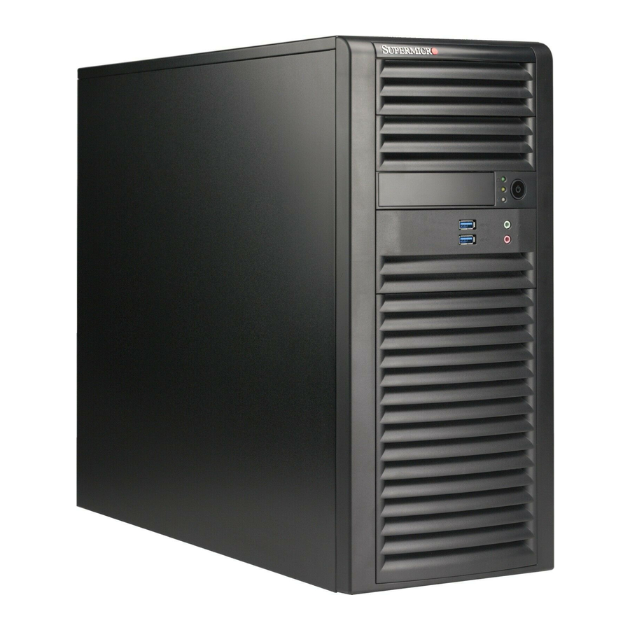
uper orkstation 5038A-I User's Manual Removing the Power Cord Before performing any setup or maintenance on the chassis, use the following procedure to ensure that power has been removed disconnected from the system. Removing the Power Cord 1. Use the operating system to power down the system, following the on-screen prompts. - Page 69 Chapter 6: Advanced Chassis Setup Figure 6-1. Chassis Front View Main Power USB Ports Audio (2x USB 3.0) Microphone Four SATA Drive Bays (inside chassis)
-
Page 70: Front Control Panel
uper orkstation 5038A-I User's Manual Front Control Panel The front control panel must be connected to the JF1 connector on the motherboard to provide you with system status and alarm indications. A ribbon cable has bundled these wires together to simplify this connection. Connect the cable from JF1 on the motherboard (making sure the red wire plugs into pin 1) to the appropriate comnnector on the front control panel PCB (printed circuit board). -
Page 71: Removing The Chassis Side Covers
Caution: Except for short periods of time, do NOT operate the system without the cover in place. The chassis cover must be in place to allow for proper airflow and to prevent overheating. Additional warnings and cautions can be found on the Supermicro website at http:// www.supermicro.com/about/policies/safety_information.cfm. -
Page 72: System Fans
5. Lift the fan up and out of the chassis. Installing a New Fan 1. Replace the failed fan with an identical one (available from Supermicro) 2. Secur the fan to the bracket with four screws and secure the bracket to the chassis with two screws. - Page 73 Chapter 6: Advanced Chassis Setup Figure 6-4. Removing a Chassis Fan (optional)
-
Page 74: Drive Installation
uper orkstation 5038A-I User's Manual Drive Installation A total of four SATA drives may be housed in the SC732D3-903B chassis. Remove the side panel of the chassis to access these drives as described in Section 6-4. Rotating the Hard Drive Cage 1. - Page 75 8. Insert the new hard drive into the hard drive carrier. Figure 6-7. Removing the 3.5" Hard Drive from the Hard Drive Carrier Note: Enterprise level hard disk drives are recommended for use in Supermicro chassis and servers. For information on recommended HDDs, visit the Supermicro Web site...
- Page 76 uper orkstation 5038A-I User's Manual Figure 6-8. Installing the Hard Drive Carrier into the Hard Drive Cage Optional Screw 9. Insert the hard drive carrier into the hard drive cage, sliding it towards the back of the the hard drive cage until it clicks into a locked position. 10.
-
Page 77: Removing And Installing Optional 2.5" Hard Drives
Chapter 6: Advanced Chassis Setup Removing and Installing Optional 2.5" Hard Drives Figure 6-9. Removing the 2.5" Hard Drives Thumb Screw The 5038A-I must be powered-down before hard drives can be removed. Removing and Installing 2.5" Hard Drives 1. Disconnect the chassis from any power source. 2. - Page 78 10. Connect the related cables to the hard drive Warning: Only enterprise level HDDs are recommended for use in this chassis. Ad- ditional warnings and cautions can be found on the Supermicro website at http://www. supermicro.com/about/policies/safety_information.cfm.
-
Page 79: Power Supply
Chapter 6: Advanced Chassis Setup Power Supply The 5038A-I includes a 900 watt power supply. In the unlikely event that it becomes necessary to replace the power supply, follow the instructions below. Figure 6-11. Removing the Power Supply Power Supply Changing the Power Supply 1. - Page 80 uper orkstation 5038A-I User's Manual Notes 6-14...
-
Page 81: Chapter 7 Bios
Chapter 7: BIOS Chapter 7 BIOS Introduction This chapter describes the AMI BIOS Setup Utility for the X10SRA/X10SRA-F motherboard. The ROM BIOS is stored in a Flash EEPROM and can be easily updated. This chapter describes the basic navigation of the AMI BIOS Setup Utility setup screens. -
Page 82: How To Change The Configuration Data
uper orkstation 5038A-I User's Manual The AMI BIOS GUI Setup Utility uses a mouse pointer navigation system similar to standard graphical user interfaces. Hover and click an icon to select a section, click a down arrow to select from an options list. Except for the Home screen, you may press the <F1>... -
Page 83: How To Start The Setup Utility
Chapter 7: BIOS How to Start the Setup Utility Normally, the only visible Power-On Self-Test (POST) routine is the memory test. As the memory is being tested, press the <Delete> key to enter the main menu of the AMI BIOS GUI Setup Utility. From the Setup Home screen, you can access the other Setup Sections. - Page 84 uper orkstation 5038A-I User's Manual The Save and Load icon brings up a pop-up menu that enables the user to choose from different saving options at the end of the session: Restore Defaults To set this feature, select Restore Defaults from the Save & Load menu and click <OK>.
-
Page 85: Booting
Chapter 7: BIOS Booting The Booting icon brings up a pop-up menu that enables the user to choose the booting mode, location and order of priority: See Section 4-12 (Booting) for more information. -
Page 86: System Information
uper orkstation 5038A-I User's Manual System Information The System Information Screen displays the motherboard's configuration. Motherboard The following information are displayed in this section: • Motherboard Model Name - X10SRA (-F). • BIOS Version - this item displays the BIOS version number. •... -
Page 87: Processor (Cpu)
Chapter 7: BIOS Processor (CPU) Information The following information are be displayed in this section: • Type and Speed of CPU - indicates the brand, model name, model number of the CPU and it's rated clock speed. • CPU Signature - displays the unique signature embedded in the CPU. •... - Page 88 uper orkstation 5038A-I User's Manual Performance Hyper-threading [ALL] Select Enabled to support Intel Hyper-threading Technology to enhance CPU per- formance. The options are Enabled and Disabled. Execute-Disable Bit Capability (Available if supported by the OS & the CPU) Select Enabled to enable the Execute-Disable Bit which will allow the processor to designate areas in the system memory where an application code can execute and where it cannot, thus preventing a worm or a virus from flooding illegal codes to overwhelm the processor or damage the system during an attack.
- Page 89 Chapter 7: BIOS Enable SMX Select Enable to activate SMX speed technology. The options are Enabled and Disabled. PPIN Control Select Enable to unlock the PPIN control. The options are Enabled and Disabled. Hardware Prefetcher (Available when supported by the CPU) If set to Enabled, the hardware prefetcher will prefetch streams of data and instruc- tions from the main memory to the L2 cache to improve CPU performance.
- Page 90 uper orkstation 5038A-I User's Manual Power Management Power Technology Select Energy Efficiency to support power-saving mode. Select Custom to custom- ize system power settings. Select Disabled to disable power-saving settings. The options are Disable, Energy Efficiency, and Custom. If the above is set to 'Custom' the following options are displayed: EIST EIST (Enhanced Intel SpeedStep Technology) allows the system to automatically adjust processor voltage and core frequency in an effort to reduce power consump-...
- Page 91 Chapter 7: BIOS P-STATE Coordination This feature selects the type of coordination for the P-State of the processor. P-State is a processor operational state that reduces the processor's voltage and frequency. This makes the processor more energy efficient, resulting in further energy gains. The options are HW_ALL, SW_ALL and SW-ANY.
-
Page 92: Chipset
uper orkstation 5038A-I User's Manual Chipset Set all options for the Chipset in this section. System Agent The following will be displayed: • System Agent Bridge Name - this displays the System Agent bridge name. • System Agent RC Version - indicates the System Agent RC version. •... - Page 93 Chapter 7: BIOS Relaxed Ordering Select Enable to enable Relaxed Ordering support which will allow certain transac- tions to violate the strict-ordering rules of PCI bus for a transaction to be completed prior to other transactions that have already been enqueued. The options are Dis- able and Enable.
- Page 94 uper orkstation 5038A-I User's Manual PCH I/O The following will be displayed: • PCH Name - this displays the chipset name. • PCH RC Version - indicates the PCH RC version. • PCH Stepping - this item displays the PCH stepping.. Azalia (HD Audio) This item controls the detection of the Azalia (HD Audio) device.
- Page 95 Chapter 7: BIOS On Board Chip Onboard USB Controller (USB 14/15) This feature Enables or Disables the USB controller for USB ports 14/15. The op- tions are Disabled and Enabled. Onboard USB Controller (USB 16/17) This feature Enables or Disables the USB controller for USB ports 16/17. The op- tions are Disabled and Enabled.
-
Page 96: Memory
uper orkstation 5038A-I User's Manual Memory Set all options for the System Memory in this section. Memory Information This item information on the memory modules installed on the motherboard. • DIMMA1~DIMMD2 - this item displays the type of memory that are detected for each memory slot. - Page 97 Chapter 7: BIOS Memory Configuration Enforce POR Select Enable to enforce POR restrictions on DDR4 frequency and voltage programming. The options are Enabled and Disabled. Memory Frequency Use this feature to set the maximum memory frequency for onboard memory modules. The options are Auto, 1333, 1400, 1600, 1800, 1867, 2000, 2133, 2200, 2400, 2600, and 2667.
-
Page 98: 7-7 Event Logs
uper orkstation 5038A-I User's Manual Set Throttling Mode Use this feature to activate Closed Loop Thermal Throttling (CLTT), which uses the DIMM memory temperature as input to make adjustments to the throttling based on variations in system's fan speed. The options are Disabled, and CLTT. A7 Mode Select Enabled to support the A7 (Addressing) mode to improve memory per- formance. - Page 99 Chapter 7: BIOS Memory Corrected Error Enabling (Available when the item above-Runtime Error Logging Support is set to Enable) Select Enabled for the BIOS to correct a memory error if it is correctable. The op- tions are Enabled and Disabled. Memory Correctable Error Threshold Use this item to enter the threshold value for correctable memory errors.
-
Page 100: 7-8 Management
uper orkstation 5038A-I User's Manual METW (Multiple Event Count Time Window) This item is used to determine how long (in minutes) should the multiple event counter wait before generating a new event log. Enter a number between 0 to 99. The default setting is 60. - Page 101 Chapter 7: BIOS Console Redirection COM 1 Enable Console Redirection Select Enabled to enable COM Port 1 Console Redirection, which will allow a client machine to be connected to a host machine at a remote site for networking. The options are Disabled and Enabled. *If the item above set to Enabled, the following items will become available for configuration: Console Redirection Settings...
- Page 102 uper orkstation 5038A-I User's Manual Data Bits Use this feature to set the data transmission size for Console Redirection. The options are 7 (Bits) and 8 (Bits). Parity A parity bit can be sent along with regular data bits to detect data transmission errors.
- Page 103 Chapter 7: BIOS Putty KeyPad This feature selects Function Keys and KeyPad settings for Putty, which is a terminal emulator designed for the Windows OS. The options are VT100, LINUX, XTERMR6, SCO, ESCN, and VT400. Redirection After BIOS Post Use this feature to enable or disable legacy Console Redirection after BIOS POST.
- Page 104 uper orkstation 5038A-I User's Manual Parity A parity bit can be sent along with regular data bits to detect data transmission errors. Select Even if the parity bit is set to 0, and the number of 1's in data bits is even.
- Page 105 Chapter 7: BIOS Redirection After BIOS Post Use this feature to enable or disable legacy Console Redirection after BIOS POST (Power-On Self-Test). When this feature is set to Bootloader, legacy Console Redirection is disabled before booting the OS. When this feature is set to Always Enable, legacy Console Redirection remains enabled upon OS boot.
- Page 106 uper orkstation 5038A-I User's Manual Flow Control Use this item to set the flow control for Console Redirection to prevent data loss caused by buffer overflow. Send a "Stop" signal to stop data-sending when the receiving buffer is full. Send a "Start" signal to start data-sending when the receiving buffer is empty.
-
Page 107: 7-9 Input/Output
Chapter 7: BIOS 7-9 Input/Output Set all options for the I/O in this section. SATA SATA Controller This item enables or disables the onboard SATA controller supported by the Intel PCH chip. The options are Enabled and Disabled. Configure SATA as Select IDE to configure a SATA drive specified by the user as an IDE drive. - Page 108 uper orkstation 5038A-I User's Manual SATA Port 0 ~ SATA Port 5 This item displays the information detected on the installed SATA drive on the particular SATA port. • Model number of drive and capacity Port 0 ~ Port 5 Spin Up Device On an edge detect from 0 to 1, set this item to allow the PCH to initialize the device.
- Page 109 Chapter 7: BIOS • Model number of drive and capacity Port 0 ~ Port 5 Spin Up Device On an edge detect from 0 to 1, set this item to allow the PCH to start a COMRE- SET initialization to the device. The options are Enabled and Disabled. Port 0 ~ Port 5 SATA Device Type Use this item to specify if the SATA port specified by the user should be con- nected to a Solid State drive or a Hard Disk Drive.
- Page 110 uper orkstation 5038A-I User's Manual Support Aggressive Link Power Management When this item is set to Enabled, the sSATA AHCI controller manages the power usage of the sSATA link. The controller will put the link to a low power state when the I/O is inactive for an extended period of time, and the power state will return to normal when the I/O becomes active.
- Page 111 Chapter 7: BIOS Support Aggressive Link Power Management When this item is set to Enabled, the SATA AHCI controller manages the power usage of the SATA link. The controller will put the link to a low power state when the I/O is inactive for an extended period of time, and the power state will return to normal when the I/O becomes active.
- Page 112 uper orkstation 5038A-I User's Manual PCIe/PCI/PnP Above 4G Decoding (Available if the system supports 64-bit PCI decoding) Select Enabled to decode a PCI device that supports 64-bit in the space above 4G Address. The options are Enabled and Disabled. SR-IOV Support Single Root I/O Virtualization (SR-IOV) is a specification that allows a PCIe device to appear as multiple physical devices to the system.
- Page 113 Chapter 7: BIOS SLOT2 and SLOT4 Selection This option allows the user to select between activating Slot2 and Slot4 both at x8 OR, Slot4 at x16. The options are Slot2(x8) and Slot4(x), or Slot4(x16). CPU SLOT1 PCI-E 3.0 X8 (IN X16) - GEN X, CPU SLOT2 PCI-E 3.0 X8 (IN X16) - GEN X, CPU SLOT4 PCI-E 3.0 X8 (IN X16) - GEN X, CPU SLOT6 PCI-E 3.0 X16 - GEN X...
- Page 114 uper orkstation 5038A-I User's Manual VGA Priority Use this item to select the graphics device to be used as the primary video display for system boot. The options are Auto (for the X10SRA), Onboard VGA (for the X10SRA-F), CPU SLOT1 PCI-E 3.0 X8 (IN X16), CPU SLOT2 PCI-E 3.0 X8 (IN X16), PCH SLOT3 PCI-E 2.0 X1 (IN X4), CPU SLOT4 PCI-E 3.0 X8 (IN X16), PCH SLOT5 PCI-E 2.0 X1 (IN X4), and CPU SLOT6 PCI-E 3.0 X16.
- Page 115 Chapter 7: BIOS EHCI Hand-Off This item is for operating systems that do not support Enhanced Host Controller Interface (EHCI) hand-off. When this item is enabled, EHCI ownership change will be claimed by the EHCI driver. The settings are Enabled and Disabled. XHCI Mode This feature handles the operation mode for the XHCI (Extensible Host Controller Interface) controller.
-
Page 116: 7-10 Security
uper orkstation 5038A-I User's Manual Serial Port 1 Configuration This item will Enable or Disable Serial Port 1 (COM1). Place a tick mark on the box to enable Serial Port 1. The default is Enabled. Current Config (IRQ) This item displays the current IRQ setting for Serial Port 1 (COM1). Change (IRQ) Settings This item configures the IRQ setting for Serial Port 1 (COM1). - Page 117 Chapter 7: BIOS Password This menu allows the user to configure the following security settings for the system. • If the Administrator password is defined ONLY - this controls access to the BIOS setup ONLY. • If the User's password is defined ONLY - this password will need to be entered upon each system boot, and will also have Administrator rights in the setup.
- Page 118 uper orkstation 5038A-I User's Manual Secure Boot The following items will be displayed: • System Mode - indicates the current system mode. • Secure Boot - this item indicates if Secure Boot is activated or not. • Vendor Keys - indicates if Vendor Keys are activated or not. Secure Boot Select Enabled for Secure Boot flow control.
- Page 119 Chapter 7: BIOS Default Key Provision This item will load the default key provision. The options are Enabled and Disabled. Enroll All Factory Default Keys This item will install the factory default secure variables. The options are Yes and Save All Secure Boot Variables This item will save all the revised secure boot variables.
- Page 120 uper orkstation 5038A-I User's Manual Append KEK This item uploads and adds a Key Exchange Key into the Key Management. You may insert a factory default key or load from a file. When prompted, select "Yes" to load Factory Defaults or "No' to load from a file. Authorized Signatures This item displays the current Authorized Signatures status.
-
Page 121: 7-11 Booting
Chapter 7: BIOS d. EFI SERT SHA256 (bin) 2) EFI Time Based Authenticated Variable When prompted, select "Yes" to load Factory Defaults or "No' to load from a file. Append DBX This item uploads and adds an Forbidden Signature into the Key Management. You may insert a factory default key or load from a file. - Page 122 uper orkstation 5038A-I User's Manual The different boot settings and options for the motherboard are in this section. Boot Device Settings Quiet Boot This option sets the state to which the system buzzer is configured when booting. The default is Enabled, the buzzer is silent. Boot Mode Select Use this item to select the type of device to be used for system boot.
- Page 123 Chapter 7: BIOS • Dual Boot Order #15 • HDD Special Boot Instance • CD/DVD Special Boot Instance • USB Hard Disk Special Boot Instance • USB CD/DVD Special Boot Instance • USB Key Special Boot Instance • USB Floppy Special Boot Instance •...
- Page 124 uper orkstation 5038A-I User's Manual BIOS Features Bootup Numlock State This option sets the state to which the NumLock key is configured when booting. The default is On. AddOn ROM Display Mode This item sets the display mode for the Option ROM. Select Keep Current to use the current AddOn ROM Display setting.
- Page 125 Chapter 7: BIOS Retry Boot Select Enabled to force the system to reboot when system fails to boot. The op- tions are Disabled and Enabled. Watch Dog Function If enabled, the Watch Dog timer will allow the system to reboot when it is unre- sponsive for more than 5 minutes.
-
Page 126: Appendix A Bios Error Beep Codes
Appendix A: POST Error Beep Codes Appendix A BIOS Error Beep Codes During the POST (Power-On Self-Test) routines, which are performed each time the system is powered on, errors may occur. Non-fatal errors are those which, in most cases, allow the system to continue with bootup. - Page 127 uper orkstation 5038A-I User's Manual Notes...
-
Page 128: Appendix B Dual Boot Block
Appendix B: Dual Boot Block Appendix B Dual Boot Block B-1 Introduction This motherboard supports the Dual Boot Block feature, which is a last-ditch mechanism to recover the BIOS boot block. This section provides an introduction to the feature. BIOS Boot Block A BIOS boot block is the minimum BIOS loader required to enable necessary hardware components for the BIOS crisis recovery flash that will update the main BIOS block. - Page 129 uper orkstation 5038A-I User's Manual B-2 Steps to Reboot the System by switch JBR1 1. Power down the system. 2. On switch JBR1 slide switch to ON, and power on the system. 3. Follow the BIOS recovery SOP listed in the previous chapter (Appendix C). 4.
-
Page 130: Appendix C System Specifications
Appendix C: System Specifications Appendix C System Specifications Processors Supports single Intel Xeon E5-2600/1600 v3/v4 family or Intel Core™ i7 Series processor in an LGA2011-3 socket Note: Please refer to our web site for a complete listing of supported processors. Chipset Intel C612 BIOS... - Page 131 uper orkstation 5038A-I User's Manual Motherboard X10SRA Dimensions: 12" x 9.6" (304.8 mm x 243.84 mm) Chassis SC732D3-903B Form Factor: Mid-tower Dimensions (WxHxD) 7.6 x 16.7 x 20.68 in. (193 x 424 x 525.3 mm) Weight Gross (Bare Bone): 39 lbs. (17.7 kg.) System Cooling One (1) 12-cm low-noise exhaust fan One (1) active CPU heatsink (optional)
- Page 132 Appendix C: System Specifications Regulatory Compliance Electromagnetic Emissions: FCC Class B, EN 55032 Class B, EN 61000-3-2/-3- 3, CISPR 32 Class B Electromagnetic Immunity: EN 55024/CISPR 24, (EN 61000-4-2, EN 61000-4-3, EN 61000-4-4, EN 61000-4-5, EN 61000-4-6, EN 61000-4-8, EN 61000-4-11) Safety: CSA/EN/IEC/UL 60950-1 Compliant, UL or CSA Listed (USA and Canada), CE Marking (Europe) Other: VCCI-CISPR 32 and AS/NZS CISPR 32...
- Page 133 5038A-I User's Manual (continued from front) The products sold by Supermicro are not intended for and will not be used in life support systems, medical equipment, nuclear facilities or systems, aircraft, aircraft devices, aircraft/emergency com- munication devices or other critical systems whose failure to perform be reasonably expected to result in significant injury or loss of life or catastrophic property damage.
Need help?
Do you have a question about the SuperWorkstation 5038A-I and is the answer not in the manual?
Questions and answers