Table of Contents
Advertisement
Quick Links
Advertisement
Table of Contents

Related Manuals for Supermicro 5039AD-I


Summary of Contents for Supermicro 5039AD-I
- Page 1 High Performance Desktop 5039AD-I USER’S MANUAL Revision 1.0...
- Page 2 State of California, USA. The State of California, County of Santa Clara shall be the exclusive venue for the resolution of any such disputes. Supermicro's total liability for all claims will not exceed the price paid for the hardware product.
-
Page 3: About This Manual
5039AD-I. Installation and maintenance should be performed by experienced technicians only. Please refer to the 5039AD-I server specifications page on our website for updates on supported memory, processors, and operating systems (http://www.supermicro.com). -
Page 4: Table Of Contents
Preface Contents Chapter 1 Introduction 1.1 Overview ..........................7 1.2 Unpacking the System ......................7 1.3 System Features ........................8 1.4 Server Chassis Features ......................9 Control Panel ........................9 Front and Rear Features....................10 1.5 Motherboard Layout ......................11 Quick Reference Table ......................12 Chapter 2 Workstation Setup 2.1 Overview ..........................14 2.2 Unpacking the System .......................14 2.3 Workstation Precautions .....................14... - Page 5 High Performance Desktop 5039AD-I User's Manual Air Flow ..........................33 Dust Filters ........................33 Power Supply ........................34 Chapter 4 Motherboard Connections 4.1 Power Connections ......................35 4.2 Headers and Connectors ....................36 Control Panel ........................40 4.3 Ports ...........................43 4.4 Jumpers ..........................45 Explanation of Jumpers.....................45 4.5 LED Indicators ........................48...
-
Page 6: Contacting Supermicro
High Performance Desktop 5039AD-I User's Manual Contacting Supermicro Headquarters Address: Super Micro Computer, Inc. 980 Rock Ave. San Jose, CA 95131 U.S.A. Tel: +1 (408) 503-8000 Fax: +1 (408) 503-8008 Email: marketing@supermicro.com (General Information) support@supermicro.com (Technical Support) Website: www.supermicro.com Europe Address: Super Micro Computer B.V. -
Page 7: Chapter 1 Introduction
CBL-SAST-0957 1.2 Unpacking the System Inspect the box that the 5039AD-I was shipped in and note if it was damaged in any way. If any equipment appears damaged, file a damage claim with the carrier who delivered it. Decide on a suitable location for the system. It should be situated in a clean, dust-free area that is well-ventilated. -
Page 8: System Features
High Performance Desktop 5039AD-I User's Manual 1.3 System Features The following table provides an overview of the main features of the 5039AD-I. Refer to Appendix C for additional specifications. System Features Motherboard C9X299-PGF Chassis GS5A-753K Intel® Core™ X-series processor Socket Type... -
Page 9: Server Chassis Features
Chapter 1: Introduction 1.4 Server Chassis Features Control Panel The switches and LEDs located on the control panel are described below. The control panel is located on the front end of the chassis. See Chapter 4 for details on the control panel connections. -
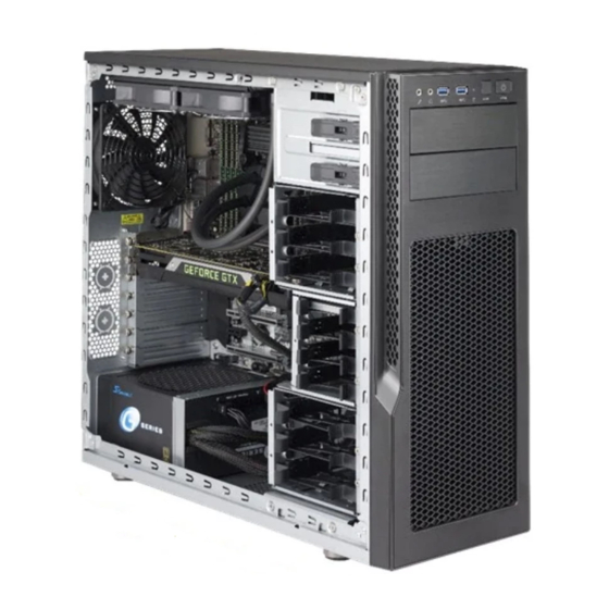
Page 10: Front And Rear Features
High Performance Desktop 5039AD-I User's Manual Front and Rear Features The GS5A-753K is a mid-tower chassis. See the illustration below for the features included on the front and rear of the chassis. USB 3.1 USB 3.1 TYPE C SPDIF OUT... -
Page 11: Motherboard Layout
Chapter 1: Introduction 1.5 Motherboard Layout Below is a layout of the C9X299-PGF with jumper, connector, and LED locations shown. See the table on the following page for descriptions. For detailed descriptions, pinout information, and jumper settings, refer to Chapter 4. LAN2 SLOT5 SLOT7... -
Page 12: Quick Reference Table
High Performance Desktop 5039AD-I User's Manual Quick Reference Table Jumper Description Default Setting CLEAR CMOS CMOS clear switch Push Button Switch JBT1 Clear CMOS Short pads to clear CMOS JPAC1 Audio enable Pins 1-2 (Enabled) JPG1 VGA Enable/Disable Pins 1-2 (Enabled) - Page 13 Chapter 1: Introduction Connector Description USB6/7, 8/9 Back panel USB 3.1 ports (USB8: Type A; USB9: Type C) USB16/17 Front access USB 3.0 Headers Back panel VGA port Description Status LED1 Status code LED Digital readout* LED6903 M.2 connector 2 active LED Solid Green: M.2 device active LED6904 M.2 connector 1 active LED...
-
Page 14: Chapter 2 Workstation Setup
High Performance Desktop 5039AD-I User's Manual Chapter 2 Workstation Setup 2.1 Overview This chapter provides advice and instructions for setting up your workstation. If your system is not already fully integrated with processors, system memory, etc., refer to Chapter 4 for details on installing those components. -
Page 15: Installing The Gpu
Chapter 2: Server Installation 2.4 Installing the GPU A compatible graphics processing unit (GPU) must be installed into one of the PCI-e expansion slots. If the 2.5" HDD cage is installed, the maximum supported GPU size is 320mm. If the 2.5"... -
Page 16: Chapter 3 Component Installation And Maintenance
3. Disconnect the power cord(s) from the power supply module(s). 3.2 Accessing the System The 5039AD-I has two removable side covers. Except for short periods of time, do not operate the system without the cover in place. The chassis cover allows proper cooling airflow. -
Page 17: Front Bezel
Chapter 3: Component Installation and Maintenance Figure 3-1. Removing the Side Chassis Covers Front Bezel Remove the front bezel by pulling off the bottom first. Generally, this is only necessary when replacing the front fans. Figure 3-2. Removing the Front Bezel... -
Page 18: Motherboard Components
CPU socket cap is in place and none of the socket pins are bent. Otherwise, contact your retailer immediately. • Refer to the Supermicro website for updates on CPU support. Installing the Processor Begin by removing power from the system as described in Section 3.1 and removing the chassis cover as described in Section 3.2. - Page 19 Chapter 3: Component Installation and Maintenance Press down on Load Lever labeled 'Open 1st'. Pull lever away from Press on Load Lever the socket 'Close 1st' Gently push down to pop the load plate open. Figure 3-4. Removing the Warning Cap...
- Page 20 High Performance Desktop 5039AD-I User's Manual 5. Use your thumb and index finger to hold the CPU by its edges. Align the CPU keys (semi-circle cutouts) against the socket keys. Socket Keys CPU Keys Figure 3-5. Aligning CPU Keys with Socket Keys 6.
-
Page 21: Installing The Cpu Heatsink
Chapter 3: Component Installation and Maintenance Installing the CPU Heatsink Begin by removing power from the system as described in Section 3.1 and removing the chassis cover as described in Section 3.2. 1. Apply the proper amount of thermal grease to the heatsink. 2. -
Page 22: Removing The Cpu Heatsink
High Performance Desktop 5039AD-I User's Manual Removing the CPU Heatsink Warning: Only remove the heatsink if necessary. Begin by removing power from the system as described in Section 3.1 and removing the chassis cover as described in Section 3.2. 1. Loosen the heatsink screws in the order shown in Figure 3-7. -
Page 23: Memory
Chapter 3: Component Installation and Maintenance Memory Memory Support The C9X299-PGF supports up to 128GB of unbuffered, non-ECC, DDR4 memory in eight slots. Refer to the diagram below for additional memory information. Core™ X-Series One DIMM (6-core or Two DIMM above) Four DIMM Six DIMM... -
Page 24: Dimm Installation/Removal
Reverse the steps above to remove the DIMM modules from the motherboard. Press both notches straight down into the memory slot. Notches Release Tab Figure 3-9. Installing DIMMs Note: Visit the product page on the Supermicro website for possible updates to memory support (www.supermicro.com). -
Page 25: Pci-E Expansion Cards
Chapter 3: Component Installation and Maintenance PCI-e Expansion Cards The 5039AD-I can accommodate up to seven PCI-e expansion cards. Install your graphics card into a PCI-e expansion slot. Installing an Expansion Card Begin by removing power from the system as described in Section 3.1 and removing the cover as described in Section 3.2. -
Page 26: Chassis Components
High Performance Desktop 5039AD-I User's Manual 3.4 Chassis Components Hard Drives Your system might ship with hard drives installed. The chassis has two 5.25" drive bays, four 2.5" drive bays, and six bays that can hold 3.5" or 2.5" drives. - Page 27 Chapter 3: Component Installation and Maintenance Removing a Hot-Swap Drive Carrier 1. Push the release button on the carrier. 2. Swing the handle fully out. 3. Grasp the handle and use it to pull the drive carrier out of its bay. Installing a Storage Device in the 5.25"...
- Page 28 High Performance Desktop 5039AD-I User's Manual Figure 3-13. Storage Device Configurations for 5.25" Bays Installing Drives into a Removable Cage You can install up to four 2.5" drives in the dedicated center cage. Also, you can install up to three 2.5" or 3.5" drives into each combination cage (upper and lower).
- Page 29 Chapter 3: Component Installation and Maintenance Figure 3-14. Installing Drives and Mounting Brackets into the Cage Figure 3-15. Mounting Tray for 3.5" Drive...
- Page 30 High Performance Desktop 5039AD-I User's Manual Figure 3-16. Mounting Tray for 2.5" Drive...
-
Page 31: System Cooling
Chapter 3: Component Installation and Maintenance System Cooling Three 120 mm fans provide the cooling for the system (two in the front, one in the rear). Additionally, the following fan mount configurations are supported: • Front fans can be replaced with 140 mm fans. •... - Page 32 High Performance Desktop 5039AD-I User's Manual Figure 3-18. All Possible Fan Placements...
-
Page 33: Water Cooled Heatsink
Chapter 3: Component Installation and Maintenance Water Cooled Heatsink The chassis supports a water cooled CPU heatsink. A 120 mm radiator can be placed over the rear fan. A 240 mm radiator can be place under the top of the chassis. Consult your water cooling kit instructions for installation. -
Page 34: Power Supply
The top and bottom magnetic filters can also be removed for cleaning. Power Supply The 5039AD-I has a 750 watt power supply module. Mount the power supply on the rear floor of the chassis. The power supply can be mounted with the fan facing either up or down. -
Page 35: Chapter 4 Motherboard Connections
Chapter 4: Motherboard Connections Chapter 4 Motherboard Connections This section describes the connections on the motherboard and provides pinout definitions. Depending on how the system is configured, not all connections are required. The LEDs on the motherboard are also described here. A motherboard layout indicating component locations can be found in Chapter 1. -
Page 36: Headers And Connectors
High Performance Desktop 5039AD-I User's Manual 8-Pin Power Connector JPW2 is an 8-pin 12V DC power input for the processors, which must be connected to the power supply. Refer to the table below for pin definitions. 8-pin Power Pin Definitions (JPW2) -
Page 37: Chassis Intrusion
A Trusted Platform Module (TPM)/Port 80 header is located at JTPM1 to provide TPM support and Port 80 connection. Use this header to enhance system performance and data security. Refer to the table below for pin definitions. The following document provides information about the TPM: http://www.supermicro.com/manuals/other/TPM.pdf. Trusted Platform Module Header Pin Definitions... - Page 38 High Performance Desktop 5039AD-I User's Manual External Speaker Pins 1-4 of JD1 are for the speaker, and pins 3-4 are for the buzzer. The speaker connector pins (1-4) are used with an external speaker. If you wish to use the onboard speaker, close pins 1-4 with a cap.
- Page 39 Parallel ATA. Note: For more information on the SATA HostRAID configuration, please refer to the Intel SATA HostRAID user's guide posted on our website at http://www.supermicro.com. SATA 2.0/3.0 Connectors Pin Definitions Pin#...
-
Page 40: Control Panel
High Performance Desktop 5039AD-I User's Manual Control Panel JF1 contains header pins for various control panel connections. Refer to the figure below for the pin locations and definitions of the control panel buttons and LED indicators. All JF1 wires have been bundled into a single cable to simplify this connection. Verify that the red wire plugs into pin 1 as marked on the motherboard. - Page 41 Chapter 4: Motherboard Connections Reset Button The Reset Button connection is located on pins 3 and 4 of JF1. Attach it to a hardware reset switch on the computer case to reset the system. Refer to the table below for pin definitions. Reset Button Pin Definitions (JF1) Pins...
- Page 42 High Performance Desktop 5039AD-I User's Manual NIC1/NIC2 (LAN1/LAN2 or LAN3/LAN4) The Network Interface Controller (NIC) LED connection for LAN port 1 is located on pins 11 and 12 of JF1, while LAN port 2 is on pins 9 and 10. Attach the NIC LED cables here to display network activity.
-
Page 43: Ports
Chapter 4: Motherboard Connections 4.3 Ports Figure 4-2. Rear I/O Ports Rear I/O Ports Description Description Description PS/2 Keyboard/Mouse USB 3.1 Port 7 Surround Out USB 3.0 Ports 4/5 1GbE LAN Port 2 (IPMI) S/PDIF Out VGA Port USB 3.1 Port 8 (Type A) Line In 5GbE LAN Port 1 USB 3.1 Port 9 (Type C) - Page 44 High Performance Desktop 5039AD-I User's Manual Universal Serial Bus (USB) Ports There are two USB 3.0 ports (USB4/5) and four USB 3.1 ports (USB6/7, USB8: Type A, USB9: Type C) located on the I/O back panel. The motherboard also has two front accessible USB 2.0 headers (USB0/1, USB2/3) and one front accessible USB 3.0 header (USB16/17).
-
Page 45: Jumpers
Chapter 4: Motherboard Connections 4.4 Jumpers Explanation of Jumpers To modify the operation of the motherboard, jumpers are used to choose between optional settings. Jumpers create shorts between two pins to change the function associated with it. Pin 1 is identified with a square solder pad on the printed circuit board. Refer to the motherboard layout diagram in Section 1.5 for jumper locations. - Page 46 High Performance Desktop 5039AD-I User's Manual Watch Dog Watch Dog (JWD1) is a system monitor that can reboot the system when a software application hangs. Close pins 1-2 to reset the system if an application hangs. Close pins 2-3 to generate a non-maskable interrupt (NMI) signal for the application that hangs. Refer to the table below for jumper settings.
- Page 47 Chapter 4: Motherboard Connections Audio Enable JPAC1 allows you to enable or disable the onboard audio support. The default position is on pins 1-2 to enable onboard audio connections. Refer the table on the right for jumper settings. Audio Enable/Disable Jumper Settings Jumper Setting Definition...
-
Page 48: Led Indicators
High Performance Desktop 5039AD-I User's Manual 4.5 LED Indicators LAN LEDs Two LAN ports (LAN 1 ~ LAN 2) are located on the I/O back panel of the motherboard. Each Ethernet LAN port has two LEDs. The green LED indicates activity, while the other Link LED may be green, amber, or off to indicate the speed of the connection. - Page 49 Chapter 4: Motherboard Connections Onboard Power LED The Onboard Power LED is located at LEDPWR on the motherboard. When this LED is on, MAC CODE the system is on. Be sure to turn off the system and unplug the power cord before removing or installing components.
-
Page 50: Chapter 5 Software
High Performance Desktop 5039AD-I User's Manual Chapter 5 Software After the hardware has been installed, install the Operating System (OS), configure RAID settings, and install the drivers. Necessary drivers and utilities can be found at ftp://ftp. supermicro.com/driver. 5.1 OS Installation You must first configure RAID settings (if using RAID) before you install the Windows OS and the software drivers. -
Page 51: Driver Installation
Chapter 5: Software 5.2 Driver Installation The Supermicro FTP site contains drivers and utilities for your system at ftp://ftp.supermicro. com. Some of these must be installed, such as the chipset driver. After accessing the FTP site, navigate to the CDR_Images directory and locate the ISO file for your motherboard. -
Page 52: Superdoctor ® 5
5.3 SuperDoctor ® Supermicro SuperDoctor 5 is a program that functions in a command line or web-based interface for Windows and Linux operating systems. The program monitors system health information such as CPU temperature, system voltages, system power consumption, and fan speed, and provides alerts via email or Simple Network Management Protocol (SNMP). -
Page 53: Ipmi
The C9X299-PGF supports the Intelligent Platform Management Interface (IPMI). IPMI is used to provide remote access, monitoring, and management. There are several BIOS settings that are related to IPMI. For general documentation and information on IPMI, visit our website at: http://www.supermicro.com/products/nfo/IPMI.cfm. -
Page 54: Chapter 6 Bios
High Performance Desktop 5039AD-I User's Manual Chapter 6 BIOS 6.1 Introduction This chapter describes the AMIBIOS™ Setup utility for the motherboard. The BIOS is stored on a chip and can be easily upgraded using a flash program. Note: Due to periodic changes to the BIOS, some settings may have been added or deleted and might not yet be recorded in this manual. -
Page 55: Changing Between Ez Mode And Advanced Mode
Chapter 6: BIOS Changing Between EZ Mode and Advanced Mode Above the basic motherboard information and the clock is the EZ Mode/Advanced Mode button. When in EZ Mode, Serial ATA Port 0~5 information will be displayed. When in Advanced Mode, all following configuration menus and their contents become available. 6.2 Overclocking CPU Configuration ... - Page 56 High Performance Desktop 5039AD-I User's Manual Per Core Mode When enabled, this feature unlocks 'Core Voltage Mode', 'Core Extra Turbo Voltage', and 'Core Voltage Offset' configuration for Core-0~9. The options are Disabled or Enabled. Core-0~9 Max Ratio This feature overrides the Core Max Ratio on a per-core basis. Settings change automatically, unless 'Load SMC CPU OC Setting' feature is set to manual.
- Page 57 Chapter 6: BIOS Offset Prefix This feature controls the offset value prefix. The options are positive (+) or negative (-). Adjust Pll This feature sends the mailbox command to adjust the Pll for higher-HCLK ratio combination. The options are Disabled or Enabled. Change PllTrim Value Enter a value to change the Pll value to.
- Page 58 High Performance Desktop 5039AD-I User's Manual Energy Efficient Turbo Select Enabled to activate Energy Efficient Turbo. This feature will opportunistically lower the turbo frequency to increase efficiency. We recommend to leave this enabled and disable only in overclocking situations where the turbo frequency must remain constant.
- Page 59 Chapter 6: BIOS Hardware PM State Control Hardware P-States This feature controls how P-states are selected. The 'Disable' option bases the choice on OS Request. The 'Native Mode'/'Native Mode with No Legacy Support' option bases the choice on OS guidance. The 'Out of Band Mode' option enables autonomous P-state selection.
- Page 60 High Performance Desktop 5039AD-I User's Manual CLR/Ring CLR Max OC Ratio This feature controls the maximum overclocking ratio for the CLR. The default is 0. CLR Min Ratio This feature sets the minimum ratio for the CLR. The default is 8.
- Page 61 Chapter 6: BIOS SVID VCCIO Voltage Override This feature overrides the VccIO input voltage, which affects the input voltage to the CPU. The default is 0. Load Line Calibration This feature controls the Load Line Calibration. The options are Disabled, Level 1, Level 2, Level 3, Level 4, Level 5, Level 6, Level 7, and Auto.
- Page 62 High Performance Desktop 5039AD-I User's Manual tRCD This feature selects the Row to Col Delay Range. Enter a number between 1-38. The default is 17. This feature selects the Ras Precharge Range. Enter a number 1-38. The default is 17.
- Page 63 Chapter 6: BIOS tREFI This feature configures the Maximum tREFI Time (Average Periodic Refresh Interval). Enter a numeric value. The default is 8320. tREFIx9 Enter a value for desired tREFIx9. The default is 73. Enter a value for desired tRC. The default is 50. 3rd timing: tWTR_L Enter a value for desired tWTR_L.
- Page 64 High Performance Desktop 5039AD-I User's Manual tWRDR Enter a value for desired tWRDR. The default is 1. tWRDD Enter a value for desired tWRDD. The default is 1. tRWSR Enter a value for desired tRWSR. The default is 5. tRRDS Enter a value for desired tRRDS.
- Page 65 Chapter 6: BIOS IOL (CHA DIMM1) Enter a value for desired IOL (CHA DIMM1). The default is 0. IOL (CHA DIMM2) Enter a value for desired IOL (CHA DIMM2). The default is 0. IOL (CHB DIMM1) Enter a value for desired IOL (CHB DIMM1). The default is 0. IOL (CHB DIMM2) Enter a value for desired IOL (CHB DIMM2).
- Page 66 High Performance Desktop 5039AD-I User's Manual Rcompresistors3 Enter a value for desired Rcompresistors3. The default is 100. DDR4 ODT Configuration CHA DIMM1 RTT_WR Enter a value for desired CHA DIMM1 RTT_WR. The options are Auto, Disabled, 60, 80, 120, 240, and Infinity.
- Page 67 Chapter 6: BIOS CHB DIMM2 RTT_WR Enter a value for desired CHB DIMM2 RTT_WR. The options are Auto, Disabled, 60, 80, 120, 240, and Infinity. CHB DIMM2 RTT_Prk Enter a value for desired CHB DIMM2 RTT_Prk. The options are Auto, Disabled, 60, 80, 120, 240, and Infinity.
- Page 68 High Performance Desktop 5039AD-I User's Manual CHD DIMM1 RTT_NOM Enter a value for desired CHD DIMM1 RTT_NOM. The options are Auto, Disabled, 60, 80, 120, 240, and Infinity. CHD DIMM2 RTT_WR Enter a value for desired CHD DIMM2 RTT_WR. The options are Auto, Disabled, 60, 80, 120, 240, and Infinity.
- Page 69 Chapter 6: BIOS Vcc ST SFR Vout voltage When the above feature is enabled, select a voltage option. The options are 1.000V, 1.071V, 1.140V, 1.209V, 1.279V, 1.348V, 1.417V, 1.476V, and 1.530V. Vcc SFR OC voltage override enable This feature overrides the Vcc SFR OC voltage. The options are Disabled or Enabled. Vcc SFR OC voltage When the above feature is enabled, select a voltage option.
-
Page 70: Cpu
High Performance Desktop 5039AD-I User's Manual 6.3 CPU Note: The following submenus only display when using Core™ i9 7980X/7900X or i7 7820X/7800X CPUs. Core™ i7 7740X and i5 7640X CPUs display different options. Processor Configuration Information (dependant on current hardware) is shown for the following features:... - Page 71 Chapter 6: BIOS Execute Disable Bit This feature enables Execute Disable Bit. When disabled, it forces the Execute Disable feature flag to always return 0. The options are Disabled or Enabled. Intel(VMX) Virtualization Technology This feature enables a VMM to utilize Vanderpool (virtualization) Technology hardware capabilities.
- Page 72 High Performance Desktop 5039AD-I User's Manual MMCFG Size This feature controls the MMCFG Size. The options are 64M, 128M, 256M, 512M, 1G, and 2G. MMIOHBase This feature controls the MMIO High Base. The options are 56T, 40T, 24T, 16T, 4T, and 1T.
-
Page 73: Memory
Chapter 6: BIOS Enhanced Halt State (C1E) This feature enables Enhanced Halt State (takes effect after reboot). The options are Disabled or Enabled. Package C State Control Package C State This feature controls the Package C State limit. The options are C0/C1 state, C2 state, C6(non Retention) state, C6(Retention) state, No Limit, and Auto. - Page 74 High Performance Desktop 5039AD-I User's Manual MC BGF threshold Enter a value for the HA to MC BGF threshold, which is used for scheduling MC request in bypass conditions. The default is 0. DLL Reset Test Enter a value for the amount of loops to execute RMT for during DLL reset tests. The default is 0.
-
Page 75: Advanced
Chapter 6: BIOS 6.5 Advanced PCH-FW Configuration This menu shows the following information: • ME Firmware Version • ME Firmware Mode • ME Firmware SKU • ME File System Integrity Value • ME Firmware Status 1 • ME Firmware Status 2 Me FW Image Re-Flash Use this feature to update the Management Engine firmware from an image in a USB flash drive attached to a USB port. -
Page 76: North Bridge
High Performance Desktop 5039AD-I User's Manual North Bridge IIO Configuration EV DFX Features This feature enables IIO DFX devices and other CPU devices like PMON. The options are Disabled or Enabled. Isoc Mode This feature controls Isoc mode support. The options are Disabled, Enabled, and Auto. - Page 77 Chapter 6: BIOS JNVME0~2 Link Speed This feature controls the link speed for this PCIe port. The options are Auto, Gen 1 (2.5 GT/s), Gen 2 (5GT/s), and Gen 3 (8 GT/s). PCI-E Port Max Payload Size This feature controls this PCIe port's maximum payload size. If possible set to 256B. The default is Auto.
-
Page 78: South Bridge
High Performance Desktop 5039AD-I User's Manual This feature enables Non-Isoch VT-d engine Coherency support. The options are Disabled or Enabled. Intel® VMD technology Intel® VMD for Volume Management Device on CPU Intel® VMD for Volume Management This feature enables Volume Management Device technology in this stack. The op- tions are Disabled or Enabled. -
Page 79: Trusted Computing
Chapter 6: BIOS Configure SATA as Use this feature to select the mode for the installed SATA drives. The options are AHCI or RAID. Aggressive Link Power Management Select enabled for the PCH to aggressively enter the link power state. The options are Disabled or Enabled. -
Page 80: Acpi Settings
High Performance Desktop 5039AD-I User's Manual The following Platform Configuration Register information will be displayed: • Active PCR banks: SHA-1,SHA256 • Available PCR banks: SHA-1,SHA256 *If the feature 'Security Device Support' is set to Enable, the following features will become... - Page 81 Chapter 6: BIOS High Precision Event Timer Select Enabled to activate the High Precision Event Timer (HPET) that produces periodic interrupts at a much higher frequency than a Real-time Clock (RTC) does in synchronizing multimedia streams, providing smooth playback and reducing the dependency on other timestamp calculation devices, such as an x86 RDTSC Instruction embedded in the CPU.
- Page 82 High Performance Desktop 5039AD-I User's Manual INT19 (Interrupt 19) Trap Response Interrupt 19 is the software interrupt that handles the boot disk function. When this feature is set to Immediate, the ROM BIOS of the host adaptors will "capture" Interrupt 19 at bootup immediately and allow the drives that are attached to these host adaptors to function as bootable disks.
-
Page 83: Serial Port 1 Configuration
Chapter 6: BIOS NCT6792D Super IO Configuration NCT6792D Super IO Configuration Super IO Chip - NCT6792D Serial Port 1 Configuration Serial Port 1 This feature enables the Serial Port 1 (COM1). The options are Unchecked or Checked. Current Limit Override - The current limit override is shown. Change Settings This feature controls the Super IO device settings. -
Page 84: Console Redirection Settings
High Performance Desktop 5039AD-I User's Manual COM1 Console Redirection This feature enables Console Redirection for remote data exchange. The options are Unchecked or Checked. *The submenu below controls the specifics of how data is exchanged between the host and remote computer. - Page 85 Chapter 6: BIOS Legacy OS Redirection Resolution This feature controls the number of rows and columns supported by redirection on legacy operating systems. The options are 80x24 or 80x25 Putty KeyPad This feature controls Putty KeyPad support. The options are VT100, LINUX, XTERMR6, SCO, ESCN, and VT400.
- Page 86 High Performance Desktop 5039AD-I User's Manual Bits per second This feature controls the transmission speed of the host serial port, which must be matched by the remote serial port. The options are 9600, 19200, 57600, and 115200. Flow Control This feature can prevent data loss from buffer overflow. The options are None, Hardware RTS/CTS, and Software Xon/Xoff.
- Page 87 Chapter 6: BIOS Onboard LAN Option ROM Type Use this feature to select which type of firmware to be loaded for the onboard LAN ports. The options are Legacy or UEFI. Onboard LAN1 Option ROM Select PXE (Preboot Execution Environment) to boot the computer using a PXE device installed in a LAN port specified.
-
Page 88: Key Management
High Performance Desktop 5039AD-I User's Manual Secure Boot Enable When a Platform Key(PK) is enrolled, this feature may be enabled. Enter Audit Mode *This submenu can only be used if current System Mode is set to User. The PK variable will be erased on transition to Audit Mode. - Page 89 Chapter 6: BIOS Set New Select "Set New" to load the new platform keys (PK) from the manufacturer's defaults, then select Yes to load factory default keys or No to load an external file. To cancel the operation before selecting "Set New", select either OK or Cancel (both work). Key Exchange Keys ...
- Page 90 High Performance Desktop 5039AD-I User's Manual Authorized TimeStamps Set New Select "Set New" to load the new authorized time stamps (DBT) from the manufacturer's defaults, then select Yes to load factory default keys or No to load an external file. To cancel the operation before selecting "Set New", select either OK or Cancel (both work).
-
Page 91: System Health
Chapter 6: BIOS 6.6 System Health Information regarding current system health and temperature is displayed. This information automatically updates: CPU Temperature System Temperature Peripheral Temperature PCH Temperature VCPU VCCSA 5VCC VDIMM VCPU_IO VCPU_GT VDIMM_2.5 PCH 1.0V 3.3V_DL 3.3VCC VBAT BVPU_STPLL Fan Control ... -
Page 92: Ipmi
High Performance Desktop 5039AD-I User's Manual 6.7 IPMI Note: The following features and submenus reflect Core™ i7 7740X and i5 7640X CPUs. BMC Firmware Revision IPMI STATUS System Event Log Enabling/Disabling Options SEL Components This feature enables or disables all aspects of System Event Logging during boot. The options are Disabled or Enabled. - Page 93 Chapter 6: BIOS Custom EFI Logging Options Log EFI Status Codes This feature controls what EFI codes get logged. The options are Disabled, Error code, Progress code, and Both (error and progress). BMC Network Configuration This menu displays BMC information: Configure IPV4 support IPMI LAN Selection IPMI Network Link Status...
-
Page 94: Boot
High Performance Desktop 5039AD-I User's Manual Station IPV6 address Use this feature to enter the station IPV6 address. Select the feature and enter the address. Prefix Length Select a value to change the prefix length. IPV6 Router1 IP Address Use this feature to enter the IPV6 router1 TP address. Select the feature and enter the address. - Page 95 Chapter 6: BIOS Boot mode select Use this feature to select the boot mode. The options are LEGACY, UEFI, and DUAL. FIXED BOOT ORDER Priorities • Boot Option #1 • Boot Option #2 • Boot Option #3 • Boot Option #4 •...
-
Page 96: Bios Update
High Performance Desktop 5039AD-I User's Manual 6.9 BIOS Update This feature is used to update the BIOS version manually. Two columns on information are shown. The left column shows CURRENT BIOS information. The right column shows NEW BIOS information. Use the "Start Update" item to begin flashing the new BIOS. -
Page 97: Appendix A Bios Codes
Appendix A: BIOS Codes Appendix A BIOS Codes A.1 BIOS Error POST (Beep) Codes During the POST (Power-On Self-Test) routines, which are performed each time the system is powered on, errors may occur. Non-fatal errors are those which, in most cases, allow the system to continue the bootup process. - Page 98 When BIOS performs the Power On Self Test, it writes checkpoint codes to I/O port 0080h. If the computer cannot complete the boot process, a diagnostic card can be attached to the computer to read I/O port 0080h (Supermicro p/n AOC-LPC80-20). For information on AMI updates, please refer to http://www.ami.com/products/.
-
Page 99: Appendix B Standardized Warning Statements For Ac Systems
Supermicro's Technical Support department for assistance. Only certified technicians should attempt to install or configure components. Read this appendix in its entirety before installing or configuring components in the Supermicro chassis. These warnings may also be found on our website at http://www.supermicro.com/about/... - Page 100 Appendix B: Standardized Warning Statements Warnung WICHTIGE SICHERHEITSHINWEISE Dieses Warnsymbol bedeutet Gefahr. Sie befinden sich in einer Situation, die zu Verletzungen führen kann. Machen Sie sich vor der Arbeit mit Geräten mit den Gefahren elektrischer Schaltungen und den üblichen Verfahren zur Vorbeugung vor Unfällen vertraut. Suchen Sie mit der am Ende jeder Warnung angegebenen Anweisungsnummer nach der jeweiligen Übersetzung in den übersetzten Sicherheitshinweisen, die zusammen mit diesem Gerät ausgeliefert wurden.
-
Page 101: Installation Instructions
High Performance Desktop 5039AD-I User's Manual . ٌ ا ك ً ف حالة و ٌ يك أى تتسبب ف اصابة جسذ ة ٌ هذا الزهز ع ٌ خطز !تحذ ز قبل أى تعول عىل أي هعذات،يك عىل علن بالوخاطز ال ا ٌجوة عي الذوائز... -
Page 102: Circuit Breaker
Appendix B: Standardized Warning Statements Warnung Vor dem Anschließen des Systems an die Stromquelle die Installationsanweisungen lesen. ¡Advertencia! Lea las instrucciones de instalación antes de conectar el sistema a la red de alimentación. Attention Avant de brancher le système sur la source d'alimentation, consulter les directives d'installation. .יש... - Page 103 High Performance Desktop 5039AD-I User's Manual Warnung Dieses Produkt ist darauf angewiesen, dass im Gebäude ein Kurzschluss- bzw. Überstromschutz installiert ist. Stellen Sie sicher, dass der Nennwert der Schutzvorrichtung nicht mehr als: 250 V, 20 A beträgt. ¡Advertencia! Este equipo utiliza el sistema de protección contra cortocircuitos (o sobrecorrientes) del edificio.
-
Page 104: Power Disconnection Warning
Appendix B: Standardized Warning Statements Power Disconnection Warning Warning! The system must be disconnected from all sources of power and the power cord removed from the power supply module(s) before accessing the chassis interior to install or remove system components. 電源切断の警告... -
Page 105: Equipment Installation
High Performance Desktop 5039AD-I User's Manual يجب فصم اننظاو من جميع مصادر انطاقت وإ ز انت سهك انكهرباء من وحدة امداد انطاقت قبم انىصىل إىن امنناطق انداخهيت نههيكم نتثبيج أو إ ز انت مكىناث الجهاز 경고! 시스템에 부품들을 장착하거나 제거하기 위해서는 섀시 내부에 접근하기 전에 반드시 전원... -
Page 106: Restricted Area
Appendix B: Standardized Warning Statements Attention Il est vivement recommandé de confier l'installation, le remplacement et la maintenance de ces équipements à des personnels qualifiés et expérimentés. !אזהרה .צוות מוסמך בלבד רשאי להתקין, להחליף את הציוד או לתת שירות עבור הציוד واملدربيه... - Page 107 High Performance Desktop 5039AD-I User's Manual Warnung Diese Einheit ist zur Installation in Bereichen mit beschränktem Zutritt vorgesehen. Der Zutritt zu derartigen Bereichen ist nur mit einem Spezialwerkzeug, Schloss und Schlüssel oder einer sonstigen Sicherheitsvorkehrung möglich. ¡Advertencia! Esta unidad ha sido diseñada para instalación en áreas de acceso restringido. Sólo puede obtenerse acceso a una de estas áreas mediante la utilización de una herramienta especial,...
-
Page 108: Battery Handling
Appendix B: Standardized Warning Statements Battery Handling Warning! There is the danger of explosion if the battery is replaced incorrectly. Replace the battery only with the same or equivalent type recommended by the manufacturer. Dispose of used batteries according to the manufacturer's instructions 電池の取り扱い... -
Page 109: Redundant Power Supplies
High Performance Desktop 5039AD-I User's Manual هناك خطر من انفجار يف حالة اسحبذال البطارية بطريقة غري صحيحة فعليل اسحبذال البطارية فقط بنفس النىع أو ما يعادلها مام أوصث به الرشمة املصنعة جخلص من البطاريات املسحعملة وفقا لحعليامت الرشمة الصانعة 경고! 배터리가... - Page 110 Appendix B: Standardized Warning Statements ¡Advertencia! Puede que esta unidad tenga más de una conexión para fuentes de alimentación. Para cortar por completo el suministro de energía, deben desconectarse todas las conexiones. Attention Cette unité peut avoir plus d'une connexion d'alimentation. Pour supprimer toute tension et tout courant électrique de l'unité, toutes les connexions d'alimentation doivent être débranchées.
-
Page 111: Backplane Voltage
High Performance Desktop 5039AD-I User's Manual Backplane Voltage Warning! Hazardous voltage or energy is present on the backplane when the system is operating. Use caution when servicing. バックプレーンの電圧 システムの稼働中は危険な電圧または電力が、 バックプレーン上にかかっています。 修理する際には注意く ださい。 警告 当系统正在进行时,背板上有很危险的电压或能量,进行维修时务必小心。 警告 當系統正在進行時,背板上有危險的電壓或能量,進行維修時務必小心。 Warnung Wenn das System in Betrieb ist, treten auf der Rückwandplatine gefährliche Spannungen oder Energien auf. -
Page 112: Comply With Local And National Electrical Codes
Appendix B: Standardized Warning Statements هناك خطز مه التيار الكهزبايئ أوالطاقة املىجىدة عىل اللىحة عندما يكىن النظام يعمل كه حذ ر ا عند خدمة هذا الجهاس 경고! 시스템이 동작 중일 때 후면판 (Backplane)에는 위험한 전압이나 에너지가 발생 합니다. 서비스 작업 시 주의하십시오. Waarschuwing Een gevaarlijke spanning of energie is aanwezig op de backplane wanneer het systeem in gebruik is. -
Page 113: Product Disposal
High Performance Desktop 5039AD-I User's Manual תיאום חוקי החשמל הארצי !אזהרה .התקנת הציוד חייבת להיות תואמת לחוקי החשמל המקומיים והארציים تركيب املعدات الكهربائية يجب أن ميتثل للقىاويه املحلية والىطىية املتعلقة بالكهرباء 경고! 현 지역 및 국가의 전기 규정에 따라 장비를 설치해야 합니다. - Page 114 Appendix B: Standardized Warning Statements Attention La mise au rebut ou le recyclage de ce produit sont généralement soumis à des lois et/ou directives de respect de l'environnement. Renseignez-vous auprès de l'organisme compétent. סילוק המוצר !אזהרה .סילוק סופי של מוצר זה חייב להיות בהתאם להנחיות וחוקי המדינה التخلص...
- Page 115 High Performance Desktop 5039AD-I User's Manual Warnung Gefährlich Bewegende Teile. Von den bewegenden Lüfterblätter fern halten. Die Lüfter drehen sich u. U. noch, wenn die Lüfterbaugruppe aus dem Chassis genommen wird. Halten Sie Finger, Schraubendreher und andere Gegenstände von den Öffnungen des Lüftergehäuses entfernt.
- Page 116 Verbindungskabeln, Stromkabeln und/oder Adapater, die Ihre örtlichen Sicherheitsstandards einhalten. Der Gebrauch von anderen Kabeln und Adapter können Fehlfunktionen oder Feuer verursachen. Die Richtlinien untersagen das Nutzen von UL oder CAS zertifizierten Kabeln (mit UL/CSA gekennzeichnet), an Geräten oder Produkten die nicht mit Supermicro gekennzeichnet sind.
- Page 117 حجم املوصل والقابس السليم. استخدام أي كابالت ومحوالت أخرى قد يتسبب يف عطل أو حريق. يحظر قانون السالمة لألجهزة الكهربائية واملعدات استخدام الكابالت املعتمدة من قبلUL أوCSA ( والتي تحمل عالمةUL/CSA) مع أي معدات أخرى غري املنتجات املعنية واملحددة من قبلSupermicro.
- Page 118 사항을 준수하여 제공되거나 지정된 연결 혹은 구매 케이블, 전원 케이블 및 AC 어댑터를 사용하십시오. 다른 케이블이나 어댑터를 사용하면 오작동이나 화재가 발생할 수 있습니다. 전기 용품 안전법은 UL 또는 CSA 인증 케이블 (코드에 UL / CSA가 표시된 케이블)을 Supermicro 가 지정한 제품 이외의 전기 장치에 사용하는 것을 금지합니다. Stroomkabel en AC-Adapter...
-
Page 119: Appendix C System Specifications
Appendix C: System Specifications Appendix C System Specifications Processors Supports Intel® Core™ X-series processor Chipset Intel® X299 chipset BIOS 256 Mb AMI® SPI Flash BIOS Memory Supports up to 128GB of unbuffered, non-ECC, DDR4 memory with speeds of up to 2666MHz Note: See the memory section in Chapter 3 for details and our website for updates to supported memory. - Page 120 High Performance Desktop 5039AD-I User's Manual Regulatory Compliance Electromagnetic Emissions: FCC Part15 Subpart B Class B, EN 55032 Class B, EN 61000-3-2/3-3, AS/NZS CISPR32 Electromagnetic Immunity: EN 55024/CISPR 24, (EN 61000-4-2, EN 61000-4-3, EN 61000-4-4, EN 61000-4-5, EN 61000-4-6, EN 61000-4-8, EN 61000-4-11)
-
Page 121: Appendix D Uefi Bios Recovery
Warning: Do not upgrade the BIOS unless your system has a BIOS-related issue. Flashing the wrong BIOS can cause irreparable damage to the system. In no event shall Supermicro be liable for direct, indirect, special, incidental, or consequential damages arising from a BIOS update. - Page 122 High Performance Desktop 5039AD-I User's Manual The file system supported by UEFI is FAT (including FAT12, FAT16, and FAT32), which is installed on a bootable or non-bootable USB-attached device. However, the BIOS might need several minutes to locate the SUPER.ROM file if the media size becomes too large due to the huge volumes of folders and files stored in the device.
- Page 123 Appendix D: UEFI BIOS Recovery 4. After locating the new BIOS binary image, the system will enter the BIOS Recovery menu as shown below. Note: At this point, you may decide if you want to start the BIOS recovery. If you decide to proceed with BIOS recovery, follow the procedures below.
- Page 124 High Performance Desktop 5039AD-I User's Manual 6. After the BIOS recovery process is completed, click OK to reboot the system.
Need help?
Do you have a question about the 5039AD-I and is the answer not in the manual?
Questions and answers