Eclipse AVN7000 Installation Manual
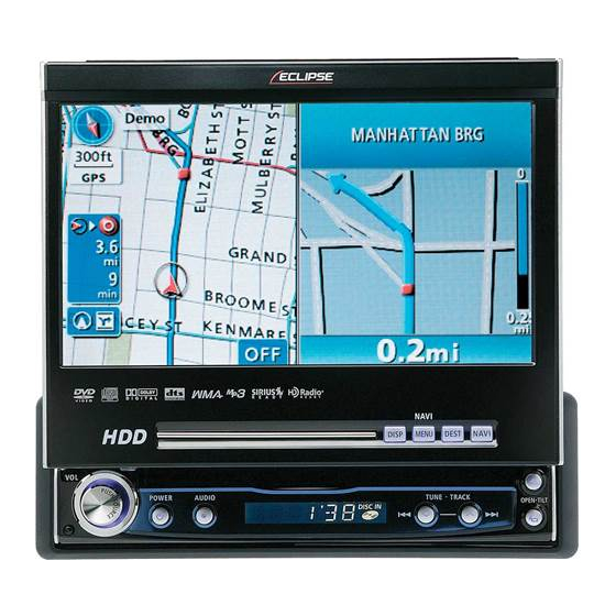
Hdd navigation system with 7" wide tft display and dvd/ms multi-source receiver
Hide thumbs
Also See for AVN7000:
- User manual (184 pages) ,
- Brochure (36 pages) ,
- User manual (15 pages)
Table of Contents
Advertisement
Quick Links
HDD Navigation System with 7" Wide TFT Display and DVD/MS Multi-Source Receiver
INSTALLATION MANUAL
Be sure to read this installation manual thoroughly prior to installation and making connections. If
installation methods or non-standard parts not specified in this installation manual are used, accidents
or injury may result.
Professional installation is recommended, contact the place of purchase to schedule an appointment.
After reading the owner's manual and the installation manual thoroughly, keep them in a safe place for
later reference.
To dealers:
Give this installation manual to the customer after installation and all connections have been
completed.
Contents
Contents
Before
installation
Connections
Installation
MODEL
Components
For your safety in using the AVN7000
Installation Diagram
Names and functions of terminals
Connecting the vehicle speed pulse, parking brake, and reverse cables (wires)
System connection example
Installing the GPS antenna
Installing the main unit
2
3
5
6
10
12
16
19
Advertisement
Table of Contents

Related Manuals for Eclipse AVN7000


Summary of Contents for Eclipse AVN7000
-
Page 1: Installation Manual
Give this installation manual to the customer after installation and all connections have been completed. Contents Contents Components Before For your safety in using the AVN7000 installation Installation Diagram Names and functions of terminals Connections Connecting the vehicle speed pulse, parking brake, and reverse cables (wires) - Page 2 Waterproof cushion Wiring components Clamp (for GPS antenna) When installing the main unit, some vehicle models may require the use of items that need to be obtained separately such as a power supply adaptor cable, radio antenna adaptor cable or mounting bracket.
- Page 3 Warnings and caution signs, illustrated bellow, are posted throughout this manual as well as on the AVN7000. They show safe and correct ways to handle the product to prevent personal injury to you and others and avoid damage to property.
- Page 4 • • Do not place the vinyl storage bag over a person's head. It may cause a serious accident or death by suffocation. • • Do not disassemble or rebuild this product. Doing so may cause an accident, fire, or electrical shock. •...
- Page 5 (When installing outside the vehicle) • • If installing the GPS antenna inside the vehicle, the location and the slope of the vehicle's windshield will determine the accuracy of the GPS antenna to receive the GPS signal. If the GPS antenna location inside the vehicle is hindering the accuracy of the GPS antenna, then you may want to install the antenna outside of the vehicle.
- Page 6 INTERCONNECTING CABLE (E-lan etc) MAIN UNIT GPS ANTENNA • • Refer to page 7 for details on the wire colors and connection points for interconnecting cables • • Refer to page 8 for details on connection points terminals.
-
Page 7: Wire Colors, Connection Points For Cables
Wire colors and connection points for connection cables Never connect the power supply to the speaker leads (No.6 and No.7), otherwise it will cause damage to the main unit. Caution B+ (Yellow) Connect where power is constantly available, regardless of the ignition key's position. ACC (Red) Connect where the power comes on when the ignition is in the ACC position. - Page 8 Connect to the monitor with video input. Yellow : Video signal Back-eye camera external input terminal (4P) Used with the Eclipse back-eye camera (sold separately). E-LAN terminal (13P) Connect to the E-LAN terminal of the CD changer, etc. Main unit connections Front line-out terminal Connect to the RCA connector of an external amplifier.
- Page 9 - Vehicle connections - • • You will need to purchase the necessary component adapter cable for the vehicle so that the power supplies can be utilized. (Contact the dealer for further details.) • • Be sure to wrap the connection cables with plastic tape to insulate them. - Example of using vehicle adapter cables - Power supplies for combined...
- Page 10 The locations where the vehicle speed pulse signal cable, parking brake signal cable, and reverse cable may vary depending on the vehicle model and grade. Ask the car dealer or your nearest Eclipse dealer for details. - A connecting point for the vehicle speed pulse signal (example) -...
- Page 11 - A connecting the point for parking brake (example) - Use a splicing connector to connect the parking brake signal cable (red/white) coming from the main unit to the parking brake signal cable of the vehicle. Route the parking brake signal cable to the main unit.
- Page 12 • • If removing the end of the cord to connect to another cord, be sure to wrap PVC tape or a similar wire insulating method around the connection to insulate it. If the connection is not insulated, fire or accidents may result. ■ AVN7000 + HDR105 + TVR105 + CH3083 MAIN UNIT If not connecting a device such as a DCU105 (sold...
- Page 13 • • Install and connect all of the peripheral units before connecting them to the main unit. • • Do not remove any of the protective caps (RCA, etc.) unless in use. • • Be sure to wrap the connection cables with tape (PVC tape) to insulate them. ANTENNA EXTENSION CABLE INTERCONNECTING CABLE (supplied with HDR105)
-
Page 14: System Connection Example
System connection e System connection e ■ AVN7000 + DCU105 + HDR105 + TVR105 + CH3083 These speaker cables are not used when connecting an external amplifier. If not using an external amplifier, connect the front and rear speakers using these speaker cables. - Page 15 Tip*1 - Speaker connection examples - For a front 3-way speaker system To center speaker (with amplifier) or To external amplifier external amplifier To external amplifier CENTER REAR To external anplifier To external amplifier To sub woofer (with amplifier) or external amplifier •...
- Page 16 If it becomes wound or entangled around parts such as the steering wheel, shifting lever, or brake pedal, accidents may result. • • Do not install the GPS antenna where it will obstruct the driver's vision or where it will be an obstacle while driving, otherwise traffic accidents may result.
- Page 17 Install the GPS antenna to the ground plate. If installing the GPS antenna inside the vehicle, the installation location and the shape of the vehicle's body will determine GPS accuracy. Accuracy is usually lower when the GPS antenna is installed inside the vehicle.
- Page 18 Remove the backing paper from the body protective sheet and attach the sheet to the vehicle. Install the GPS antenna on top of the body protective sheet. Route the GPS antenna cable inside the vehicle's trunk and secure it with clamps.
-
Page 19: Installing The Main Unit
Installing the main unit Installing the main unit - Installation angle - To maintain proper function, the unit must be mounted less than 30 degrees. If the angle is in excess of 30 degrees, DVD/CD skipping and improper DVD/CD and Memory Stick ejection may occur. - Page 20 Front of vehicle Screw position By adjusting the positions of the brackets, the main unit's installed depth can be adjusted. “ECLIPSE” is a registered trademark of FUJITSU TEN LIMITED in 48 countries including the U.S. and Japan. - 20 -...
Need help?
Do you have a question about the AVN7000 and is the answer not in the manual?
Questions and answers