Table of Contents
Advertisement
Quick Links
Quick Start
Overview
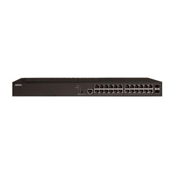
This quick start describes how to install, configure, and troubleshoot the SDX 8110-24-740W, 24-port Managed GbE 740W PoE+ Switch.
Figures 1 and 2 show the Front and Rear Panel layouts of the switch.
■
"Installing the Switch"
on page 1
■
■
■
■
■
SDX 8110-24-740W
Installing the Switch
Package Contents
■
SDX 8110-24-740W switch
■
AC power cord
■
DB-9 to RJ-45 cable
■
Micro-USB to USB cable
■
Four adhesive rubber feet
■
Mounting kit for rack mount (two brackets and eight screws)
■
Quick Start
f
WARNING!
The SDX 8110-24-740W is intended for indoor use only. Ethernet, PoE cables and attached equipment are intended for use within the
same building with equa-potential bonding, and not intended to be placed in separate buildings or structures. Failure to deploy as
described could result in permanent damage from lightning or other electrical events and voids the warranty.
SDX 8110-24-740W
24-port Managed GbE 740W PoE+ Switch
on page 4
on page 6
on page 6
on page 7
on page 8
Figure 1. Front Panel Layout
LINK/ACT/SPD
SYS
Mode LED
LED
SYSTEM
LNK/ACT/SPD
PoE
Mode LED
Figure 2. Rear Panel Layout
CONSOLE
Port
PoE
USB
MODE/RESET
CONSOLE
1
2
3
4
5
6
MODE
Button
617108124PF2-13C
10/100/1000
RJ-45 with PoE+
7
8
9
10
11
12
13
14
15
16
17
18
19
Port Status
LEDs
AC Line: 100-240V 50-60Hz
Power Connection
AC Line: 100-240V 50-60Hz
July 2019
P/N: 17108124PF2
1G/10G
SFP+ Ports
20
21
22
23
24
25
26
Advertisement
Table of Contents

Related Manuals for ADTRAN SDX 8110-24-740W


Summary of Contents for ADTRAN SDX 8110-24-740W
-
Page 1: Quick Start
WARNING! The SDX 8110-24-740W is intended for indoor use only. Ethernet, PoE cables and attached equipment are intended for use within the same building with equa-potential bonding, and not intended to be placed in separate buildings or structures. Failure to deploy as... -
Page 2: Installation Overview
3. Secure the brackets to the posts by inserting rack screws and tightening them with an appropriate screwdriver. NOTE Rack mount brackets are a default accessory with the unit; spare brackets can be ordered through ADTRAN, part number: 1700519F1. Figure 4. Attaching Brackets to the Rack Post... - Page 3 The SDX 8110-24-740W must be mounted in the face down orientation when wall mounted. Figure 6. Install Screws in the Wall and Hang the Switch on the Screws NOTE The wall mount brackets are not supplied with the unit and must be purchased separately from ADTRAN, part number 1700520F1. 617108124PF2-13C...
-
Page 4: Initially Configuring The Switch
Connect AC Power To connect the AC power cord to the switch, complete the following steps. 1. Connect the AC power cord to the AC power receptacle on the rear panel of the switch. 2. Connect the other end of the AC power cord to a properly grounded AC power outlet. 3. - Page 5 Initial Switch Configuration Using a Web Browser After powering up the switch for the first time, you can perform the initial switch configuration using a web browser. To begin with the initial configuration stage, you need to reconfigure your PC’s IP address and subnet mask to make sure the PC can communicate with the switch.
- Page 6 Initial Switch Configuration Using CLI The CLI can be accessed using any one of the two console ports (USB & RJ45) available in the switch. To establish the connection to the console port, the following are needed: ■ PC with VT100 terminal emulation software ■...
-
Page 7: Port Status Leds
Port Status LEDs The Port Status LEDs indicate the current status of each port in either Link/Act/Speed mode or PoE mode. By pressing the MODE button for less than two seconds, you can change LED modes from LINK/ACT/SPD mode to PoE mode, to check the port status in each mode. When LINK/ACT/SPD Mode LED Is Lit When the LINK/ACT/SPD Mode LED is lit, the link/act/spd status is indicated by the LED behavior. -
Page 8: Troubleshooting The Switch
SDX SMB Switches Command Reference Guide For inquiries, go to: http://adtran.com/training Warranty: ADTRAN will replace or repair this product within the warranty period if it does not ADTRAN CUSTOMER CARE: meet its published specifications or fails while in service. Warranty information can be From within the U.S.
Need help?
Do you have a question about the SDX 8110-24-740W and is the answer not in the manual?
Questions and answers