Plus Copyboard N-31W User Manual
Network board
Hide thumbs
Also See for Copyboard N-31W:
- Service manual (38 pages) ,
- User manual (36 pages) ,
- Manual (32 pages)
Table of Contents
Advertisement
Quick Links
Copyboard
(Network board)
N - 31S/N - 31W/N - 314
User's Manual
Thank you for your purchase of the PLUS Copyboard.
Please read this User's Manual carefully before use to take full advan-
tage of the functions of this product. After you have finished reading
the manual, please keep it for future reference.
Advertisement
Table of Contents

Related Manuals for Plus Copyboard N-31W


Summary of Contents for Plus Copyboard N-31W
- Page 1 N - 31S/N - 31W/N - 314 User’s Manual Thank you for your purchase of the PLUS Copyboard. Please read this User’s Manual carefully before use to take full advan- tage of the functions of this product. After you have finished reading...
-
Page 2: Introduction
• Use only the power cord and AC power adapter supplied with the network board. The supplied power cord and AC power adapter cannot be used with other products. • You will be punished for merely owning illegal copies. • Do not use ruled type tapes. Do not move the sheet with tape, etc., attached to it. Doing so could result in malfunction. • Do not attach any paper on the sheet. Do not copy while film-type objects or papers are attach to the sheet. Doing so could result in malfunction. Trademarks and copyrights • Microsoft and Windows are registered trademarks or trademarks in the United States and other countries of the Microsoft Cor- poration. • Adobe and Adobe Acrobat Reader are trademarks of Adobe Systems Incorporated. • Safari, Apple, Mac OS and Macintosh are trademarks or registered trademark of Apple Computer, Inc., of the United States. • Mifare is a registered trademark of NXP Semiconductors. • The copyright of CyaSSL belongs to wolfSSL Inc. The trademarks of the various companies and the product trademarks, even when not written down, will be given due respect. Product names and company names appearing in this manual are registered trademarks or trademarks of the respective compa- nies. (1) The contents of this manual may not be reprinted in part or whole without permission. (2) The contents of this manual are subject to change without notice. (3) Great care has been taken in the creation of this manual; however, should any questionable points, errors, or omissions be apparent, please contact us. (4) Notwithstanding Section (3), this company will not be responsible for any claims of loss or profit or other matters deemed to be the result of using this unit. (5) Since printer connected with the network board is based on the use as a peripheral device for the PLUS network board, we do not warrant direct connection with a computer. (6) Manuals with incorrect collating or missing pages will be replaced. -
Page 3: Table Of Contents
Table of Contents Introduction ...............E-2 Using USB Memory ..........E-20 Package Contents ............E-4 USB Memory Storage Procedure ......E-20 Names of the Parts ............E-5 Saving Image Files on a Computer/Deleting Image Files ..............E-22 Front ..............E-5 Using the network board connected to a Input/output terminals .......... -
Page 4: Package Contents
These are brackets for mounting the main unit on a wall. (See the Assembly and Setup Manual.) Upper wall brackets: 2 Lower wall brackets: 2 Main unit fixing screws (M4 × 12: 2) * Sold separately for some products. Network board Accessories USB cable (type B ↔ type A) [1] [PLUS code 715258900] Dedicated markers Cable for connecting the main unit to (One each of black, red, blue, and a computer. green) Used for making the device settings. Use these markers to draw on the sheet surface. -
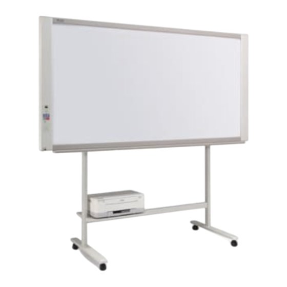
Page 5: Names Of The Parts
Names of the Parts Front Main unit Frame cover Sheet Dedicated markers are used on the sheet to draw diagrams and to write. Keypad panel (See Page E-9) Control panel (See Page E-8) Pen tray Input/output terminals (see next page) * Located on the bottom surface. Printer table The printer* is placed here. (See the N-31 Series Assembly and Setup Manual.) * The printer is sold separately. AC adapter box Store the AC power adapters of the network * This illustration does not show the connection cords. board and printer here. (See the N-31 Series Assembly and Setup Manual.) Stand This stand supports the network board. (See the * Depending on the product you have purchased, the printer may be N-31 Series Assembly and Setup Manual.) sold separately. -
Page 6: Input/Output Terminals
Names of the Parts Input/output terminals USB memory port (type A) Connect a commercially available USB memory device. Scanned images can be saved. (See page E-20) The connector is located on the bottom sur- face of the main unit. The diagram view is seen from the bottom. * This illustration does not show the printer or connection cords. DC input connector Connect this with the DC plug end of the AC power Personal computer (PC) dedicated USB adapter. (See Page E-35.) (Only connect the supplied port (Type B) AC power adapter; nothing else.) Connect this with the USB port (type A) of the PC. Used to do the Simple Network Settings for this product. (Refer to the separate “N-31 Series Network LAN terminal (RJ-45) Manual”.) Can also be used to copy scanned images Connect a commercially available LAN cable. -
Page 7: Changing The Height Of The Unit
Names of the Parts Changing the Height of the Unit This is the height adjustment when setting up the network board on the optional stand. The stand height can be adjusted to 3 levels by 100 mm. CAUTION • At least two persons should hold the main unit. If not, the main unit could drop or tip, resulting in accidental injury. • Lock the stand’s casters by pressing the bottom of the caster lock button. If not, the stand could move while the main unit is being mounted or removed, resulting in accidental injury. • After unplugging the power cord from the wall power outlet, disconnect all the connection cords from the set’s input/ output terminals. If the set is removed without disconnecting the cords, it could tip, resulting in accidental injury. • If a printer is mounted on the set, remove the printer before starting. If not, the stand could tip while the main unit is being mounted or removed, resulting in accidental injury due to the printer dropping or tipping over. -
Page 8: Control Panel
Names of the Parts 4 Consecutive printing number indicators Control Panel These light yellow to indicate the number of screens selected with the consecutive button. The control panel of the drawing refers to Model 5 Thumbnail ( ) ( on N-314) button N-31S/N-31W. Used to select the layout for printing thumbnails of mul- When pressing a button, please press the center area tiple screens on a single page. -
Page 9: Keypad Panel
Names of the Parts IC Card indicator Status of IC card Keypad panel Lit red IC card error in read/write (3 sec- onds) When pressing the button, press the center area (the square Not accept IC card bulge). The button may not work if it is pressed on a corner. The indicator lights off in the follow- ing condition: • “Network Setting” is not done. • “Network Storage” in “Security Setting” is set to “Invalid”. • In operation 1 IC card read/write part Touch the supplied IC card here. Reads or writes data to the IC card. -
Page 10: Functions Of The Network Board
Functions of the Network board Printing Functions ① ② Printing Printing thumbnails of multiple screens on a single page Printing of thumbnails on single page Output to paper ③ ④ Printing or storing multiple screens con- Print to the network printer. secutively Consecutive printing or storing, one screen at a time FTP supported printer * Printing of thumbnails of 2 screens and consecutive on Model N-31S/N-31W. E-10... -
Page 11: Saving Functions
Functions of the Network board Saving Functions ⑤ ⑥ Storing on USB memory devices Capturing images on a computer Storing on USB memory device Storing of image on computer ⑦ ⑧ Viewing images stored on the network Storing images on an FTP server via a net- board via a network work Network board’s memory Viewing of Viewing of images stored images stored on the network on FTP server board ⑨ ⑩ Using the IC card to store images on a spe- Using an ID number to store images on an cific folder on an FTP server. FTP server or on a specific folder in the network board. Entering ID number Blip! Network board’s memory FTP server FTP server Viewing Viewing Save location Save location... -
Page 12: Operation Steps
Operation Steps The network board uses an image scanner to scan characters or diagrams drawn using special markers (four colors). The image can be printed out to the printer and be stored on a USB memory device or a computer. When network settings are made with a network connected to the network board, the image can be saved on the network board or a FTP server, or can be printed out to the network printer on the network. -
Page 13: Setting The Time
Setting the Time The date and time are stamped on the printing paper and recorded in the file information when files are stored on the network board and FTP server, so set the network board’s time correctly. The time can also be set from a computer via a network (when connected to a LAN). - Page 14 Setting the Time While “F1” is displayed, press the Save button to enter. The display switches to “c1” (first 2 digits of year). If no buttons are operated for 10 seconds while in the time setting mode, the mode returns to the “CB Setup” mode. Press the Save button to move to the last dig- its of the year The display switches to “c2” (last 2 digits of year). Notice: The first two digits of the year (“20”) are fixed. Simply press the Save button to switch to the last 2 digits of the year setting position. Use the Network Print (Increase) and On Board Print (Decrease) buttons to select “13” (the last...
-
Page 15: Printing (Printer Sold Separately
Printing (printer sold separately) Use a printer to print out the image that has been drawn on the sheet surface. Use a PLUS-designated printer. Operations and names of parts differ from printer to printer. For details of operations, see your printer’s operat- ing instructions. The network board can print out to the printer connected to the network board or a network. -
Page 16: Basic Printing Operation
Printing Basic Printing Operation Preparation: Preparation: Check that the AC power plugs of the network board and printer are con- nected to wall power outlets. Press the ON/Standby button and switch on the power. Prepare the printer. (See the previous page.) Note • When turning on the power, wait about 5 seconds or more after the power plug has been connected before pressing the ON/Standby button. • Press the ON/Standby button to switch on the power. The LED of the display window will light. • Turn on the network board’s power before turning on the printer’s power. Press the Scroll/Stop or button and display the sheet surface you want to print. - Page 17 Printing Note • “01” is selected when the power is turned on. • Up to 10 copies can be specified and displayed on the display window. • The number of copies increases by 1 each time the Number of Copies button is pressed, and “ ” is displayed after “10” (this is used for test printing: see page E-32). When the button is pressed again, the display switches to “01”. The number switches continuously if the button is held in. • After setting the number of copies, proceed to step 4 within 1 minute. The number of copies is reset to “01” if no operation is performed within 1 minute. Press the Network Print or the On Board Print button to print. The reading operation is performed for a one-sheet portion (while the sheet is scrolled) and the printing operation is per- formed. To change printing color (Color or B/W), perform thumbnail printing or continuous printing, make each setting (see next page) and press the appropriate Print button. Notice • To use the network printing function, connect the FTP supported printer to the same network where the network board is located, and make the printer settings on the network board. Cancellation of the print operation in progress When the ON/Standby button is pressed, the reading of the sheet stops, and the partially read image data is printed. Wait until the sheet is expelled from the printer. Note • If the ON/Standby button is pressed while the sheet surface is being read, printing is interrupted and only part of the image will be printed. • The one-screen portion is reduced to A4 paper size and printed. For wide type network boards (model N-31W), the image is compressed about 75% in the horizontal direction. To print with the same proportions as the image on the sheet surface, see “CB Setup (Operating the Network Board’s Buttons)” (page E-26).
-
Page 18: Moving The Sheet Surface Manually
Printing Moving the sheet surface manually The sheet can be moved even when the power of the network board is switched off. The sheet can be moved with your hand either in left or right. Please place your hand at the vertical center and move the sheet slowly. Notice • Quick movement can cause damage to the drive mechanism of the network board. Note • When the Erase Reminder function is set to “Enable”, the Erase Reminder function may not operate properly if the sheet surface is moved by hand. Printing Thumbnails Multiple screens from the screen at the current position can be printed on a single page. • The thumbnail printing function is for printing only. Storing with the Save or Network button is not possible. Press the Thumbnail button and select the page layout. Display window status and page layout Thumbnail Movement of display win- Page layout (Button on model N-314) selection dow LEDs The mode switches in the following order each time the Thumbnails of 2 button is pressed. -
Page 19: Consecutive Printing
Printing Consecutive Printing Multiple screens from the screen at the current position can be printed (or stored). Press the Continue button and select the number of screens. Consecutive printing Consecutive printing number number indicators indicators One lit: Cancel (single- One lit: Cancel (single-screen printing/storing) screen printing/storing) Two lit: Screens 1 and 2 printed/stored consecutively Two lit: Screens 1 and 2 Three lit: Screens 1 to 3 printed/stored consecutively printed/stored consecu- Four lit: Screens 1 to 4 printed/stored consecutively (Button on model tively N-314) The mode switches in the following order each time the button is pressed. Screens 1 and 2 → Cancel ... (Screens 1 and 2 → Screens 1 to 3 → Screens 1 to 4 → Cancel ... on model N-314) The number of consecutive screens is indicated by the number of consecutive printing number indicators that are lit yellow. -
Page 20: Using Usb Memory
Using USB Memory The content of what has been drawn on the sheet surface of the network board can be saved in USB memory. Later, the saved image can be read into a personal computer and made into a document of the proceedings of the meeting, or affixed to a document. - Page 21 Using USB Memory Press the Save button to store. Flashing indicator “rotates” sequentially during USB memory storage operation. Display window • The reading operation is performed for a one-sheet portion (while the sheet is scrolled) and USB memory storage starts after the scrolling completes. • Multiple screens can be stored consecutively. (See Page E-19, “Consecutive Printing”.) The (5 second) flashing “US” display indicates that the USB memory has not been inserted. Please insert the USB memory and then press the Save button. A (5 second) flashing “FL” display indicates that there is insufficient free capacity to permit storage in USB memory. Replace with a USB memory device having sufficient capacity. See “Meaning of Error Messages” on Page E-29 for other error displays. Note • Depending on the USB memory, it may take time for recognition or it may take time for saving. • When the ON/Standby button is pressed during the reading operation, the reading operation will be discontin- ued and the partially read image data will be stored in the USB memory.
-
Page 22: Saving Image Files On A Computer/Deleting Image Files
Using USB Memory Saving Image Files on a Computer/Deleting Image Files Examples of operations follow for saving the image files in the USB memory device to the hard disk of the per- sonal computer, and for deleting the folder when the USB memory capacity is full. (There are various methods that can be used for saving and deleting including the use of Explorer.) See the instruction manual of your per- sonal computer or the software that you are using for information about using a personal computer. - Page 23 Using USB Memory Deleting USB memory image files with the com- puter Before deleting important image files, be sure to save them on the computer (as a data backup). Open “My Computer (or “Computer”)” and then open the drive icon which shows USB memory. The folder named “CB_Image” contains the memory stor- age data of the network board. Place the “CB_Image” folder in the “Recy- cle Bin”, right click on the icon and select “Empty Recycle Bin” from the pull-down menu. All of the data contained in “CB_Image” will be deleted. Even when the entire folder is deleted, a new CB_Image folder will be created automatically when USB memory is Drag to the Recycle Bin used again with the network board.
-
Page 24: Using The Network Board Connected To A Computer
Using the network board connected to a computer When the network board and a computer are connected by USB cable, the network board is recognized as an external memory device (removable device). Below is the procedure for copying the “CBImage” file from this device onto the computer. Images can be stored in JPEG (.jpg), PNG (.png) or PDF (.pdf) format, selectable in the network board settings (“CB Setup”). - Page 25 Using the network board connected to a computer On the computer, open “My Computer”, and from there open the network board identified as a removable device. (1) Double-click the “My Computer” (or “Computer”) icon to open (2) When the device icon for the network board (displayed as a removable disk) is double-clicked, the network board’s inter- nal memory opens. The “CBImage” file is the scanned image file (“.jpg”, “.png” or “.pdf”, according to setting). • The “setup” folder contains the simple network settings file. (3) Copy the “CBImage” file to [My Documents], etc., on the computer (“.jpg”, “.png” or “.pdf”, according to setting).
-
Page 26: Cb Setup (Operating The Network Board's Buttons
CB Setup (Operating the Network Board’s Buttons) There are two ways to make the device settings: using the network board’s operation buttons to make the set- tings (“CB Setup”) and making the settings via the web on the computer connected to a network. The description here provides operation using the network board’s buttons. For using the network board connected to a network, refer to the separate “N-31 Series Network Manual”. -
Page 27: Table Of Function Numbers And Settings
CB Setup (Operating the Network Board’s Buttons) Table of Function Numbers and Settings Function Setting Item Description Setting Status Indicators Number The date and time are stamped on the printing paper Year, month, Not lit Time Setting and recorded in the file information when files are day, hours, stored. minutes Selection of whether to print in A4 paper size or letter Color Print size. (Lit) (Off) Paper Size • This operates when the network board is con- Letter Color Print nected to a printer. - Page 28 CB Setup (Operating the Network Board’s Buttons) Function Setting Item Description Setting Status Indicators Number Setting of whether or not to notify the user that char- Disable* Color Print acters or diagrams drawn on the back side of the (Lit) (Off) network board’s sheet surface have not been erased. Enable Color Print This is effective for confidential meetings, etc. (Off) (Lit) Disable: T he Erase Reminder function does not work. (Setting upon factory shipment) Enable: W hen the ON/Standby button is pressed to Erase Reminder turn the power off, the display window on the network board’s operation panel flashes...
-
Page 29: Meaning Of Error Messages
When the “USb” letter display is • Did you press the ON/Standby button • A USB memory device is plugged into flowing...Warning that disconnec- while the USB memory device was plugged the main unit. When the USB memory tion of USB memory has been for- into the main unit? device is disconnected, the power will gotten be switched off and the unit will enter the standby mode. If the problem persists, please contact your nearby PLUS Corporation sales office, dealer, or store. E-29... - Page 30 Meaning of Error Messages Network (main unit) related errors Error Display Number Problem and Solution LAN cable dis- • No cable is connected to the LAN terminal. • Connect the LAN cable properly. connected FTP server rec- • The user name or password is wrong. • Input the correct user name and pass- ognition error word. (Refer to the separate “N-31 Series Network Manual”.) FTP server con- • The FTP server’s IP address is wrong. • Consult the network administrator then nection failure set the FTP server’s IP address. (Refer to the separate “N-31 Series Network Manual”.) FTP server writ-...
-
Page 31: Troubleshooting
PC does not recognize the the USB cable is connected properly. network board • Is the network board connected to the PC via a USB hub? (Connect the network board directly to the USB port of the PC.) The date is not updated. • The network board’s battery is dead. Contact your store of purchase. * If the problem persists, please contact your nearby PLUS Corporation sales office, dealer, or store. Condition Please Check The network board’s power turns on, but • Check whether the printer’s power plug (DC plug) is securely inserted. the printer’s power does not. If the power still does not turn on, check whether the printer’s AC power adapter side plug is unplugged from the AC power adapter. (For some print-... - Page 32 • Is “Caps Lock” set on the computer’s keyboard while inputting the user name and password? Printing is not possible when Network Print • Set the Printer Setting in the “Network Setting”*. button is pressed. * For setting or checking for network, refer to the separate “N-31 Series Network Manual”. Test Printing 1) With the network board’s power on (with the display window lit), press the Number of Copies button repeatedly to display “ ” on the display window. 2) Press the Color / B/W button to select a printing color mode and press the On Board Print button. * Test printing starts. Check the print • Is the each color line printed uniformly? • Are there missing dots, pale lines, lines with thinner ink than others, etc.? Remedy • If the nozzle is partially choked, clean it. • If the quality of the print does not improve even though the nozzle has been cleaned, wipe off the ink on the surface of the nozzle. For details, see the “User’s Guide” included with the printer. * Please see your printer manual for information about printing problems, printer maintenance, and details related to printing. Updating the network board’s internal program See the PLUS website for instructions on updating the program and to download the latest program. E-32...
-
Page 33: Scanning Adjustment (White Calibration
Scanning Adjustment (White Calibration) If dark lines (horizontal black lines) on a printed out hard copy or image on the screen are generated, you need to optimally adjust the sensitivity of reading the sheet surface. If the scanning image does not work due to generation of dark lines, update the program and perform the white calibration in the following steps. -
Page 34: Specifications
Specifications BOARD TYPE (Model name) Standard (N-31S) Wide (N-31W) 4-screen (N-314) Installation method Self-standing (T-shaped legs), or wall mounting External dimensions (T-shaped W1480 × D675 × H1947*² W1980 × D675 × H1947*² W1480 × D675 × H1947*² legs*¹) Form Main unit weight 20 kg*³... -
Page 35: Appendix
Appendix Connections and Wiring Diagram • The connections and wiring diagram below is included here for checking the connections. [Network board and Printer Connections Diagram] Network board front panel To Printer connector To DC INPUT connector USB cable (supplied with the printer) To USB connector Printer To DC connector Printer AC power adapter AC power adapter (supplied) (supplied with the printer) To wall power outlet * Appearance of printer is for illustration purposes. Note • The AC power adapters of accessories and printers that have been verified to be operation many differ from the ones shown on the connections diagram (they may be of the built-in or mounted-on type). - Page 36 ISO 14001 cer tification. © 2011 PLUS Corporation 26-4695-14C...
Need help?
Do you have a question about the Copyboard N-31W and is the answer not in the manual?
Questions and answers