Table of Contents
Advertisement
Quick Links
Advertisement
Table of Contents

Related Manuals for Plus Copyboard N-324


Summary of Contents for Plus Copyboard N-324
- Page 1 Copyboard N-324 SERVICE MANUAL 7/20.2018. Ver.1.0...
-
Page 2: Table Of Contents
CONTENTS 5. ADJUSTMENT............18 1. COMPLIANCE OF SAFE REPAIR ......3 5-1. Calibration............18 1-1. Cautions during Product Movement ....3 5-2. Changing the Internal Program of N-324 Main Set..19 1-2. Cautions during disassemblying and assembling ...3 5-3. Test mode............20 2. SPECIFICATIONS .............4 6. -
Page 3: Compliance Of Safe Repair
1. COMPLIANCE OF SAFE REPAIR Be sure to read this Service Manual before providing services. In the PLUS Copyboard, full consideration is taken to ensure the safety for a fire, electric shock, injury, harmful radiation, and substance. Therefore, observe the notice described in this Service Manual so that the safety is kept when providing services. -
Page 4: Specifications
2.SPECIFICATIONS 2-1. Product Specifications BOARD TYPE (Model name) 4-Screen (N-324) Installation method Self-standing (T-shaped legs), or wall mounting E x t e r n a l d i m e n s i o n s W1480 × D675 × H1947*² mm Form (T-shaped legs*¹) Main unit weight... -
Page 5: Names Of The Parts
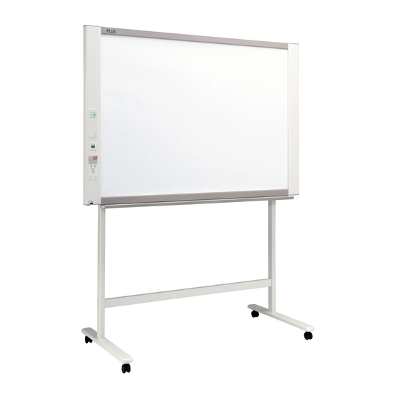
SPECIFICATION 2-2. Names of the Parts Front Main Unit Frame Cover Sheet Dedicated markers are used on the Sheet to draw diagrams and to write. NFC Panel (Numeric panel) Control Panel Input/output terminals Pen Tray (see next page) * Located on the bottom surface. Printer Table The printer* is placed here. - Page 6 SPECIFICATION Input/output terminals The figure is viewed from the back. Rating label (Serial number) USB memory port (type A) Connect a commercially available USB memory device here. Scanned images can be saved. USB B USB A MEMORY The connector is located on the bottom surface of the Main Unit.
-
Page 7: Control Panel
SPECIFICATION 2-3. Control Panel When pressing a button, please press the center area (the square bulge). The button may not work if it is pressed on a corner. 7 Save ( ) button (USB memory storage) The sheet is moved by 1 screen and read, and the image is stored N-324 on the USB memory device. -
Page 8: Numeric Panel
SPECIFICATION 2-4. NFC panel (Numeric panel) When pressing the button, press the center area (the square bulge). The button may not work if it is pressed on a corner. 1 IC card read/write part Touch the IC card here. Performs reading of IC cards or writing onto dedicated IC card. -
Page 9: Meaning Of Error Messages
SPECIFICATION 2-5. Meaninig of Error Messages N-324 If any of the following flashing indications appear in the display window of the control panel, please check the matters described below. Error messages flash for 5 seconds, then stop flashing, remaining lit. Error Display Number Problem and Solution •... -
Page 10: Trouble Shooting
3.TROUBLE SHOOTING By checking operations, it is possible to carry out judgments on malfunction to a certain extent. Carry out the following checks before disassembling the equipment. 1. Press the Standby (On) button and turn on the power. Is the power turned on? No →... - Page 11 TROUBLE SHOOTING 6. Confirm the LED display on the NFC panel (Numeric panel) (during network connection). * Confirm that a network has been set so that an IC card can be used. Bring an operation confirmation IC card (not including any data) in touch with an IC card reader/writer. •...
-
Page 12: Disassembly And Assembly
4.DISASSEMBLY AND ASSEMBLY 4-1. Tools Required • Phillips screwdriver (+) No. 2 • Phillips screwdriver (–) 4-2. Caution • See “1. Compliance of Safety Repair and Safety Inspection” before disassembling and assembling. • Put on gloves so that you do not cut your hand at the sharp edge of a frame during disassembly and assembly. •... -
Page 13: Disassembly And Assembly
DISASSEMBLY AND ASSEMBLY 4.4. Disassembly and Assembly This section describes one example of disassembly and assembly procedures. For the actual operation, disassemble and assemble the required parts with reference to “4-3. Disassembly and Assembly Procedures”. * Remove the main set from the stand and proceed with the Endless Sheet. (Perform the operation on a mat.) * Remove the Pen Tray before performing the procedure below. - Page 14 DISASSEMBLY AND ASSEMBLY 2) Remove the Frame Cap PC. (See Fig. 6.) 1.Remove the “S-2” screws shown in the figure 6 and then remove the Frame Cap PC. 2.Disconnect the connector connected to the USB Board shown in the figure 7. 3.Remove the “S-3”...
- Page 15 DISASSEMBLY AND ASSEMBLY 5) Remove the Panel Side R. (See Fig. 11) 1. Remove the “S-4” screws shown in the figure 11 and then remove the Panel Side R. Panel Side R Fig.11 7) Remove the Back Panel Unit. (See Fig. 14) 1.Remove the “S-5”...
- Page 16 DISASSEMBLY AND ASSEMBLY 3.Remove the “S-3” screws shown in the figure 1.Put the protrusion from the bottom of the SW Panel when 17 and then remove the SW Board. returning the SW Panel to the former position. Note: 2.Slide the protrusion in the direction indicated by the arrow. Pay attention to the wire drawing of the SW Cable 3.Confirm that the hook of the SW Panel is completely put in during assembling.
- Page 17 DISASSEMBLY AND ASSEMBLY 10) Remove the Rear Frame. (See Fig. 23) 1.Remove the “S-6” screws shown in the figure 23 and then remove the Rear Frame (two). Rear Frame This side is located upwards. Fig.23 11) Remove the Panel Upper. (See Fig. 24) 1.Remove the “S-4”...
-
Page 18: Adjustment
5. ADJUSTMENT 5-1. Calibration Calibration is required in the following cases. • When a Main Board Assy is replaced • When a Sheet Frame Unit is replaced For the replacement of a CIS Unit in the market, usually, use a unit that has been adjusted at a factory. * Be sure to replacing the CIS Unit when any failure occurs in an image. -
Page 19: Changing The Internal Program Of N-324 Main Set
ADJUSTMENT 5-2. Changing the Internal Program of N-324 Main Set [How to rewrite program using PC] Equipment used 1) Firmware data for N-324(PX37H_N324_**_**.brn) 2) PC main set (OS: Windows 7/8/8.1/10) 3) USB Cable Preparation Save the extracted N-324 program holder on the desktop screen of PC used. 1. -
Page 20: Test Mode
ADJUSTMENT 5-3. Test mode 1. Program version display • Insert the plug of an AC Adaptor into the main set to apply the electric current (in the Standby state). • Press the Save button three times while pressing and holding the Power (ON / Standby) button. Test / adjustment mode segment display: <A.P>... -
Page 21: Device Setting
6.DEVICE SETTINGS There are two ways to make the device settings: using the network board’s operation buttons to make the settings (“CB Setup”) and making the settings via the web on the computer connected to a network. The description here provides operation using the network board’s buttons. For using the network board connected to a network, refer to the separate “N-314 Series Network Manual”. -
Page 22: Table Of Function Numbers And Setting
DEVICE SETTINGS 6-2. Table of Function Numbers and Settings Function Setting Setting Status Indicators Description Number Item The date and time are stamped on the printing paper and Not lit Year, month, day, Time Setting recorded in the file information when files are stored. hours, minutes Selection of whether to print in A4 paper size or letter size. - Page 23 DEVICE SETTINGS Function Setting Setting Status Indicators Description Number Item Setting of whether or not to notify the user that characters Disable Color Print or diagrams drawn on the back side of the network board’s (Off) (Lit) sheet surface have not been erased. This is effective for Color Print Enable confidential meetings, etc.
-
Page 24: Cable And Cable Connection
7. CABLE AND CABLE CONNECTION CN1 CIS cable 22Pin FFC CN3 Switch cable 7pin red cable CN2 Motor cable 4pin blue cable CN6 USB Board cable 8pin gray cable Unit Main board Assy 100-240VAC AC adapter 12V / 3A Network(LAN) USB Board Printer Motor USB Memory... -
Page 25: Parts List
8. PARTS LIST 1. PANEL SIDE... - Page 26 PARTS LIST 1. PANEL SIDE PARTS No. PARTS NAME Q' ty REMARK Panel Side L N-314 726117800 Panel Side R N-204 726114200 Frame Cap PC N-314 726129400 Frame Cap A N-314 726128900 Frame Cap B N-314 726129500 USB Board Assy 726580200 Tray Unit S N-31/N-314 302040...
-
Page 27: Main Board Cis Unit Cable
PARTS LIST 2. MAIN BOARD. CIS UNIT. CABLE... - Page 28 PARTS LIST 2. MAIN BOARD. CIS UNIT. CABLE PARTS No. PARTS NAME Q' ty REMARK CIS Unit 302008 Main Board Shield 726135500 Main Board N-324 726581135 Main Board Sheet 726951100 Cable Cover N-204 726123300 CIS Cable 726590200 Motor Cable 726590100 SW Cable 726590300 USB Cable...
-
Page 29: Sheet Frame
PARTS LIST 3. SHEET FRAME... - Page 30 PARTS LIST 3. SHEET FRAME PARTS No. PARTS NAME Q' ty REMARK Panel Plate A N-204 726134100 Panel Plate B N-204 726134200 Rear Frame 726310100 Back Panel Unit S 302001 Endless Sheet N-204 302022 N-31/N314 common Panel Front S Upper N-314 726118700 N-31/N314 common Panel Front S Lower N-314...
-
Page 31: Accessories
PARTS LIST 4. ACCESSORIES USA Only... - Page 32 PARTS LIST 4. ACCESSORIES PARTS NAME PARTS No. Q' ty REMARK Lot 100 Eraser 44369 NO Parts Supply Marker Set Lot 120 Marker Black 423283 Marker Red Lot 120 423284 Marker Blue Lot 120 423285 Marker Green Lot 120 423286 Assembly Manual N-31 726469300 Safety Guide...
-
Page 33: Carton
PARTS LIST 5. CARTON USA Only... - Page 34 PARTS LIST 5. CARTON PARTS NAME PARTS No. Q' ty REMARK Carton Unit N-204 302024 Carton S Upper N-204 Carton S Lower Packing A Packing B Accessary Box Spacer For Accessary Box Printer Table Stand Carton USA Only Parts Pad L USA Only USA Only Parts Pad R...
-
Page 35: N-18/N-20-T(Usa Only)
PARTS LIST 6. M-18/N-20-T USA Only T-11 T-15 T-15 T-13 T-15 T-14 T-12 T-16 T-10 S-14 S-15 S-10 S-11 S-13 S-12 S-11 S-12 S-13 S-11 T-19 T-20 T-21 S-12 T-18 T-22 S-11 T-17 S-12 T-24 T-23 T-25 T-17... - Page 36 PARTS LIST 6. M-18/N-20-T PARTS No. Q' ty PARTS NAME REMARK No Parts Supply T Stand (O/S) Side Bar 726332000 Printer Table (Stand Type) 726135900 Edge Holder 723191100 Adapter Holder 726136100 Stand Cap Upper 726321200 Stand Cap Lower 726321100 Front Caster 714660400 Back Caster 714660500...
-
Page 37: Screws & Washers
PARTS LIST 7. SCREWS & WASHERS PARTS NAME PARTS No. Q' ty REMARK M3-6 Cross Recessed Pan Head Double Sems 952530610 M4-8 Cross Recessed Low Head 961540810 M3-8 P-tight Cross Recessed Bind Head 963230810 M4-12 Cross Recessed Low Head 963941210 M4-40 B-tight Cross Recessed Bind Head 963444010 M4-10 Cross Recessed Pan Head Sems... - Page 38 PLUS Corporation Stationery Company...
Need help?
Do you have a question about the Copyboard N-324 and is the answer not in the manual?
Questions and answers