Table of Contents
Advertisement
Quick Links
Copyboard
(Network board)
N - 31S/N - 31W/N - 314
User's Manual
Thank you for your purchase of the PLUS Copyboard.
Please read this User's Manual carefully before use to take full advan-
tage of the functions of this product. After you have finished reading
the manual, please keep it for future reference.
Advertisement
Table of Contents

Related Manuals for Plus N-31S


Summary of Contents for Plus N-31S
- Page 1 N - 31S/N - 31W/N - 314 User’s Manual Thank you for your purchase of the PLUS Copyboard. Please read this User’s Manual carefully before use to take full advan- tage of the functions of this product. After you have finished reading...
-
Page 2: Introduction
Introduction This manual is for the network board (model name: N-31S/N-31W/N-314). • The models are categorized into different types. Model Type N-31S Standard size for two screens N-31W Wide size for two screens N-314 Standard size for four screens The descriptions and diagrams in this manual refer to the model N-31S. For using a network, refer to “N-31 Series Network Manual”. * When functions or operations are specific to a certain model of network board, the model name is speci- fied. NOTE • Use only the power cord and AC power adapter supplied with the network board. -
Page 3: Table Of Contents
Table of Contents Introduction ...............E-2 Using USB Memory ..........E-20 Package Contents ............E-4 USB Memory Storage Procedure ......E-20 Names of the Parts ............E-5 Saving Image Files on a Computer/Deleting Image Files ..............E-22 Front ..............E-5 Using the network board connected to a Input/output terminals .......... -
Page 4: Package Contents
The package contents are as described below. Please check before use. Main unit [1] Pen tray [1] Printer* [1] Pen tray fixing screws (M4 × 20) (temporarily fastened on Please see the instruction manual of the printer for informa- main unit) tion about the printer accessories. N-31S/N-314: 3 screws, N-31W: 4 screws * Depending on the type of product you have purchased, (See the N-31 Series Assembly and Setup Manual for the printer may be sold separately. assembly instructions.) Stand [1] A mobile stand (with casters) for supporting the main unit. -
Page 5: Names Of The Parts
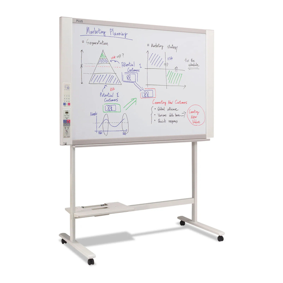
Names of the Parts Front Main unit Frame cover Sheet Dedicated markers are used on the sheet to draw diagrams and to write. Keypad panel (See Page E-9) Control panel (See Page E-8) Pen tray Input/output terminals (see next page) * Located on the bottom surface. Printer table The printer* is placed here. (See the N-31 Series Assembly and Setup Manual.) * The printer is sold separately. AC adapter box Store the AC power adapters of the network * This illustration does not show the connection cords. board and printer here. (See the N-31 Series Assembly and Setup Manual.) Stand This stand supports the network board. (See the * Depending on the product you have purchased, the printer may be N-31 Series Assembly and Setup Manual.) sold separately. -
Page 6: Input/Output Terminals
Names of the Parts Input/output terminals USB memory port (type A) Connect a commercially available USB memory device. Scanned images can be saved. (See page E-20) The connector is located on the bottom sur- face of the main unit. The diagram view is seen from the bottom. * This illustration does not show the printer or connection cords. DC input connector Connect this with the DC plug end of the AC power Personal computer (PC) dedicated USB adapter. (See Page E-35.) (Only connect the supplied port (Type B) AC power adapter; nothing else.) Connect this with the USB port (type A) of the PC. Used to do the Simple Network Settings for this product. (Refer to the separate “N-31 Series Network LAN terminal (RJ-45) Manual”.) Can also be used to copy scanned images Connect a commercially available LAN cable. -
Page 7: Changing The Height Of The Unit
Names of the Parts Changing the Height of the Unit This is the height adjustment when setting up the network board on the optional stand. The stand height can be adjusted to 3 levels by 100 mm. CAUTION • At least two persons should hold the main unit. If not, the main unit could drop or tip, resulting in accidental injury. • Lock the stand’s casters by pressing the bottom of the caster lock button. If not, the stand could move while the main unit is being mounted or removed, resulting in accidental injury. • After unplugging the power cord from the wall power outlet, disconnect all the connection cords from the set’s input/ output terminals. If the set is removed without disconnecting the cords, it could tip, resulting in accidental injury. • If a printer is mounted on the set, remove the printer before starting. If not, the stand could tip while the main unit is being mounted or removed, resulting in accidental injury due to the printer dropping or tipping over. -
Page 8: Control Panel
The control panel of the drawing refers to Model 5 Thumbnail ( on N-314) button N-31S/N-31W. Used to select the layout for printing thumbnails of mul- When pressing a button, please press the center area tiple screens on a single page. (the square bulge). The button may not work if it is The selected layout is indicated on the display window. -
Page 9: Keypad Panel
Names of the Parts Keypad panel Lit red IC card error in read/write (3 sec- onds) Not accept IC card When pressing the button, press the center area (the square The indicator lights off in the follow- bulge). The button may not work if it is pressed on a corner. ing condition: • “Network Setting” is not done. • “Network Storage” in “Security Setting” is set to “Invalid”. • In operation 1 IC card read/write part Touch the supplied IC card here. Reads or writes data to the IC card. Touch the touch mark with the IC card. Touching other places than the touch mark may cause an error. -
Page 10: Functions Of The Network Board
Functions of the Network board Printing Functions ① ② Printing Printing thumbnails of multiple screens on a single page Printing of thumbnails on single page Output to paper ③ ④ Printing or storing multiple screens con- Print to the network printer. secutively Consecutive printing or storing, one screen at a time FTP supported printer * Printing of thumbnails of 2 screens and consecutive on Model N-31S/N-31W. E-10... -
Page 11: Saving Functions
Functions of the Network board Saving Functions ⑤ ⑥ Storing on USB memory devices Capturing images on a computer Storing on USB memory device Storing of image on computer ⑦ ⑧ Viewing images stored on the network Storing images on an FTP server via a net- board via a network work Network board’s memory Viewing of Viewing of images stored images stored on the network on FTP server board ⑨ ⑩ Using the IC card to store images on a spe- Using an ID number to store images on an cific folder on an FTP server. FTP server or on a specific folder in the network board. Entering ID number Blip! Network board’s memory FTP server FTP server Viewing Viewing Save location Save location... -
Page 12: Operation Steps
Operation Steps The network board uses an image scanner to scan characters or diagrams drawn using special markers (four colors). The image can be printed out to the printer and be stored on a USB memory device or a computer. When network settings are made with a network connected to the network board, the image can be saved on the network board or a FTP server, or can be printed out to the network printer on the network. -
Page 13: Setting The Time
Setting the Time The date and time are stamped on the printing paper and recorded in the file information when files are stored on the network board and FTP server, so set the network board’s time correctly. The time can also be set from a computer via a network (when connected to a LAN). - Page 14 Setting the Time While “F1” is displayed, press the Save button to enter. The display switches to “c1” (first 2 digits of year). If no buttons are operated for 10 seconds while in the time setting mode, the mode returns to the “CB Setup” mode. Press the Save button to move to the last dig- its of the year The display switches to “c2” (last 2 digits of year). Notice: The first two digits of the year (“20”) are fixed. Simply press the Save button to switch to the last 2 digits of the year setting position. Use the Network Print (Increase) and On Board Print (Decrease) buttons to select “13” (the last...
-
Page 15: Printing (Printer Sold Separately
Printing (printer sold separately) Use a printer to print out the image that has been drawn on the sheet surface. Use a PLUS-designated printer. Operations and names of parts differ from printer to printer. For details of operations, see your printer’s operat- ing instructions. -
Page 16: Basic Printing Operation
Printing Basic Printing Operation Preparation: Preparation: Check that the AC power plugs of the network board and printer are con- nected to wall power outlets. Press the ON/Standby button and switch on the power. Prepare the printer. (See the previous page.) Note • When turning on the power, wait about 5 seconds or more after the power plug has been connected before pressing the ON/Standby button. • Press the ON/Standby button to switch on the power. The LED of the display window will light. -
Page 17: Cb Setup
Printing Note • “01” is selected when the power is turned on. • Up to 10 copies can be specified and displayed on the display window. • The number of copies increases by 1 each time the Number of Copies button is pressed, and “ ” is displayed after “10” (this is used for test printing: see page E-32). When the button is pressed again, the display switches to “01”. The number switches continuously if the button is held in. • After setting the number of copies, proceed to step 4 within 1 minute. The number of copies is reset to “01” if no operation is performed within 1 minute. Press the Network Print or the On Board Print button to print. The reading operation is performed for a one-sheet portion (while the sheet is scrolled) and the printing operation is per- formed. To change printing color (Color or B/W), perform thumbnail printing or continuous printing, make each setting (see next page) and press the appropriate Print button. Notice • To use the network printing function, connect the FTP supported printer to the same network where the network board is located, and make the printer settings on the network board. Cancellation of the print operation in progress When the ON/Standby button is pressed, the reading of the sheet stops, and the partially read image data is printed. Wait until the sheet is expelled from the printer. Note • If the ON/Standby button is pressed while the sheet surface is being read, printing is interrupted and only part of the image will be printed. • The one-screen portion is reduced to A4 paper size and printed. For wide type network boards (model N-31W), the image is compressed about 75% in the horizontal direction. To print with the same proportions as the image on the sheet surface, see “CB Setup (Operating the Network Board’s Buttons)” (page E-26). - Page 18 Printing Moving the sheet surface manually The sheet can be moved even when the power of the network board is switched off. The sheet can be moved with your hand either in left or right. Please place your hand at the vertical center and move the sheet slowly. Notice • Quick movement can cause damage to the drive mechanism of the network board. Note • When the Erase Reminder function is set to “Enable”, the Erase Reminder function may not operate properly if the sheet surface is moved by hand. Printing Thumbnails Multiple screens from the screen at the current position can be printed on a single page. • The thumbnail printing function is for printing only. Storing with the Save or Network button is not possible. Press the Thumbnail button and select the page layout. Display window status and page layout Thumbnail Movement of display win- Page layout (Button on model N-314) selection dow LEDs The mode switches in the following order each time the Thumbnails of 2 button is pressed.
Need help?
Do you have a question about the N-31S and is the answer not in the manual?
Questions and answers