Plus COPY BOARD BF-030S Service Manual
Hide thumbs
Also See for COPY BOARD BF-030S:
- Operation manual (12 pages) ,
- Installation manual (5 pages)
Table of Contents
Advertisement
Quick Links
Advertisement
Table of Contents

Related Manuals for Plus COPY BOARD BF-030S


Summary of Contents for Plus COPY BOARD BF-030S
- Page 1 COPY BOARD BF-030S BF-030W BF-035 SERVICE MANUAL PLUS...
-
Page 2: Table Of Contents
CONTENTS FEATURES ................................. 1 PRODUCT FEATURES .............................. 2 SPECIFICATIONS ..............................3 CONTROL FUNCTIONS ............................. 4 MAINTENANCE/HOW TO STORE ..........................5 HANDLING PRECAUTIONS ............................6 CHECK LIST OF SIMPLE FAILURES ........................6 MAIN-BOARD SETTING TABLE ..........................7 OPERATION PANEL VIEWS ............................7 ADJUSTMENT MODES .............................. -
Page 3: Features
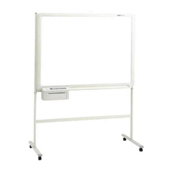
FEATURES BF-030S The board size is W1300mm × H920mm-large enough to show all the ideas that you discuss during your meetings, without any omissions. Information on the large screen can be copied immediately onto a sheet of A4/Letter paper. Those who attend a meeting can concentrate on the subject, as there is no need to waste time jotting down notes. -
Page 4: Product Features
PRODUCT FEATURES FRONT Board screen 50mm × 50mm gridded surface area Tray Printer Operation panel T-shaped stand Caster Printer cover REAR Expansion slot (for optional upgrades) T-shaped stand Optional accessory sold separately: ) ( PC interface board - to enable down- loading of board information from the BF-030S/W/035 to the PC... -
Page 5: Specifications
SPECIFICATIONS BF-035 BF-030W Item BF-030S W1800 × H920 mm (71 × 36 inch) W1300 × H920 mm (51-3/16 × 36 inch) W1300 × H920 mm (51-3/16 × 36 inch) Board surface size W1240 × H800 mm (48-7/8 × 34-3/4 inch) W1740 ×... -
Page 6: Control Functions
CONTROL FUNCTIONS BF-030S OPERATION PANEL PLUS BOARDFAX BF-030S FEED POWER ON PAPER OUT REPEAT COPY STOP OPEN POWER PAGE A Opening button ... Press this button to open the printer hatch when Two-surface reduction Two-surface reductia .. This is used when copying two pages of the replacing the thermal paper. -
Page 7: Maintenance/How To Store
BF-035 OPERATION PANEL PLUS BOARDFAX BF-035 POWER ON SCREEN PAGE-L REPEAT PAGE-R COPY SCREEN OPEN PAPER OUT POWER PAGE A Opening button ..Press this button to open the printer hatch F PAGE-L key ....Press this key to slide the panel to the left. (Press when replacing the thermal paper. -
Page 8: Handling Precautions
HANDLING PRECAUTIONS <FOR SAFE USE> 1. Avoid placing the machine in hot spots where it is exposed to direct sunlight or where an air conditioning duct. 2. When using sticky tape on the surface of the board screen, do not leave it on for a long time. Moreover, after removing it, wipe the screen clean. -
Page 9: Main-Board Setting Table
MAIN-BOARD SETTING TABLE 1. MAIN-board 1 Sections marked # are set with shorting pins. Model Type Switch Jumper setting Remarks panel 2 surfaces/standard/A4 BF-030S 2 surfaces/standard/letter 2 surfaces/wide/A4 BF-030W 2 surfaces/wide/letter 5 surfaces/standard/A4 BF-035S 5 surfaces/standard/letter 2. MAIN-board 2 ✽ Set with solder shorts. J7: BF-030/035 (PC) series 3. -
Page 10: Adjustment Modes
ADJUSTMENT MODES There are the following methods for entering each mode. (1) Adjustment 1: Switch on the power while holding down SW5. (2) Adjustment 2: Switch on the power while holding down SW1 and SW4. To end an adjustment mode, switch off the power and switch it back on without holding down any of the keys. (Test mode continues until the power is switched off.) Adjustment mode specifications Function summary... -
Page 11: Ccd Board Adjustment
CCD BOARD ADJUSTMENT 1. Initialization 1) Range setting of oscilloscope 100 mV/div. (for 10:1 probe) 20 mV/div. (for 10:1 probe) Time base 0.5 ms Coupling DC 2) Connect the probe to the test pin on the main board. The trigger source for Channel 3 coupling is AC. 3) GND position adjustment (See the figure on the right.) Immediately after the oscilloscope power is switched on, the ground position fluctuates easily, so... - Page 12 2) Slide the lens shade to adjust the amount of light so that the aperture peak waveform is flat, then secure the lens shade in place. (See the figure on the right.) Adjustment range (limit values) 2.6-3.4 V Adjustment standard 3.3 V 3.3V Be careful not to exceed the top limit of 3.8 V.
- Page 13 6. Optical axis alignment •As shown in the figure, enter a mark on the block vertical line and at a point 71 mm away from the black line. •Move the sheet until the mark moves to the left edge. 71mm (The vertical line is reflected in the center of the mirror.) •Move SCs 2 and 4 to make the waveform shown in the figure.
-
Page 14: Troubleshooting
TROUBLESHOOTING Item Trouble Cause Correction The power will not turn on and no 1. Check the breaker. 1. Power is not reaching the outlet. operation is available. (POWER-ON 2. Change the power cable. 2. Power cable defect LED will not light.) 3. - Page 15 Item Trouble Cause Correction Sheet sliding anomaly <Poor sliding 1. Sheet motor defect 1. Change the sheet motor. operation/abnormal sound> 2. Poor adjustment of timing belt 2. Adjust the motor mounting position tension and change the belt. 3. Disconnection of harness and poor 3.
-
Page 16: Disassembly
DISASSEMBLY 1.Board Main Unit Disassembly Decorative 1) Remove the frame cover unit. frame •Remove the two screws [M] and two screws [U] (three screws for 030). •Remove the main harness and the power relay Main unit harness. •Remove the frame cover unit. Back panel Back panel corner B... - Page 17 BF-035 •Remove the two screws [T] and remove both the top and bottom sheet guides. •Remove the four screws [B] and remove both angles. •Remove the two screws [G] and release the lever plate. •Remove the sheet paper tube on one side and wind Paper tube up the sheet.
- Page 18 5.Printer Disassembly 4.Removing Internal Parts 1) Remove the printer unit from the frame cover. Remove the main board. •Remove the four screws [O] and remove the printer •Remove the harnesses connected to the main unit from the frame cover. board. •Restrain the locking card spacer and remove the 2) Remove the printer rear cover.
- Page 19 6) Remove the printer frame. •Remove the two screws [R]. •Remove the printer frame from the printer cover. AC cord Switch panel Printer rear cover Sub-board Hinge plate (R) Printer frame Front cover 7) Remove the printer motor. •Remove the two screws [B] and remove the printer motor.
- Page 20 Binding Type PARTS NO. Specifications Surface Processing NOTES SCREW 951126510 M2.6 × 5 Round head MFZn I-C 035 only SCREW 951230610 M3 × 6 Bind MFZn I-C SCREW 951240620 M4 × 6 Bind MFZn I-C M4 × 45 Bind SCREW 951244510 MFZn I-C 035 only...
-
Page 21: Parts List
PARTS LIST Board unit BF-030S PARTS NO. PARTS NAME Q'TY NOTES AREA PRICE 714091390 Frame cover unit Printer unit No parts supply 714150500 Frame cover/lower Draves & Sheet unit No parts supply Board frame unit No parts supply 714512500 Back panel 714111600 Back panel corner B(vertical) M4 ×... - Page 22 Board unit BF-030W PARTS NO. PARTS NAME Q'TY NOTES AREA PRICE 714092390 Frame cover unit Printer unit No parts supply 714650500 Frame cover/lower Draves & Sheet unit No parts supply Board frame unit No parts supply 714912500 Back panel W 714111600 Back panel corner B(vertical) M4 ×...
- Page 23 Board unit BF-035 PARTS NO. PARTS NAME Q'TY NOTES AREA PRICE 714093390 Frame cover unit Printer unit No parts supply 714150500 Frame cover/lower Draves & Sheet unit No parts supply Board frame unit No parts supply 714512500 Back panel 714111600 Back panel corner B(vertical) M4 ×...
- Page 24 Frame cover unit BF-030S/W PARTS NO. PARTS NAME Q'TY NOTES AREA PRICE 714150100 Corner cover/uppre 714150200 Corner cover/R 714150300 Frame cover/upper Standard-type 714650300 Frame cover/upper Wide-type 714150400 Frame cover/side M4 × 10 P Tapping & Round head 953141010...
- Page 25 Frame cover unit BF-035 PARTS NO. PARTS NAME Q'TY NOTES AREA PRICE 714150100 Corner cover/uppre 714150200 Corner cover/R 714150300 Frame cover/upper 714204400 Frame cover/side 714203300 Urethene sponge M4 × 10 P Tapping & Round head 953141010...
- Page 26 Draves & Sheet unit BF-030S PARTS NO. PARTS NAME Q'TY NOTES AREA PRICE 714091190 Sheet frame assy 714520900 Sheet panel No parts supply 714722400 Endless sheet 714122000 Endless sheet UL only NORTH AMERICA 714180800 Sheet motor assy M3 × 6 3–point type 952530610...
- Page 27 Draves & Sheet unit BF-030W PARTS NO. PARTS NAME Q'TY NOTES AREA PRICE 714092190 Sheet frame assy W 714620900 Sheet panel No parts supply 714622400 Endless sheet 714122000 Endless sheet UL only NORTH AMERICA 714180800 Sheet motor assy M3 × 6 3–point type 952530610...
- Page 28 Draves & Sheet unit BF-035...
- Page 29 Draves & Sheet unit BF-035 PARTS NO. PARTS NAME Q'TY NOTES AREA PRICE 714093190 Sheet frame assy 714520900 Sheet panel No parts supply 714093290 White sheet assy 716758500 Sheet bearing 716758600 Sheet axis lower 714200100 Sheet roller bearing 716760500 Oilless bush 716758000 Spring plate 716758400...
- Page 30 Board frame unit BF-030S...
- Page 31 Board frame unit BF-030S PARTS NO. PARTS NAME Q'TY NOTES AREA PRICE 714510100 Board frame unit 714110306 Pipe frame No parts supply 714511500 Back panel corner A(horizontal) No parts supply 714410500 Back panel corner A(horizontal) No parts supply 714311705 Psition mirror plate/upper 714311806 Psition mirror plate/lower 714111900...
- Page 32 Board frame unit BF-030W...
- Page 33 Board frame unit BF-030W PARTS NO. PARTS NAME Q'TY NOTES AREA PRICE 714910100 Board frame unit 714610306 Pipe frame W No parts supply 714613300 Back panel corner AW(horizontal) No parts supply 714410600 Back panel corner AW(horizontal) No parts supply 714311705 Psition mirror plate/upper 714311806 Psition mirror plate/lower...
- Page 34 Board frame unit BF-035...
- Page 35 Board frame unit BF-035 PARTS NO. PARTS NAME Q'TY NOTES AREA PRICE Board frame unit 714110306 Pipe frame No parts supply 714511500 Back panel corner A(horizontal) No parts supply 714410500 Back panel corner A(horizontal) No parts supply 714311705 Psition mirror plate/upper 714311806 Psition mirror plate/lower 714111900...
- Page 36 Printer unit I BF-030/-035...
- Page 37 Printer unit I BF-030/-035 PARTS NO. PARTS NAME Q'TY NOTES AREA PRICE 714130200 Printer cover 714830200 Printer cover UL only NORTH AMERICA 714131800 Swich panel BF-030S/W 714831800 Swich panel BF-030S/W UL only NORTH AMERICA 714410100 Swich panel BF-035 714410200 Swich panel BF-035 UL only NORTH AMERICA 714411300 Swich sheet (BF-030S)
- Page 38 Printer unit II BF-030/-035...
- Page 39 Printer unit II BF-030/-035 PARTS NO. PARTS NAME Q'TY NOTES AREA PRICE 714330509 Printer frame 714130800 Intermediate gear 714330904 Thermal head mounting base 714131000 Head fixing collar 714131100 Head fixing spring 714131200 Thermal head spring 714331305 Lock base 714131400 Lock base collar 714131500 Lock spring 714131600...
- Page 40 T–shaped PARTS NO. PARTS NAME Q'TY NOTES AREA PRICE 714160109 Stand pipe Standart-type 714660109 Stand pipe W Wide-type 714160700 Joint cap/upper 714160800 Joint cap/lower 714091290 Caster pipe assy 714660400 Front caster 714660500 Back caster 954382010 Hexagonal button bolt 957281210 Flat washer 957380010 Spring washer...
- Page 41 Wall mounting PARTS NO. PARTS NAME Q'TY NOTES AREA PRICE 714112600 Pipe frame cap 714559302 Board plate 714559104 Upper bracket 714559203 Lower bracket M4 × 15 S Tapping Bind 953641530 M6 × 15 2–point type 952161530...
- Page 42 Packing BF-030/035(T-shaped stand type) 付属品在中 ACCESSORY...
- Page 43 Packing BF-030/035(T-shaped stand type) PARTS NO. PARTS NAME Q'TY NOTES AREA PRICE 714412400 Operation manual 030S only 714414500 Operation manual 030W only 714414600 Operation manual 035 only 714570700 Assembly intruction manual 714171300 Carton accessory 714171800 A Pad accessory 714171900 B Pad accessory 714173005 Dry–Eraser 714173900...
- Page 44 Packing BF-030/035(Wall mounting type) 付属品在中 ACCESSORY...
- Page 45 Packing BF-030/035(Wall mounting type) PARTS NO. PARTS NAME Q'TY NOTES AREA PRICE 714412400 Operation manual 030S only 714414500 Operation manual 030W only 714414600 Operation manual 035 only 714870700 Installation manual 714171300 Carton accessory 714171800 A Pad accessory 714171900 B Pad accessory 714170100 Fax paper(A4) A4 size...
-
Page 46: Wiring Diagram
WIRING DIAGRAM BF-030S/W... - Page 47 BF-035...
-
Page 48: Internal Connecting Function
Plunger Main board VS Puls motor CN109 Sheet Motor left Sheet Motor left Sheet Motor left Sheet Motor left +24V +24V Main board VS Plus motor +24V CN110 Sheet Motor right +24V Sheet Motor right +24V Sheet Motor right +24V... - Page 49 Main board VS PC board Sub board VS Themal Head CN111 CN111 CN403 THERMISTOR(Priner Head) THERMISTOR(Priner Head) STB1(Priner Head) STB2(Priner Head) STB3(Priner Head) CLK1 STB4(Priner Head) Head Clock Head Latch CLK2 Head Data Sub board VS Paper SW board CN404 Paper SW Paper SW Sub board VS SW board...
Need help?
Do you have a question about the COPY BOARD BF-030S and is the answer not in the manual?
Questions and answers