
Subscribe to Our Youtube Channel
Related Manuals for Advantech PPC-3151


Summary of Contents for Advantech PPC-3151
- Page 1 User Manual PPC-3151 Intel® Core i Processor Based Micro-Computer with a 15" Color TFT LCD Display...
- Page 2 No part of this manual may be reproduced, copied, translated or transmitted in any form or by any means without the prior written permission of Advantech Co., Ltd. Information provided in this manual is intended to be accurate and reliable. How- ever, Advantech Co., Ltd.
-
Page 3: Declaration Of Conformity
This product has passed the CE test for environmental specifications when shielded cables are used for external wiring. We recommend the use of shielded cables. This kind of cable is available from Advantech. Please contact your local supplier for ordering information. -
Page 4: Safety Instructions
The sound pressure level at the operator's position according to IEC 704-1:1982 is no more than 70 dB (A). DISCLAIMER: This set of instructions is given according to IEC 704-1. Advantech disclaims all responsibility for the accuracy of any statements contained herein. - Page 5 Battery Information Batteries, battery packs and accumulators should not be disposed of as unsorted household waste. Please use the public collection system to return, recycle, or treat them in compliance with the local regulations. PPC-3151 User Manual...
- Page 6 PPC-3151 User Manual...
-
Page 7: Table Of Contents
BIOS Setup Utility ................... 24 4.2.1 Entering BIOS Setup..............24 4.2.2 LCD Brightness Adjustment............25 4.2.3 COM5 Mode (RS422/485) Selection .......... 27 4.2.4 Wake up by LAN ................. 28 Appendix A RoHS List ...........31 RoHS List ....................32 PPC-3151 User Manual... - Page 8 PPC-3151 User Manual viii...
-
Page 9: Chapter 1 Overview
Chapter Overview This chapter gives background information on the PPC-3151 panel PC. Sections include: Introduction Specifications Dimensions... -
Page 10: Introduction
1 x PCIe x1 (standard configuration) Expansion Slots 1 x PCI (in accessory box) Additional 1 x Mini PCIe card slot Expansion Slots 1 x M.2 card slot (supported model: 22 x 42 mm, SATA interface) Win 7(32Bit/64Bit)/Win 8.1(64Bit)/Win 10(64Bit)/Linux PPC-3151 User Manual... -
Page 11: Power Specifications
CB, CCC, UL, BSMI 1.2.6 IP Grade Front Panel Dustproof IP65 and waterproof Note 1: Power consumption of PPC-3151 is shown as below: Test Software Test Configuration Test System Memory: 8G DDR4 2133 Burn-in 7.0 HDD: 2.5" 500G SATA III Win 7 (64bit) IO: COM Port RS232 loopback x 2, USB 3.0 x 4... -
Page 12: Dimensions
Dimensions Note! Screw specification: M4; hole depth is 8 mm for maximum. Use suitable mounting apparatus to avoid risk of injury. PPC-3151 User Manual... -
Page 13: Chapter 2 System Installation And Setup
Chapter System Installation and Setup Sections include: A Quick Tour Installation Procedures Replacing Memory Installing HDD Installing M.2 Installing Wireless LAN Installing Expansion Card Adjusting AT/ATX Functions Grounding Installing Hook ... -
Page 14: A Quick Tour
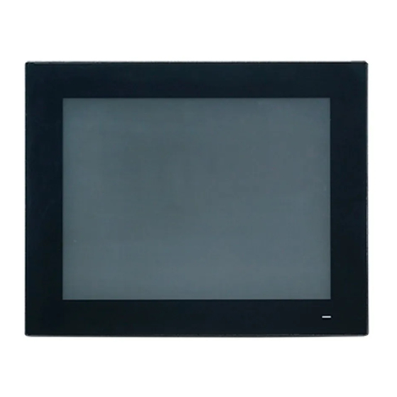
When the panel PC is placed on the desk, its front panel is shown as Figure 2.1. Figure 2.1: Front View Power status LED: Off (S5) Orange; Sleep (S3) Orange; On (S0) Blue. Figure 2.2: Side View PPC-3151 User Manual... -
Page 15: Figure 2.3: I/O Connectors
B: Line-out / Mic-in C: 4 x USB 3.0 D: 2 x Giga Ethernet ports E: VGA F: DP G: 2 x RS-232 H: DC power connector (9-32V) I: 1 x RS-422/485 J: Power switch K: Grounding screw PPC-3151 User Manual... -
Page 16: Installation Procedures
Connect mouse and keyboard to the I/O connector of the panel PC. Refer to Figure 2.3, C, USB. 2.2.3 Switching on the Panel PC Power switch is located at the lower right corner of the rear cover. Refer to Figure 2.3, J, Power switch. Note! Power cord and adapter are optional. PPC-3151 User Manual... -
Page 17: Installing Memory
Unfasten the screws marked with red circles (see below left figure). Pop-up the hook marked with a red oval (see below right figure) to remove the rear cover. Unfasten the screws indicated in the below left figure and take out the heatsink, then replace the memory. PPC-3151 User Manual... -
Page 18: Installing Hdd
VESA holder below left, then take out the HDD bracket below right. Take out 4 screws (see below) from the accessory box to secure the HDD onto the bracket, then replace and fix the HDD bracket. PPC-3151 User Manual... -
Page 19: Installing M.2
Unfasten the screws marked with red circles, and then fix M.2 to the location marked with a red rectangle. Note! Please note the pin direction when installing a M.2 device. Only 22 x 42mm M.2 device with a SATA interface is supported. PPC-3151 User Manual... -
Page 20: Installing Wireless Lan Card
The installation of a half-size card is shown as below. Take out copper cylinders and screws from the accessory box. PPC-3151 User Manual... - Page 21 Note the installation direction of cable end, screw caps and washers. To make the antenna installation easier, please firstly remove two brackets marked with the red rectangles, and then replace them when the instal- lation is completed. PPC-3151 User Manual...
- Page 22 Remove two plugs on the rear cover as shown in the below. Then replace the rear cover and install the antenna of wireless LAN card module Note! Advantech wireless LAN card module (PN: PPC-WLAN-A1E) is optional for you. PPC-3151 User Manual...
-
Page 23: Installing Expansion Card
You can adjust AT or ATX function by the internal switch indicated by the red rectan- gle without removing the rear cover. Grounding Grounding screw is marked with a red circle in below. It is recommended that the product with a capacitive screen should be properly grounded. PPC-3151 User Manual... -
Page 24: Installing Hook
Hook Installation Method Hook Place the PC into the cabinet and prepare the hook. Put the hook into the hook hole in the direction shown as above to hook the PC. Screw Fasten the screw to secure the PC. PPC-3151 User Manual... -
Page 25: Solo Quick Installation
Unfasten the two screws at the bottom as shown in below. Please refer to the below figure to place and push the panel PC into the opening on the wall, then the hook will secure the PC onto the wall. PPC-3151 User Manual... - Page 26 Note! It is recommended that the panel inlaid depth should be less than 2mm (0.079”) according to "Quick Installation Guide". In other circumstances, it is recommended that the panel inlaid depth should be less than 3mm (0.118”). PPC-3151 User Manual...
-
Page 27: Chapter 3 Jumper And Switch Settings
Chapter Jumper and Switch Settings Sections include: Jumpers and Connectors External COM Port & DIO Switch and Pin Assignments... -
Page 28: Jumpers And Connectors
Jumpers and Connectors CN12 CN22 CN18 Connector Function CN12 GPIO CN18 COM Pin9 power selection CN22 Power button AT/ATX selection Clear CMOS Icon Clear CMOS (1-2) Normal * Default * (2-3) Clear CMOS PPC-3151 User Manual... - Page 29 CN18 COM1/2 RI type selection (1-3)/(2-4) P9/P10 COM1/COM2 RI Default * (3-5)/(4-6) P11/P12 COM1/COM2 5V (7-9)/(8-10) P13/P14 COM1/COM2 12V CN12 Signal GPIO4 GPIO0 GPIO5 GPIO1 GPIO6 GPIO2 GPIO7 GPIO3 PPC-3151 User Manual...
-
Page 30: External Com Port Pin Assignments
BIOS. RS422 RS485 UART RS485 auto flow control COM5 supports RS485 auto flow control function. When enabling the RS485 auto control function, it will automatically drive RTS# pin to logic high or low for flow control. PPC-3151 User Manual... -
Page 31: Chapter 4 Software Setup
Chapter Software Setup Sections include: Installing Drivers BIOS Setup Utility... -
Page 32: Installing Drivers
When you install the system for the first time, please install the corresponding drivers in advance to make sure all the functions could run normally. Please select the driv- ers to be installed based on the OS you use. Please go to Advantech official website to get the latest versions of drivers: http://www.advantech.com.cn/ BIOS Setup Utility 4.2.1... -
Page 33: Lcd Brightness Adjustment
4.2.2 LCD Brightness Adjustment Select “System Agent(SA) Configuration” under "Chipset" tab. Then choose "Graphics Configuration" under “System Agent (SA) Configura- tion” item. PPS-3151S User Manual... - Page 34 Select "LCD Control" under “Graphics Configuration”. Select “Brightness Manual Control” under “Brightness Control”, and there will be 6 brightness options to choose. PPC-3151 User Manual...
-
Page 35: Com5 Mode (Rs422/485) Selection
4.2.3 COM5 Mode (RS422/485) Selection Select “NCT6106D Super IO Configuration” under “Advanced” tab. Then choose "Serial Port5 Configuration" under “NCT6106D Super IO Configu- ration” item. PPS-3151S User Manual... -
Page 36: Wake Up By Lan
Click “Serial Port 5 Configuration" item to choose the operating mode of COM5. 4.2.4 Wake up by LAN Select “PCH-IO Configuration” under "Chipset" tab. PPC-3151 User Manual... - Page 37 Set “Deep Sleep” as “Disabled”. Then set “Wake On By PCIE Wake” and “Wake on By LAN1 (219LM)” as “Enabled”. Save all the settings and exit. Then enter the OS. Right-click on “Computer” and select “Manage" to pop up “Computer Manage- ment”...
- Page 38 “Properties” to pop up “Intel(R) Ethemet” window. In “Intel(R) Ethemet” window, go to "Power Management" tab and check the boxes of "Work On Magic Packet", "Work On Pattern Match" and "Work On Magic Packet From Power Off State". PPC-3151 User Manual...
-
Page 39: Appendix A Rohs List
Appendix RoHS List... -
Page 40: Rohs List
RoHS List Dear Customer, Thanks for choosing Advantech Product, to comply with China Electronic Industry Standard SJ/T11364 which require Marking for the Restriction of the Use of Hazard- ous Substances in Electrical and Electronic Products, herein report to you product’s environmental protection as follows. - Page 41 PPC-3151 User Manual...
- Page 42 No part of this publication may be reproduced in any form or by any means, electronic, photocopying, recording or otherwise, without prior written permis- sion of the publisher. All brand and product names are trademarks or registered trademarks of their respective companies. © Advantech Co., Ltd. 2017...
Need help?
Do you have a question about the PPC-3151 and is the answer not in the manual?
Questions and answers