
Related Manuals for Advantech UNO-2484G V2


Summary of Contents for Advantech UNO-2484G V2
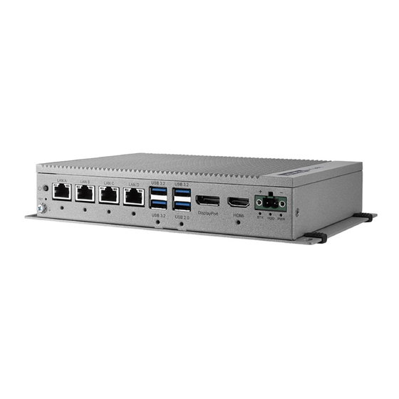
- Page 1 User Manual UNO-2484G V2 電腦 ® Intel Core™ i Standard-Size Automation Computer with 1 x GbE, 3 x 2.5 GbE, 2 x mPCIe, 1 x M.2 B-key, 1 x M.2 M-key, 1 x HDMI, 1 x DP, 1 x USB2.0, 3 x USB 3.2, 1 x USB TypeC, and...
- Page 2 No part of this manual may be reproduced, copied, translated, or transmitted in any form or by any means without the prior written permission of Advantech Co., Ltd. The information provided in this manual is intended to be accurate and reliable.
- Page 3 UNO2484GB5312603-T Product Warranty (2 years) Advantech warrants the original purchaser that each of its products will be free from defects in materials and workmanship for two years from the date of purchase. This warranty does not apply to any products that have been repaired or altered by persons other than repair personnel authorized by Advantech, or products that have been subject to misuse, abuse, accident, or improper installation.
- Page 4 This product has passed the CE test for environmental specifications when shielded cables are used for external wiring. We recommend the use of shielded cables. This type of cable is available from Advantech. Please contact your local supplier for ordering information.
- Page 5 This equipment is not suitable for use in locations where children are likely to be present. If the equipment is used in a manner not specified by the Advantech, the protec- tion provided by the equipment may be impaired. The equipment contains no user-serviceable parts. Do not open, Return to man- ufacturer for servicing.
- Page 6 Advantech for further information. Caution: Hot surface. Do not touch for Top Heatsink. DISCLAIMER: These instructions are provided according to IEC 704-1 standards. Advantech disclaims all responsibility for the accuracy of any statements contained herein. Consignes de sécurité Lire attentivement les instructions de sécurité.
- Page 7 – L'équipement est tombé et endommagé. – L'équipement présente des signes évidents de rupture. NE LAISSEZ PAS CET ÉQUIPEMENT DANS UN ENVIRONNEMENT OU LA TEMPÉRATURE DE STOCKAGE PEUT ÊTRE INFÉRIEURE À -40° C (-40° F) OU BIEN SUPÉRIEURE À 85° C (185° F). CECI POURRAIT ENDOMMAGER L'EQUIPEMENT.
- Page 8 設備曾暴露在過度潮濕環境中使用; 設備無法正常工作,或您無法透過用戶手冊來正常工作; 設備摔落或損壞; 設備有明顯外觀損; 請勿將設備儲存在超出建議溫度範圍的環境,即不要低於 -40°C(-40°F)或 高於 85°C(185°F),否則可能會造成設備損壞。 注意:若電池更換不正確,將有爆炸危險。因此,只可以使用製造商推薦的同一 種或者同等型號的電池進行替換。請按照製造商的指示處理舊電池。 根據 IEC 704‐1:1982 規定,操作員所在位置音量不可高於 70 分貝。 限制區域:請勿將設備安裝於限制區域使用。 免責聲明:請安全訓示符合 IEC 704‐1 要求。研華公司對其內容之準確性不承 擔任何法律責任。 消费者若使用电源适配器供电,则应购买配套使用获得 CCC 认证并满足标准要 求的电源适配器。 警告:機殼高溫。請勿在使用過程中觸碰上方散熱鰭片。 UNO-2484G_V2 User Manual viii...
-
Page 9: Table Of Contents
Chapter Hardware Functionality.......7 Introduction ....................8 Figure 2.1 Front Panel of UNO-2484G V2........8 Figure 2.2 Rear Panel of UNO-2484G V2 ........8 Serial Communication Ports..............8 2.2.1 COM Port Interfaces (COM1, COM2, COM3, COM4) ....8 2.2.2 Power Connector ................8 2.2.3... - Page 10 Open/Close the Rear Cover..............16 3.3.1 Installing NVME Module ............. 16 3.3.2 Installing miniPCIe Module ............19 3.3.3 Installing M.2 B Key Module ............21 3.3.4 Installing M.2 B key 2242 Module..........24 3.3.5 Installing 2.5” SSD Module ............27 3.3.6 Installing Expansion Kit...............
- Page 11 Figure 4.45PCH-IO Configuration – 2......... 67 Figure 4.46PCH-IO Configuration – 3......... 67 Figure 4.47PCH-IO Configuration - 4 ......... 68 Figure 4.48PCH-IO Configuration - 5 ......... 68 Security ....................72 Figure 4.49Security..............72 Figure 4.50Secure Boot - 1............72 Figure 4.51Secure Boot – 2............73 Boot......................
- Page 12 UNO-2484G_V2 User Manual...
-
Page 13: Chapter 1 Overview
Chapter Overview This chapter provides an overview of UNO-2484G V2 specifications. Introduction Safety Precautions Accessories... -
Page 14: Introduction
Fieldbus, as well as I/O and peripheral modules. The UNO-2484G V2 also has one M.2 B key, one M.2 M key for convenient expan- sion. This allows the UNO-2484G V2 to be integrated with high speed Wi-Fi 6, 5G,... -
Page 15: Packing List
Packing List Please refer to below packing list: UNO-2484G V2 1 x plug-in block for power wiring Simplified Chinese manual Quick Start Guide Warranty card Thermal pad M.2 M key module: 1990038768N010 Thermal pad M.2 B key module: 1990038769N010 ... -
Page 16: I/O Interfaces
Table 1.5: Certification Certification CE, FCC, UL, CCC, BSMI 1.4.6 Extension Kit (Optional) UNO-2484G V2 features a modularized design. Advantech offers two optional 2nd stack extension kits for users to expand the functionality using an Advantech iDoor module. UNO-2484G_V2 User Manual... -
Page 17: Dimensions
Dimensions 40 x 140 x 200 mm (2.76 x 5.51 x 7.87 in) Figure 1.1 UNO-2484G V2 Dimensions Figure 1.2 UNO-2484G V2 Dimensions (with optional extension kit) UNO-2484G_V2 User Manual... - Page 18 UNO-2484G_V2 User Manual...
-
Page 19: Chapter 2 Hardware Functionality
Chapter Hardware Functionality This chapter explains how to setup the UNO-2484G V2’s hard- ware functions, including con- necting peripherals and setting switches and indicators. Introduction UNO-2484G V2 Interface LAN/Ethernet Connector Power Connector USB Connector RTC Battery ... -
Page 20: Introduction
2.2.2 Power Connector UNO-2484G V2 comes with a Phoenix connector that carries 10 - 36 V external power input, and features reversed wiring protection. Therefore, the system will not accrue damage from reversed polarity of ground lines and power lines. (Please refer to User Manual - Appendix A.1 for pin assignments) -
Page 21: Usb Connector
2.2.4 USB Connector UNO-2484G V2 features 3 x USB ports for Rev. 3.2 specifications and 1 x USB 2.0port. The USB connectors support plug-and-play and hot-swap-ping functionality for external devices. Additionally, this can be enabled/disabled in the BIOS menu. (Please refer to User Manual- Appendix A.3 for pin assignments.) 2.2.5... -
Page 22: M-Key Connector
This product offers two antenna mounting holes covered by pre-cut holes for users to install an antenna kit for LTE or wireless functions. Base Unit’s Internal Connectors Figure 2.3 Diagram of Connector Locations on UNO-2484G V2 (Top Side) UNO-2484G_V2 User Manual... - Page 23 Figure 2.4 Diagram of Key Components Location on UNO-2484G V2 (Bottom Side Table 2.1: Connectors and Jumpers Category Label Function DCIN1 Power-in connector HDMI1 HDMI connector DisplayPort connector TYPEC1 TYPE-C connector USB3C1 USB 3.2 x2 Connector USB3C2 USB 3.2+2.0 Connector...
- Page 24 Table 2.1: Connectors and Jumpers COM56 Serial port pin header MPCIE1 MiniPCIe Connector MPCIE2 MiniPCIe Connector NVME1 M.2 M key for 2280 Connector Internal M2_B1 M.2 B key for 2242/3052 Connector GPIO1 GPIO interface SIM1 Nano SIM slot for M2_B1 PSON1 AT/ ATX setting UNO-2484G_V2 User Manual...
-
Page 25: Chapter 3 Initial Setup
Chapter Initial Setup This chapter explains the process for initializing the UNO-2484G V2. Chassis Grounding Connect the Power Supply Open/Close the Rear Cover Hard Disk Installation Extension Kit Installation... -
Page 26: Chassis Grounding
Chassis Grounding The UNO-2484G V2 provides adequate EMI protection and a stable grounding base. Moreover, an easy-to-connect chassis grounding point is also provided. Figure 3.1 Chassis Grounding Connection Cabinet/rack system Installation: Connect the cabinet/Rack system to the earth/ground. Install the UNO device into the cabinet/Rack system without I/O or power cables. -
Page 27: Connect The Power Supply
Connect the Power Supply The UNO-2484G V2 is intended to be supplied by an approved power adapter or DC power source. This adapter is rated at 10 - 36dc, and has a Tmax of 60° C (140° F). If you need further assistance or information, please contact Advantech. - Page 28 Open/Close the Rear Cover The rear cover can be opened in order to install a mPCIe/ NVME/ M.2 module, SSD, or HDD, or to adjust the switch settings. 3.3.1 Installing NVME Module Remove the six screws (PN:1930001361*6pcs) on the rear cover. UNO-2484G_V2 User Manual...
- Page 29 Insert NVME card at the location: “NVME1” and secure it with the provided screw (PN: 19350304A0*1pcs). Paste the thermal pad (PN: 1990038768N010*1pcs) on the Aluminum block from the accessory bag. UNO-2484G_V2 User Manual...
- Page 30 Close the rear cover and re-attach the six screws (PN:1930001361*6pcs) back. UNO-2484G_V2 User Manual...
- Page 31 3.3.2 Installing miniPCIe Module Remove the six screws (PN:1930001361*6pcs) on the rear cover. UNO-2484G_V2 User Manual...
- Page 32 Insert miniPCIe card at the location: “mPCIE1” or “mPCIE2” and secure it with the provided screw (PN: 1930000198*1pcs). Close the rear cover and re-attach the six screws back (PN:1930001361*6pcs). UNO-2484G_V2 User Manual...
- Page 33 3.3.3 Installing M.2 B Key Module Remove the six screws (PN:1930001361*6pcs) on the rear cover. UNO-2484G_V2 User Manual...
- Page 34 Remove the pre-assy iron part (PN:1960102502T000*1pcs) and the screw. (PN:19350304A0*1pcs) Insert the M.2 2252 module and secure it with the provided screw (PN: 19350304A0*1pcs). UNO-2484G_V2 User Manual...
- Page 35 Paste the thermal pad (PN: 1990038769N010*1pcs), on the Aluminum block from the accessory bag. Close the rear cover and re-attach the six screws back (PN:1930001361*6pcs). UNO-2484G_V2 User Manual...
- Page 36 3.3.4 Installing M.2 B key 2242 Module Remove the six screws (PN:1930001361*6pcs) on the rear cover. UNO-2484G_V2 User Manual...
- Page 37 Insert the M.2 2242 module and secure it with the provided screw (PN: 19350304A0*1pcs). Paste the thermal pad (PN: 1990038769N010*1pcs), on the Aluminum block from the accessory bag. UNO-2484G_V2 User Manual...
- Page 38 Close the rear cover and re-attach the six screws back (PN:1930001361*6pcs). UNO-2484G_V2 User Manual...
- Page 39 3.3.5 Installing 2.5” SSD Module Remove the six screws (PN:1930001361*6pcs) on the rear cover. UNO-2484G_V2 User Manual...
- Page 40 Remove SSD bracket (PN:1960084377N000*1pcs) and screws (PN:1930008481*4pcs). UNO-2484G_V2 User Manual...
- Page 41 Assemble the SSD on the bracket with screws (PN:1930001361*4pcs). Assemble the SSD with bracket on the system slide rail. UNO-2484G_V2 User Manual...
- Page 42 Re-attach the SSD bracket with screws (PN:1930008481*4pcs). Close the rear cover and re-attach the six screws back (PN:1930001361*6pcs). UNO-2484G_V2 User Manual...
- Page 43 3.3.6 Installing Expansion Kit Remove the six screws (PN:1930001361*6pcs) and the rubbers (PN:1990038767S000*2pcs) on the rear cover. UNO-2484G_V2 User Manual...
- Page 44 Assemble the second stack with screws (PN:1930001361*6pcs). UNO-2484G_V2 User Manual...
- Page 45 Close the rear cover and re-attach the six screws (PN:1930001361*6pcs) and the rubbers (PN:1990038767S000*4pcs). UNO-2484G_V2 User Manual...
- Page 46 UNO-2484G_V2 User Manual...
- Page 47 Chapter BIOS Operations...
- Page 48 The Setup Utility uses a number of menus for making changes and turning the specific features on or off. This chapter describes the basic navigation of the UNO-2484G V2 setup screens Figure 4.1 Main setup screen AMI BIOS ROM has a built-in Setup program that allows users to modify the basic system configuration.
- Page 49 4.2.2 Advanced BIOS Features Setup Select the Advanced tab from the UNO-2484G V2 setup screen to enter the Advanced BIOS setup screen. You can select any of the items in the left frame of the screen, such as CPU configuration, to go to the sub menu for that item. You can dis- play an Advanced BIOS Setup option by highlighting it using the keys.
- Page 50 Figure 4.3 Advanced BIOS features setup screen 4.2.2.1 CPU Configuration Figure 4.4 CPU configuration - 1 UNO-2484G_V2 User Manual...
- Page 51 Figure 4.5 CPU configuration - 2 C6DRAM To enable or disable moving DRAM contents to PRM memory when CPU is under C6 state. CPU Flex Ration Override To enable or disable CPU Flex Ration Override CPU Flex Ratio Settings ...
- Page 52 4.2.2.2 Power & Performance Figure 4.6 Power & Performance-1 Figure 4.7 CPU - Power Management Control-1 UNO-2484G_V2 User Manual...
- Page 53 Figure 4.8 CPU - Power Management Control-2 CPU Power Management Control Figure 4.9 View/configure Turbo option -1 – Intel(R) Speedstep(tm) Allows more than two frequency ranges to be supported. UNO-2484G_V2 User Manual...
- Page 54 – Intel(R) Speed Shift Technology To enable or disable Intel(R) Speed Shift Technology support. Enabling will expose the CPPC v2 interface to allow for hardware controlled P-state. – HDC Control This option allows HDC configuration. Disabled: Disable HDC. Enabled: Can be enabled by OS if OS native support is available. Turbo mode.
- Page 55 Config TDP Configurations Figure 4.11 Config TDP Configurations – Enable Configurable TDP Applies TDP initialization settings based on non-cTDP or cTDP. Default is 1: Applies to cTDP; if 0 then applies non-cTDP and BIOS will bypass cTDP ini- tialztion flow. –...
- Page 56 – Power Limit 1 Time Window Power Limit 1 Time Window value in seconds. The value may vary from 0 to 128. 0 = default value (28 sec for Mobile and 8 sec for Desktop). Defines time window which TDP value should be maintained. ConfigTDP Turbo Activation Ratio –...
- Page 57 Figure 4.12 GT – Power Management Control – Maximum GT Frequency Maximum GT frequency limited by the user. Choose between 100MHz (RPN) and 1300MHz (RPO). Value beyond the range will be clipped to min/max supported by SKU. Figure 4.13 Disable Turbo GT Frequency UNO-2484G_V2 User Manual...
- Page 58 Disable Turbo GT Frequency Enabled: Disables Turbo GT frequency is not limited. – AMT Configuration ® Configure Intel Active Management Technology Parameters. – Firmware Update Configuration 4.2.2.3 PCH-FW Configuration Figure 4.14 PCH-FW Configuration -1 UNO-2484G_V2 User Manual...
- Page 59 Figure 4.15 PCH-FW Configuration - 2 USB Provisioning of AMT Enable/Disable of ANT USB Provisioning. MAC Pass Through Enable/Disable MAC Pass Through function. Figure 4.16 CIRA Configuration UNO-2484G_V2 User Manual...
- Page 60 CIRA Configuration Configure Remote Assistance Process parameters. – Active Remote Assistance Process – Trigger CIRA boot – Note: Network Access must be activated first from MEBx Setup. ASF Configuration Configure Alert Standard Format parameters. Figure 4.17 ASF Configuration PET Progress ...
- Page 61 Figure 4.18 Secure Erase configuration Secure Erase Configuration Secure Erase configuration menu. Secure Erase mode – Change Secure Erase module behavior: Simulated: Performs SE flow with- out erasing SSD. Real: Erase SSD. – Force Secure Erase Force Secure Erase on next boot. UNO-2484G_V2 User Manual...
- Page 62 Figure 4.19 OEM Flags Settings OEM Flags Settings Configure OEM flags. – MEBx Hotkey Pressed MEBx Selection Screen – OEMFlag Bit 2: Enable MEBx selection screen with 2 options: press 1 to enter ME Configuration Screens. Press 2 to initiate a remote connection. Note: Network Access must be activated from MEBx Setup for this screen to be displayed.
- Page 63 Figure 4.20 MEBx Resolution settings Non-UI Mode Resolution Resolution for non-UI text mode. UI Mode Resolution Resolution for UI text mode. Graphics Mode Resolution Resolution for graphic mode. UNO-2484G_V2 User Manual...
- Page 64 Figure 4.21 Firmware Update Configuration-1 Figure 4.22 Firmware Update Configuration-2 Firmware Update Configuration Configure Management Engine Technology Parameters. – Me FW Image Re-Flash Enable/ Disable ME FW Image Re-Flash function. UNO-2484G_V2 User Manual...
- Page 65 – FW Update Enable/ Disable ME FW Image update function. Trusted Computing Figure 4.23 Trusted Computing-2 – SHA-1 PCR Bank Enable or Disable SHA-1 PCR Bank. SHA256 PCB Bank – Enable or Disable SHA-256 PCR Bank. – Pending Operation Schedule an Operation for the Security Device.
- Page 66 Figure 4.24 ACPI Setting -1 Figure 4.25 ACPI Setting - 2 ACPI Settings System ACPI Parameters. – Serial Port 2 Configuration ►COM2 Uart mode setting RS232/RS22/RS485 mode. UNO-2484G_V2 User Manual...
- Page 67 – Enable ACPI Auto Configuration Default is disabled. – Enable Hibernation Enable or disable System ability to Hibernate (OS/S4 Sleep State). This option may not be effective with some operating systems. ACPI Sleep State – Select the highest ACPI sleep state the system will enter when the SUS- PEND button is pressed.
- Page 68 Figure 4.27 NCT61260 Super IO Configuration – Super IO Chip NCT61260 – Serial Port 1 Configuration Set Parameters of Serial Port 1 (COMA). ►Serial Port Enable or Disable Serial Port (COM). ► COM1 Uart mode setting RS232/ RS422/ RS485 mode. –...
- Page 69 ►Serial Port Enable or Disable Serial Port (COM). – Serial Port 6 Configuration Set Parameters of Serial Port 6 (COMF). ►Serial Port Enable or Disable Serial Port (COM). Figure 4.28 H/W Monitor Configuration-1 H/W Monitor Configuration Monitor hardware status. –...
- Page 70 Figure 4.29 S5 RTC Make Settings -1 Figure 4.30 S5 RTC Make Settings -2 S5 RTC Make Settings Enable system to wake from S5 using RTC alarm – Wake System from S5 Enable or disable System wake on alarm event. Select FixedTime, system UNO-2484G_V2 User Manual...
- Page 71 will wake on the hr::min::sec specified. Select DynamicTime, System will wake on current time + Increase minute(s). Figure 4.31 USB Configuration -1 Figure 4.32 USB Configuration-2 USB Configuration USB Configuration Parameters. UNO-2484G_V2 User Manual...
- Page 72 – Legacy USB Support Enable Legacy USB Support. AUTO option disable legacy support if no USB devices are connected. DISABLE option will keep USB devices available only for EFI applications. – XHCI Hand-off – This is a workaround for OS without XHCI hand-off support. The XHCI own- ership change should be claimed by XHCI driver.
- Page 73 Figure 4.34 Network Stack Configuration - 2 Network Stack Configuration Network Stack Settings. Network Stack – Enable/ Disable UEFI Network Stack – IPv4 PXE Support Enable/ Disable IPv4 PXE boot support. If disabled, IPv4 PXE boot support will not be available. IPv4 HTTP Support –...
- Page 74 Figure 4.35 CSM Configuration – 1 Figure 4.36 CSM Configuration - 2 CSM configuration CSM Configuration: Enable/ Disable, Option ROM execution settings, etc. CSM Support – Enable/ Disable CSM Support. UNO-2484G_V2 User Manual...
- Page 75 Figure 4.37 NVMe Configuration -1 Figure 4.38 NVMe Configuration-2 NVMe Configuration NVMe Device Option Settings. UNO-2484G_V2 User Manual...
- Page 76 Chipset Figure 4.39 Chipset Figure 4.40 System agent (SA) configuration - 1 System Agent (SA) Configuration System Agent (SA) Parameters. UNO-2484G_V2 User Manual...
- Page 77 Figure 4.41 System agent (SA) Configuration - 2 Graphics Configuration Graphics Configuration. Primary Display – Select which of IGFX/PEG/PCI Graphics device should be Primary Display. Figure 4.42 VMD setup menu UNO-2484G_V2 User Manual...
- Page 78 VMD setup menu VMD configuration settings. – Enable VHD controller Enable/ disable to VMD controller. Figure 4.43 System Agent (SA) Configuration - 3 Figure 4.44 PCH-IO Configuration - 1 UNO-2484G_V2 User Manual...
- Page 79 PCH-IO Configuration PCH Parameters. Figure 4.45 PCH-IO Configuration – 2 PCI Express Configuration PCI Express Configuration settings. Figure 4.46 PCH-IO Configuration – 3 UNO-2484G_V2 User Manual...
- Page 80 Figure 4.47 PCH-IO Configuration - 4 mPCIE1: Control the PCI Express Root Port. PCIe speed: Configure PCIe Speed. mPCIE2: Control the PCI Express Root Port. PCIe speed: Configure PCIe Speed. Figure 4.48 PCH-IO Configuration - 5 UNO-2484G_V2 User Manual...
- Page 81 SATA and RST Configuration SATA Device Options Settings. – SATA Controller(s) Enable/ Disable SATA Device. – SATA Mode Selection Determines how SATA controller(s) operate. SATA Controller Speed – Indicates the maximum speed the SATA controller can support. – Topology Identify the SATA Topology if it is Default or ISATA or Flex or DirectConnect or M2.
- Page 82 USB PD0 Programming Select “Enabled” if Port Disable Override functionality is used. USB Overcurrent Select “Disabled” for pin-based debug. If pin-based debug is enabled but USB overcurrent is not disabled, USB DbC does not work. USB Overcurrent Lock ...
- Page 83 Onboard LAN1 Controller Select to Enable or Disable Onboard LAN1 Controller. LAN1 PXE OpROM: Enable or disable boot option for LAN1 Controller. Wake on LAN Enable: Enable or disable integrated LAN to wake the system. Onboard LAN2 Controller Enable or disable boot option for LAN2 Controller.
-
Page 84: Security
Security Figure 4.49 Security Figure 4.50 Secure Boot - 1 Administrator Password Set Administrator Password. UNO-2484G_V2 User Manual... - Page 85 Security Boot Secure Boot feature is Active if Secure Boot is Enabled. Platform Key (PK) s enrolled and the System is in User mode. The mode change requires platform reset. Secure Boot Mode Secure Boot mode options: Standard or Custom. In Custom mode, Secure Boot Policy variables can be configured by a physically present user without full authentication.
-
Page 86: Boot
Boot Figure 4.52 Boot Boot Configuration – Setup Prompt Timeout Number of seconds to wait for setup activation key. 65535(0xFFFF) means indefinites waiting. – Bootup NumLock State Select the keyboard NumLock state. – Quiet Boot Enables or disables Quiet Boot option. Boot Priorities ... -
Page 87: Save & Exit
Save & Exit Figure 4.53 Save & Exit Save Options Save Changes and Reset Exit system setup after saving the changes. Discard Changes and Exit Exit system setup without saving any changes. Save Changes and Reset Reset the system after saving the changes. - Page 88 UNO-2484G_V2 User Manual...
-
Page 89: Appendix A System Settings/Pin Assignments
Appendix System Settings/Pin Assignments... -
Page 90: Power Connector (Dcin1)
Power Connector (DCIN1) Table A.1: Power Connector Pin Assignments Signal Description Power IN V+ 10 - 36 V Power IN V- (GND) Clear CMOS Function (CMOS1) Table A.2: Clear CMOS Function (CMOS1) CMOS1 CMOS Clear Function Description This jumper is used to select CMOS Clear Enable/Disable (2-3) Enable (Clear CMOS) (1-2) -
Page 91: Usb Connector (Usb3C1/Usb3C2)
USB Connector (USB3C1/USB3C2) A.3.1 USB 2.0 Connector Table A.3: USB Pin Assignments Signal Name Description VBUS Power USB2.0 differential pair Ground for power return A.3.2 USB 3.2 Connector Table A.4: USB Pin Assignments Signal Name Description VBUS Power USB2.0 differential pair Ground for power return StdA_SSRX- SuperSpeed receiver differential pair... -
Page 92: Hdmi Connector (Hdmi1)
HDMI Connector (HDMI1) Table A.5: HDMI Port Adapter Cable Pin Assignments Signal Name TMDS1_a_P0 TMDS1_a_N0 TMDS1_a_P1 TMDS1_a_N1 TMDS1_a_P2 TMDS1_a_N2 TMDS1_CLK_a_P TMDS1_CLK_a_N TMDS1_DDCCLK TMDS1_DDCDAT TMDS1_HPD UNO-2484G_V2 User Manual... -
Page 93: M.2 B-Key Connector (M2_B1)
M.2 B-Key Connector (M2_B1) Table A.6: M.2 B key Connector Pin Assignments Signal Name Signal Name +V3.3_SB_M2_B1 +V3.3_SB_M2_B1 +V3.3_SB_M2_B1 M2_LTE_PWR_OFF# USB2_PCH_M1_B1_D_P M2_LTE_W1_DISABLE_N USB2_PCH_M1_B1_D_N +V3.3_SB_M2_B1 M2_PCIE_DIS M2_USB_DET +V3.3_SB_M2_B1 +V3.3_SB_M2_B1 M2_LTE_W2_DISABLE_N USB3_PCH_M2_B1_RX_N M2_SIM1_RESET USB3_PCH_M2_B1_RX_P M2_SIM1_CLK M2_SIM1_DATA USB3_PCH_M2_B1_TX_N M2_SIM1_PWR USB3_PCH_M2_B1_TX_P PCIE_USB M2_SIM2_DET SATA_PCH_M2_B1_RX_P SATA_PCH_M2_B1_RX_N SATA_PCH_M2_B1_TX_N SATA_PCH_M2_B1_TX_P... -
Page 94: M.2 M-Key Connector (Nvme1)
Table A.6: M.2 B key Connector Pin Assignments +V3.3_SB_M2_B1 +V3.3_SB_M2_B1 M.2 M-Key Connector (NVME1) UNO-2484G_V2 User Manual... - Page 95 Table A.7: M.2 B key Connector Pin Assignments Signal Name Signal Name +V3.3_SB_NVME1 +V3.3_SB_NVME1 PCIE_CPU_M2_M1_RX_N4 PCIE_CPU_M2_M1_RX_P4 PCIE_CPU_M2_M1_TX_N4 +V3.3_SB_NVME1 PCIE_CPU_M2_M1_TX_P4 +V3.3_SB_NVME1 +V3.3_SB_NVME1 PCIE_CPU_M2_M1_RX_N3 +V3.3_SB_NVME1 PCIE_CPU_M2_M1_RX_P3 PCIE_CPU_M2_M1_TX_N3 PCIE_CPU_M2_M1_TX_P3 PCIE_CPU_M2_M1_RX_N2 PCIE_CPU_M2_M1_RX_P2 PCIE_CPU_M2_M1_TX_N2 PCIE_CPU_M2_M1_TX_P2 PCIE_CPU_M2_M1_RX_N1 PCIE_CPU_M2_M1_RX_P1 PCIE_CPU_M2_M1_TX_N1 PCIE_CPU_M2_M1_TX_P1 PCIE_REQ# CLK100M_PCH_M2_M1_K_N PCIE_WAKE# CLK100M_PCH_M2_M1_K_P SUSCLK PEDET +V3.3_SB_NVME1 +V3.3_SB_NVME1...
-
Page 96: Mpcie Connector (Minipcie1/2)
mPCIe Connector (MINIPCIE1/2) Table A.8: mPCIe Connector Pin Assignments Signal Name Signal Name PCIE_WAKE# +V3.3_MINI +V1.5 PCIEX1_CLKREQ0# CLK100M_PCIEX1_D0- CLK100M_PCIEX1_D0+ WIFI_DISABLE# MINI_PLTRST# SATA0_RX+ +V3.3_MINI SATA0_RX- +V1.5 SATA0_TX- SATA0_TX+ USB2_MPCI_P8- USB2_MPCI_P8+ +V3.3_MINI +V3.3_MINI MPCIE_PWRSEL +V1.5 MSATA#_z_PCIE_SEL +V3.3_MINI UNO-2484G_V2 User Manual... -
Page 97: Com Port Rs232/422/485 Settings
COM Port RS232/422/485 Settings Table A.9: COM Port RS232/422/485 Settings RS232 RS422 RS485 UNO-2484G_V2 User Manual... -
Page 98: Lan1/2/3/4 Rj45 Connector
LAN1/2/3/4 RJ45 Connector Table A.10: LAN1/2/3/4 RJ45 Connector RJ45 Pin Signal Description MDI0+ In BASE-T: Media-dependent interface[0]: 1000BASE-T: In MDI configuration, MDI[0]+/- corresponds to BI_DA+/- and in MDI-X configuration MDI[0]+/- corre- sponds to BI_DB+/-. MDI0- 10BASE-T and 100BASE-TX: In MDI configuration, ... -
Page 99: Gpio Port (Gpio1)
A.10 GPIO Port (GPIO1) The GPIO port can connect to DB9 connector for extension module. Table A.12: GPIO Port (GPIO1) Signal Name GPIO0 GPIO1 GPIO2 GPIO3 GPIO4 GPIO5 GPIO6 GPIO7 UNO-2484G_V2 User Manual... -
Page 100: Dp Connector (Dp1)
A.11 DP Connector (DP1) Table A.13: Display Port Adapter Cable Pin Assignments Signal Name DP0_z_D0+ DP0_z_D0- DP0_z_D1+ DP0_z_D1- DP0_z_D2+ DP0_z_D2- DP0_z_D3+ DP0_z_D3- DP0_AUX_EN# DP0_CONFIG DP0_AUX_P DP0_AUX_N DP0_z_HPD +V3.3 UNO-2484G_V2 User Manual... -
Page 101: Type-C Connector (Typec1)
A.12 Type-C Connector (TYPEC1) TYPEC1 GND1 GND4 SSTXP1_1 SSRXP1_2 SSTXN1_1 SSRXN1_2 A1A2A3A4A5A6A7A8A9A10A11A12 VBUS_1 VBUS_4 B9 B7 B6 B4 SBU2 B11B10 B8 B5 B3B2 SBU1 VBUS_2 VBUS_3 SSTXN2_2 SSRXN2_1 SSTXP2_2 SSRXP2_1 GND3 GND2 USB_24H <Characteristic> Table A.14: mPCIe Connector Pin Assignments Signal Name Signal Name USBC_TXP0_CON... -
Page 102: At/Atx Setting (Pson1)
A.13 AT/ATX Setting (PSON1) PSON1 can be used for AT/ATX setting. The default setting is ATX mode. See the fol- lowing table for jumper configuration. Table A.15: AT/ATX Setting (PSON1) Default A.14 DC in Setting (DCOUT1) DCOUT1 can be used for iDoor module. The power input follow iDoor module speci- fication. -
Page 103: Slide Switch Setting (Sw1)
A.15 Slide Switch Setting (SW1) SW1 can be used for 5G module. The slide switch on the right hand side is on. The default setting of pin1~pin4 is on, and please follow the 5G module requirement for the slide switch setting A.16 Remote power Setting(FP1) FP1 can be used for iDoor module to connect power. - Page 104 No part of this publication may be reproduced in any form or by any means, such as electronically, by photocopying, recording, or otherwise, without prior written permission from the publisher. All brand and product names are trademarks or registered trademarks of their respective companies. © Advantech Co., Ltd. 2023...
Need help?
Do you have a question about the UNO-2484G V2 and is the answer not in the manual?
Questions and answers