Table of Contents
Advertisement
Quick Links
Uninterruptible power supply of 8 IP cameras (52 V DC)
Uninterruptible power supply of the recorder (12 V DC)
Switch 10 ports
8 PoE ports 10/100 Mb/s, (data and power supply)
2 ports 10/100 Mb/s (UpLink)
Long Range mode (up to 250m)
30 W for each PoE port, supports devices complaint
with the IEEE802.3af/at (PoE+) standard
Approximate backup time: 3h 15min
CONTENTS
2.2
S108-BR
S108-BR 10-port switch with buffer power supply
for 8 IP cameras and recorder
Edition: 4 from 25.09.2019
Supercedes the edition: 3 from 14.02.2019
Features
:
Example of use.
1
v1.2
LED indication
Metal enclosure - color white RAL 9003
with space for two 17 Ah/12 V battery
Supports auto-learning and auto-aging of
MAC addresses (1K size)
warranty - 2 year from the production date
PL
EN**
Advertisement
Table of Contents

Related Manuals for Pulsar S108-BR


Summary of Contents for Pulsar S108-BR
-
Page 1: Table Of Contents
S108-BR v1.2 S108-BR 10-port switch with buffer power supply for 8 IP cameras and recorder Edition: 4 from 25.09.2019 Supercedes the edition: 3 from 14.02.2019 EN** Features Uninterruptible power supply of 8 IP cameras (52 V DC) LED indication ... -
Page 2: Technical Description
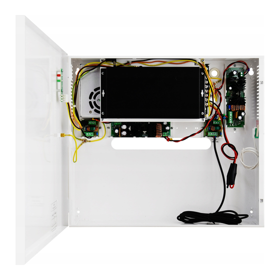
The switch is housed in a metal enclosure (color RAL 9003) which can accommodate a two 17 Ah/12 V batteries. The enclosure features a micro switch tamper indicating door opening (front panel). The S108-BR is fitted with two LEDs on the front panel (red LED –... -
Page 3: Description Of Components And Connectors
1.3 Description of components and connectors. Fig. 2. The enclosure view. Table 1. ( See Fig . 2) Component No. Description (Fig. 2) Switch PoE Switch mode buffer power supply unit DC/DC50SD converter DC/DC52230 converter Output filter Tamper – micro switch (terminals) of tamper protection (NC) Battery space for two (2 x 17 Ah/12 V - connect the batteries in series) Power supply connector of the PSU –... -
Page 4: Technical Parameters
Fig. 3. The view of the switch. Table 2. (See Fig.3) Component No Description (Fig. 3) 8 x PoE ports (1÷8) 2 x UPLINK port 52 V DC power supply socket Additional assembly elements Switch of mode Long Range 1.4 Technical parameters - parameters of the switch (tab.3) - electrical parameters (tab.4) - mechanical parameters (tab.5) -
Page 5: Installation
Approximate backup time 3h 15min Battery circuit protection SCP and reverse melting fuse polarity connection U<19 V (± 5%) – disconnection of the batteries Deep discharge battery protection UVP Sabotage protection: - TAMPER output indicating enclosure opening - microswitch, NC contacts (enclosure closed), 0,5 A@50 V DC (max.) Table 5. -
Page 6: Long Range Mode
The given value of 30 W per port is the maximum value referring to a single output. The total power consumption should not exceed 120 W. The increased demand for power is particularly evident in the case of cameras with heaters or infrared illuminators - when launching these features, the power consumption increases rapidly, which may adversely affect the operation of the switch. -
Page 7: Indication Of The Device Operation
3. Indication of the device operation. 3.1 LED indication of operating status. The PSU is equipped with two diodes on the front panel: RED LED: on – the PSU is supplied with 230 V off – no 230 V supply ... -
Page 8: Operation And Use
Installation example of the S108-BR battery (Battery not included) 4. Operation and use. 4.1 Overload or short circuit of the PSU output (SCP on). In case of overload, the output voltage is automatically shut off, and so is the LED indicator. The restoration of the voltage takes place immediately after the failure (overload) is over.
Need help?
Do you have a question about the S108-BR and is the answer not in the manual?
Questions and answers