Advertisement
Quick Links
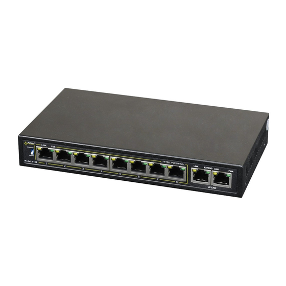
Switch 10 ports 10/100Mb/s
8 PoE ports 10/100Mb/s (data transfer and power supply)
2 ports 10/100Mb/s (UpLink)
Long Range mode (up to 250m)
30 W for each PoE port, supports devices complaint with
the IEEE802.3af/at (PoE+) standard
Supports auto-learning and auto-aging of MAC addresses
(1K size)
1. Technical description
1.1. General description.
The S108-C is a complete kit to build the CCTV system based on IP cameras. The switch and power supply unit are
housed in a metal enclosure.
Automatic detection of any devices powered in the PoE/PoE+ standard is enabled at the 1 – 8 ports of the switch. The
UP LINK ports is used for connection of another network device via RJ45 connector. The LEDs at the front panel indicate the
operation status (description in the table below).
The PoE technology ensures a network connection and reduces installation costs by eliminating the need to supply
a separate power cable for each device. This method allows supplying other network devices, such as IP phone, wireless
access point or router.
S108-C
v1.2
S108-C 10-port switch for 8 IP cameras
in the enclosure
Edition: 3 from 25.09.2019
Supercedes the edition: 2 from 14.02.2019
Features
:
LED indication
Metal enclosure – color white RAL 9003
warranty – 2 year from the production date
Example of use .
1
PL
EN**
Advertisement

Related Manuals for Pulsar S108-C


Summary of Contents for Pulsar S108-C
- Page 1 1. Technical description 1.1. General description. The S108-C is a complete kit to build the CCTV system based on IP cameras. The switch and power supply unit are housed in a metal enclosure. Automatic detection of any devices powered in the PoE/PoE+ standard is enabled at the 1 – 8 ports of the switch. The UP LINK ports is used for connection of another network device via RJ45 connector.
- Page 2 1.2 Block diagram. Fig. 1. Block diagram. 1.3 Description of components and connectors. Table 1. (See Fig. 2) Component No. Description (Fig. 2) Switch Switch mode buffer power supply unit (PS-1504830) 52 V DC/150 W Potentiometer adjusting the output voltage of the power supply (48÷53 V) LED light –...
- Page 3 Table 2. ( See Fig . 3) Component No Description (Fig. 3) 8 x PoE ports (1÷8) 2 x UPLINK port 52 V DC power supply socket Additional assembly elements Switch of mode Long Range Fig. 3. The view of the switch. Table 3).
- Page 4 Gross/Net weight 3,1/3,3 kg Protection class II (second) EN 60950-1:2007 -20°C ÷ 60°C Storage temperature Declarations * The given value of 30 W per port is the maximum value. The total power consumption should not exceed 120 W. 2. Installation 2.1.
- Page 5 Connection schemes 3. Optical indication. OPTICAL INDICATION OF THE SWITCH's POWER SUPPLY (1÷8) GREEN LED LIGHT (PoE) OFF- no power supply at the RJ45 port (the device is not connected or not compliant Indication of the PoE power with the IEEE802.3af standard) ON –...
-
Page 6: Weee Label
Waste electrical and electronic equipment must not be disposed of with normal household waste. According to the European Union WEEE Directive, waste electrical and electronic equipment should be disposed of separately from normal household waste Pulsar sp. j. Siedlec 150, 32-744 Łapczyca, Poland Tel. (+48) 14-610-19-40, Fax. (+48) 14-610-19-50 e-mail: biuro@pulsar.pl,...
Need help?
Do you have a question about the S108-C and is the answer not in the manual?
Questions and answers